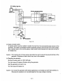
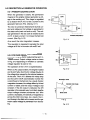
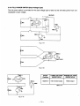
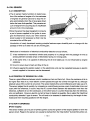
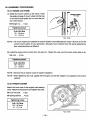
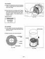
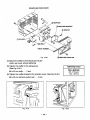
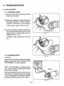
1
SERVICE
MANUAL
Model
RGV7500
PlJB-GS1436
Rev. 05/00
Section
Title
Page
l.'SPECIFICATIONS.......................................................................................................
1
2 PERFOMANCE CURVES...........................................................................................
2
3. FEATURES ..................................................................................................................
3
.
3-1 A.V.R. ALTERNATOR .............................................................................................
3-2 OIL SENSOR
........................................................................................................
.............................................................................................
3-4 NO RADIO NOISE ................................................................................................
3-5 LARGE FUELTANK ..............................................................................................
3-6 RUGGED TUBULAR FRAME ...............................................................................
3-7COMPACT AND LIGHT WEIGHT.........................................................................
3-8 MINIMAL MAINTENANCE ....................................................................................
3-9 LONG-LIFE DURABILITY .....................................................................................
3-3 QUIET OPERATION
3
3
3
3
3
3
3
3
4
5
4. GENERAL DESCRIPTION..........................................................................................
4-1 EXTERNAL VIEW .................................................................................................
5
4-2 CONTROL PANEL ................................................................................................ 6
4-3 LOCATION of SERIAL NUMBER and SPECIFICATION NUMBER ......................6
5 CONSTRUCTION AND FUNCTION
7
5-1CONSTRUCTION .................................................................................................. 7
5-2 FUNCTION ............................................................................................................
7
5-3 GENERATOR OPERATION ................................................................................
13
5-4 OIL SENSOR ...................................................................................................... 16
6 SAFETY PRECAUTIONS .........................................................................................
19
7 RANGE OF APPLICATIONS
20
8 MEASURING PROCEDURES
23
8-1 MEASURING INSTRUMENTS...........................................................................
23
8-2 AC OUTPUT MEASURING.................................................................................
26
8-3DC OUTPUT MEASURING................................................................................. 26
8-4 MEASURING INSULATION RESISTANCE ........................................................
27
9 CHECKMG FUNCTIONAL MEMBERS
29
9-1 V O L f M t r E R ....................................................................................................... 29
9-2AC RECEPTACLES ............................................................................................
29
29
9-3 No-FUSE BREAKER ...........................................................................................
.
...........................................................................
.
.
.
....................................................................................
..................................................................................
.
....................................................................
Title
. Page
9-4STATOR .............................................................................................................. 30
Sectior!
...........................................................................................
30
9-6 BRUSH................................................................................................................
31
9-7 A.V.R. (AUTOMATIC VOLTAGE REGULATOR)..................................................
31
9-8 IDLE CONTROL UNIT ........................................................................................
9-9 DIODE RECTIFIER.............................................................................................
33
9-10 OIL SENSOR ....................................................................................................
35
9-11 EXCITING COIL ................................................................................................
35
9-5 ROTOR ASSEMBLY
1O.DISASSEMBLY AND ASSEMBLY
34
...........................................................................
10-1PREPARATION and PRECAUTIONS ................................................................
10-2 DISASSEMBLY PROCEDURES .......................................................................
36
.
36
37
10-3ASSEMBLY PROCEDURES ............................................................................
45
10-4 CHECKING, DISASSEMBLY and REASSEMBLY ofthe FRONT PANEL ........50
11.TROUBLESHOOTING ............................................................................................
11-1 NO AC OUTPUT ................................................................................................
11-2 AC VOLTAGE IS TOO HIGH OR TOO LOW .....................................................
11-3 AC VOLTAGE IS NORMAL AT NO.LOAD.
BUT THE LOAD CANNOTBE APPLIED .....................................
11-4 NO DC OUTPUT................................................................................................
11-5 IDLE CONTROL(OPTI0NAL EQUIPMENT) .....................................................
12 WIRING DIAGRAM .................................................................................................
.
52
52
53
\
I
54
55
56
59
NOTE :As forthe servicing information
on engine protion. pleasereferto theEH41 engine
sewice manual.
1. SPECIFICATIONS
j:
Model
RGV7500
Brush, Self Exciting, 2-Pole, Single Phase
60 Hz
~~
~
~
~
Maximum Output
7300 W
Rated Output
6000 W
U
Voltage
Rated
Current
Power Factor
DC Output
Regulator
Voltage
120V1240V
I
V-8.3
12
A (100 W)
I
I Type
AVR
I
I Air-Cooled 4-Cycle, Overhead Valve Gasoline EngineI
1.o
EH41D
Model
in.)
(24.63
cu.
cm3
404
Displacement
9.5
Rated Output
I
hours
7.0 Approx.
Dry Weight
I
I
I
I
0.32 U S . gal. (1.2 liters)
Oil Capacrty
Dimensions (L x Wx H)
I
7.26 U.S. gal. (27.5 liters)
Fuel Tank Capacity
Starting System
HP I 3600 rpm
Automobile Gasoline
Fuel
Rated Coutinuous Operation
50N25A
I
Recoil
Starter
and
Optional
Electric
Starter
27.2 x 20.9 x 20.9 in. (690 x 530 x 530 mm)
198.4 Ibs. (209.4 Ibs.)' 190 kg (95 kg)*
* Electric starter motor is availableasoption.
-
1-
I
2. PERFOMANCE CURVES
RGV7500 / 60 Hz (6.0kVN240V)
Load
Rated
DC OUTPUT
DC Voltage................. 12 V
DC Ampere ................ 8.3A
DC output................... 100 W
The voltage curve shownin the left indicates the characteristicof DC output when charging a battery.
The voltage may be decreasedby 20% when the resistanceload is applied.
NOTE :It is possible to use both
DC and AC outputs simultaneously up to the rated output
in total.
- 2-
f
\
3. FEATURES
3-1 AVR ALTERNATOR
Output votage becomes more stable due
to AVR system.
3-2 OIL SENSOR
Oil sensor automatically shutsoff the engine whenever theoil level fallsdown below the lowerlimit to
protect the engine from seizure.
3-3 QUIET OPERATION
Robin RGV series generator delivers a quiet operation with
:
A quiet 4-stroke Robin Rro
OHV engine.
Extra large muffler and large air cleaner provide remakable quiet operation.
3-4 NO RADIO NOISE
Noise suppressor spark plugis equipped standardto prevent radio frequency interference.
3-5 LARGE FUELTANK
The large fuel tank
(27.5 L) allows more than7 hours of continuous operation which is sufficient for a half
day or one day
work without refueling.
3-6 RUGGED TUBULAR FRAME
Full cradle type rugged tubuler frame protects the generator all around.
".
3-7 COMPACT AND LIGHT WEIGHT
Newly developed brushless alternator enabled the RGV generators to be very compact
in size and light
in weight.
3-8 MINIMAL MAINTENANCE
A drip-proof alternator design.
No-fuse circuit breakers.
An electronic pointless ignition system.
-
3-
3-9LONG-LIFE DURABILITY
The heavy-duty 4 stroke Robin OHV engine :
Full rubber mount in a sturdy tubular frame.
* A forged steel crankshaft supported by two main ball bearings.
A pointless electronic ignition system.
* A cast-iron cylinder liner.
*
I
\
- 4-
4. GENERAL DESCRIPTION
4-1 EXTERNAL VIEW
FUEL GAUGE
CONTROL
PANEL
AIR CLEANER
RECOIL STARTER
IL GAUGE (OIL FILLER)
SENSOR
OIL
DRAIN
PLUG
OIL
FUEL TANK
CHOKE LEVER
SPARK PLUG
CAP
OUTLET
- 5-
4-2 CONTROL PANEL
HOUR
VOLTMETER
METER
:\.ET3iSTARTER
\
IDEL
TYPE) : ; F E Y
I
\
’
BREAKER
SWITCH
\
PILOT LAMP
A
K
C
L
E
I
I
NO-FUSE
DC OUTPUT
TERMINAL
DC CIRCUIT BREAKER
SWITCH
ENGINE
(RECOIL STARTER TYPE)
4-3 LOCATION of SERIAL NUMBER and SPECIFICATION NUMBER
Serial number and specification number are stamped onthe LABEL (MODEL NAME) stuck on the side
wall of rear cover.
I
NOTE :Always specify these numbers when inquiring about the generator or ordering spare
parts in
order to get correct parts and accurate service.
LABEL, MODEL NAME
-
6-
5. CONSTRUCTION AND FUNCTION
5-1 CONSTRUCTION
STATOR. COMPLETE
COVER
TROUGH
FRONTBOLT
EARING
BALL
RUBBER
MOUNT
Fig. 5 1
5-2 FUNCTION
5-2-1 STATOR
The stator consists of a laminated silicon steel
sheet core, a main coil and a condenser coil which
are wound in the core slots.
The condensercoil excites the rotor field coil which
generates AC voltage in the main coil.
3
Fig. 5-2
-
7-
5-2-2 ROTOR
The rotor consistsof a laminated siliconsteel sheet
core and a field coil which is wound overthe core.
DC current in the field coil magnetizes the steel
sheet core. Two permanent magnets are provided
for the primary exciting action.
Slip rings are provided on the rotor shaft to receive DC exciting current from A.V.R..
Fig. 5-3
5-2-3 BRUSW BRUSH HOLDER
An exciting current is supplied from the A.V.R to
the rotor. The brushes are made of carbon and
the brush-holder of plastic.
It is necessary to keep the contact pressure between the brushes and slip rings withing specific
limits. Thus, care must be taken of brush length.
Fig. 5-4
5-2-4 A.V.R. (AUTOMATIC VOLTAGE REGULATOR)
The automatic voltage regulator employs an elec-
tronic circuit to automatically regulate voltage.
~
Fig. 5-5
- a-
5-2-5 IDLE CONTROL UNIT
The idle control unit releases throttle valve when
the applied load current exceeds
0'.04A.
The two output wires from the main coils must go
through theZCT in the same direction.
NOTE :
It is normal that the engine speed goes
up for a
moment when you turn the key switch
to "STOP"
while the Auto Idle Switchis in "ON" position.
I
Fig. 5-6
5-2-6 NO-FUSE BREAKER
The no-fuse breaker protects the generatorfrom getting damageby overloading or short circuitin the
appliance. Table5-1 shows the capacity of no-fuse breaker
by each spec. and their object of protection.
I
SPECIFICATION
NO-FUSE BREAKER
60 HZ-120 V/ 240V
25 A (2-Pole, 2-Element)
OBJECT of PROTECTION
'
Total output amperage
Table. 5-1
5-2-7 DC CIRCUIT BREAKER
The 10 ampere DC circuit breaker mounted on
the control panel protects wholeDC circuit from
getting damage by overload or short circuit.
Fig. 5-7
- 9-
Table. 5-2
1
Caution :
The duplex 120V receptacle is protected by a
GFCl (Ground Fault CircuitInterrupter).
GFCl shuts off the output current from the
duplex 120V receptacle when a ground fault
occurs in the generator or the appliance.
Please note thatother receptacles arenot protected by GFCI.
\
TWIST
1
Caution :To connect theappliance to locking
receptacle, insert theplug into the receptacle and turn it clockwise to lock.
-
10-
5-2-9 GFCI RECEPTACLE
After starting the engine, check
the GFCI for'proper functioning by the following test procedure.
Push blue TEST button, The red
RESET button will pop out exposing the word TRIP. Power
is now off at
the outlets protected by the GFCI, indicating that the device is functioning properly.
If TRIP dose not appear when testing,
do not use the generator. Call a qualified electrician.
To restore power, pushRESET button.
WARNING :
If the RESET button pops out duringoperation, stop thegenerator immediately and call a
qualified electrician for checking
generator andthe appliances.
5-2-10 CONNECTING TO DOMESTIC CIRCUITS(HOUSE WIRING)
Fig. 5-9
WARNING :
.
This generator is a neutral grounded type.
ff a generator is to be connected to residential or commercial
power lines, such asa stand-by
power source during power outage, all connections must be made by a licensed electrician.
Faitwe in connection may result indeath, personal injury, damageto generator, damageto appliances, damage to the building's wiringor fire.
(a) When contnecting a Robin generatorto a house wiring, generator output power must
be taken from
the 240V-4P receptacle.
- 11 -
Utility high line
House circuitbreaker
-
I
v
I
I
I
I
120v
-
I
,A"
appliance
240V
120v
appliance
I
appliance
I
I
"
"
"
"
"
"
"
"
"
"
"
"
"
"
"
"
"
= 4P-Receptacle
Fjg. 5-70
(b) Install
Ii
A transfer switch must be installed to transfer the load from the commercial power sourceto the
1
generator. This switchis necessary to prevent accidentscaused by the recovery from power outage. '
Use a transfer switch of the correct capacity. Install transfer switch between the meter and the
AC breaker box.
Caution : If the neutral wireof house wiring is grounded,be sure to ground the ground terminal
of the
generator. Otherwise an electric shock may occurthe
to operator.
(c) Operating the generator.
Set the full power switch 120W
to 240V side.
Turn the house AC breaker
off before starting the generator.
it up.
Start the generator and warm
Turn the houseAC breaker on.
with electrical appliance(s) connected and with their switches on.
Caution : Do not start the generator
at starting.
Otherwise the appliance(s) may be damaged by the surge voltage
i
-
12 -
5 3 DESCRIPTION Of GENERATOR OPERATION
5-3-1 PRIMARY EXCITING ACTION
When the generator is started, the permanent
magnet on the engine rotates to generator a voltage in the exciting coil. This voltage is regulated FC
by a diode in the A.V.R. to feed a current to the
generator field coil. (FC). (See Fig.
5-11)
n
The rotoris turned an electromagnet by that current and rotatesso that voltage are generated in
the stator coils (main coil and sub coil). The voltage generated in the sub coils
is operatedby the
A.V.R. to feed a current to increase the field coil
current. (See Fig. 5-12)
EC
L""""""-J
ENGINE MAGNETO
Fig. 5-11
As a result, the rotor magnetism increases.
This operation is repeated to generate the rated
voltage at60 Hz in the main coil andDC coil.
5-3-2 VOLTAGE REGULATING MECHANISM
Connect a load
to the AC output terminal and increase current. Output voltage varies as shown
in Fig. 5-13 depending on whether an automatic
voltage regulatoris used or not.
The operationof the A.V.R. is explained below.
When an AC output is taken, the engine
is loaded
and its rpm falls, Also the AC voltage fails due to
the voltage drop caused by the internal resistance
of the coils. TheA.V.R. detects this voltage drop
and its built-in SCR automatically increase the
current flowsto the field coil.
As a result, the rotor
magnetism increase, the voltage fallen
by the load
current is raised: and the output voltage
is kept
constant. If the AC output is reduced, the SCR
operates in the opposite way to similarly keep the
output voltage constant.co,ndenser coil. When
current a increases, the density of magnetic flux
across the rotor core rises.
As a result, the current flowingin the fieldcoil increases and the generator output voltage is prevented from decreasing.
-
13-
i
Fig. 5-12
WITHOUT AVR
RATED VOLTAGE
v
I
4
A
Fig. 5-13
5-3-3FULL POWER SWITCH (Dual Voltage Type)
The full power switch is provided for the dual voltage type to take out the full rated power from one
receptacle in each voltage.
r--- 1
120/240v
MC1
240v
--
1
t.Fig. 5-14
MC1
MC2
1
Fig. 5- 15
-
r
1REC.~
Switch
Position
LOWER VOLTAGE HIGHER VOLTAGE
RECEPTACLE RECE
MC1
1
120/240 V
RECB
Half of rated output
Table. 5-3
-MC2
Fig. 5-16
-
14-
Rated output
I
I
Two main coils are wound over stator core. Each maincoil outputs half the rated power at the lower
voltage (120V). These main coils are wound
to be in the same phase. Thefull power switch reconnects
these main coilsin parallel or in series.
Fig. 5-14 shows acircuit diagram. When thefull power switchis set for single lower voltage indication
(120V), the switch positionis as indicated by the lower solid line
in the diagram. Fig. 5-15 is a simplified
representation of this circuit, showing thetwo main coils connected in parallel.
In this case, the higher
voltage (240V) at Rec. 3 cannot be taken out.Rec. 2 for the lower voltage can outputup to the rated
power (upto 30A if the rated currentis over 30A), and Rec. 1 can output up
to a totalof 15A.
When the full power switch is set for double voltage indication (120V/240V), the switch position
is as
indicated by theupper dotted line in Fig. 5-14. Fig. 5-16 is a simplified representationof this circuit,
showing the two main coils connectedin series. In this case, power can be taken simultaneously from
the receptacles for the both voltages. Rec.
3 for the higher voltage can outputtoup
the rated power, but
Rec. 1 and Rec. 2 for the lower voltage can output only up
to half the rated power each.
'
fullby
power switchin
Table 5-4is a summaryof the above explanation. Select.the proper output voltage
accordance with the appliance to be used.
-
15-
5-4 OIL SENSOR
5 4 1 DESCRIPTION
The oil sensor mainly functionsto detect position of the surface of engine oil in the crankcase
of engines for general use and to stop the engine automaticallywhen the oil level goesdown
below the lower limit specified.This prevents seizure of engine from occurringdue to insufficient
amount of oil in the crankcase.
OIL SENSOR
Since the sensor has been designed to.consume
a part of power supplied to the igniterto energize its electronics circuit, any other external
power supply is not necessary so that it can be
Fig. 5- 17
mounted at the oil filler port.
Introduction of newly developed sensing principle features super durability and no change with the
passage of time as it does not use any moving part.
Merits due to introduction of electrical conductivity detection are as follows ;
@ It has resistance to mechanical shocks and property of no change with the passage of time as
sensing element consists simply of electrodes having no moving parts.
@ At the same time, it is capable of detecting the oil level stably as it is not influenced by engine
vibrations.
@ No error occurs due to foam and
flow of the oil.
@
Influence
I
against the ignition system or the electronics units c a n be neglected because an electric
current supplied to the sensor can be decreased.
5-4-2 PRINCIPLE OF SENSING OIL LEVEL
There is a great difference between electric resistanceof air and that of oil. Since the resistanceof air is
far higher than thatof oil, more electric current passes through the oil than through the air, although
absolute valueof the currentis very small. The sensor detects this current difference andmake use of it.
The sensor judges the oil quantity,by comparing a current flowingacross apair of electrodes (innerand
outer) with the reference, in such a way that if a current flows between the electrodesmore than the
reference, sufficient oilis in the crankcase, on the other hand, if a current flows less than the reference,
oil is not sufficient. Since an electric current is flown to detect oil quantity, this is called the “electrical
conductivity detection” typeof sensor. The oil level to be detected is determined by the length of electrodes and their mounting positions with the engine.
5-4-3HOW IT OPERATES
[Power supply]
The sensor makes useof a part of primary power sourcefor ignition of the engine (igniter) to drive the
sensor circuit. Power tothe sensor can usually be derived from the “stop button”by branching wires out.
-
16-
[Judgement of oil level]
When sufficient oilis in the crankcase, both of inner and outer electrodes are immersed
in the oil through
which current flows across the electrodes. The sensor judgesoilthat
in the crankcase is sufficient. When
oil level goes down and the inner electrode is exposed to the air due to consumption of oil, no c
between the electrodes as airis considered to be electrically nonconductive. The sensor
in this case
judges that oil is insufficient.
[Decisionof oil shortage]
.Oil level at the electrodes may go down momentarily probably due to the engine being slanted or
by vibration even
if a sufficientoil is in the crankcase. For that reason, the sensor has an electronic time
circuit to preventit from interpreting as short
of oil when amount ofoil is sufficient. The sensor has been
designed so that the engine is to be stopped only when oil-shortage is detected
5 seconds
for
uninterrupted. The timer employs an integration circuit itand
is tobe reset when the inner electrode
is soaked in
the oil again before the sensor decides
it as oil-shortage. The oil level where the sensor decides oilas
shortage, when oil levelgoes down gradually,is called "threshold level".
[Automatic stop of engine]
When the sensor decides as oil-shortage,it makes the engine to stop running automatically for protection of engine. Oncethe stopping circuit is activated,
it keeps functioning until
it confirms that the engine
has made a complete stop, then the circuit stops functioning automatically.
5-4-4 BLOCK DIAGRAM OF THE CIRCUIT
Power circuit
Innerpole
oil
1
-
Detection
circuit
-
Deley circuit
igniter
Stopping
circuit
'
+
-Pole
Engine
Fig. 5-18
0 Power circuit ..........This
rectifies a part of power to the igniter and regulates
it to supply thest&+
lized powerto necessary circuits.
- 17-
@ Detection circuit..... This detects quantity ofoil, sufficient or not, accordingto difference of electric
resistance across inner and outer electrodes.
@ Delay circuit...........This his prevents the sensor from making an unnecessary stop of the engin
by momentary lowering of theoil level due to the engine being slanted or
affected by vibrationin spite of sufficient oilin the crankcase.
@
Stopping
I
circuit...... This automatically stops the engine running.
5-4-5 CAUTIONS TO BE TAKEN ON HANDLING THE SENSOR
(1) Oil sensor unit
0 Be sure not to damage each
wire. Broken or short-circuited power supply wires and/or a ground
ing wirein particular may leadto malfunction or breakdown.
@ The sensor is not interchangeable from engine to engine because the sensor is to be exclus
installed individually in each engine employed.
(2) Mounting and wiring of oil sensor unit
0 Although this has been designed to have enough antinoise properties
in practical use, do not
route the sensor wiringsin the vicinity of noise-generating sources such
as ignition plugsor high
voltage cords. This may cause malfunction or breakdown.
I
\
@ Since capacity of power sourceis limited, current flown in the electronic circuit
of the sensor is
kept as low as possible. Be sure
to use terminals with
a high contact reliability of more than o
that
f
tinned terminals.
(3) Operation of oil sensor
@ If operating with the engine kept tilted, oil surface inside of the engine varies and the correct
oil
~
level can not to be detected whichin turn obstructs the preventing functionof engine seizure.
Operate the engine by keeping
it level.
I
@ When starting the engine with an insufficient oil in the crankcase, engine starts onceitthen
stops
I
after
automatically
for
it runs
i
5 seconds.
@ When the engine has been stoppedby the oil sensor, voltage remained in the electronic circuit
prevents the sensor from being restarted for3 seconds after the engine stop. Tryto restart the
engine after3 seconds or more.
-
j
18-
i
~
6. SAFETY PRECAUTIONS
1. Use extremecaution near fuel. A constant danger of explosion or fire
exists.
Do not fillthe fuel tank while the engine
is running. Do not smoke or use open flame near the fuel tank.
Be careful notto spill fuelwhen refueling. If spilt, wipeit and let dry before starting the engine.
2. Do not place inflammablematerials near the generator.
Be careful notto put fuel, matches, gunpowder,
oily cloth, straw, and any other inflammables near the
generator.
3. Do not operate the generator in a room, cave or tunnel. Always operate in a well-ventilated
area.
-
Othetwise the enginemay overheat and also, the poisonous carbon monoxide containedin the exhaust gaseswill endanger human lives. Keep the generator at least
1 m (4 feet) awayfrom structures
or facilities duringuse.
4. Operate the generator on a level surface.
If the generatoris tilted or moved during use, there
is a dangerof fuel spillage and a chance that the
generator maytip over.
5. Do not operate with wet hands or in the rain.
Severe electric shock may occur.
If the generatoris wet by rain or snow, wipe it and thoroughly dry
it
before starting. Don’t pour water over the generator directly nor wash it with water. If the generator
is
wet with water,.the insulations will be adversely affected and may cause current leakage and electric
shock.
6. Do not connect thegenerator to thecommercial power lines.
or damage to the generator. Use a transfer switch (Optional parts) for
This may cause a short-circuit
connecting with indoor wiring.
NOTE :The parts numbersof the transferswitches and of the plastic box to store them
are as shown in
Table 6-1.
~
Name
Part
No.
Part
36545604-08 Switch
Transfer
1
Phase
Allowable
Q’ty
Current
1
1
15 A
367-45605-08
Transfer Switch
1
1
30 A
340-45606-08
Transfer Switch
1
1
60 A
367-43008-08
Plastic Box
1
1
30 A
34843009-08
I
I
Plastic Box
1
I
1
I
60 A
Table. 6-1
7. Be sure to check and remedy the cause of circuit.breaker tripping before resetting
it on.
CAUTION :ff the circuit breaker tripped off as a result of using
an electrical appliance, the cause
can be an overloador a short-circuit.In such acase, stop operation immediately and carefully
check the electrical appliance and AC plugs for faulty
wiring.
-
19 -
7. RANGE OF APPLICATIONS
Generally, the power rating of an electrical appliance indicates the
amount of work that can be done by it.
The electric power requiredfor operating an electrical applianceis not always equalto the output wattage of the appliance.The electrical appliancesgenerally have a label showing their rated voltage, frequency, and power consumption (input wattage). Thepower consumption of an electrical appliance is
the power necessary for using it. When using a generator for operating an electrical appliance, thepower
factor and starting wattage must be taken into consideration.
In order to determine the right size generator,it is necessary to add the total wattage of all appliances to
be connected to the unit.
Refer to the followings to calculate the powerconsumption of each applianceor equipment by its type.
(1) Incandescent lamp, heater, etc. with a power factor
of 1.0
Total power consumption must be equal to or less than the rated output of the generator.
Example :A rated 3000W generator canturn thirty 1OOW incandescent lampson.
(2) Fluorescent lamps, motor driven tools,
light electrical appliances, etc. with a smaller power
factor
Select a generator with a rated output equivalent to 1.2 to 2 times of the power consumption of the
load. Generally the starting wattage of motor driven tools and light electrical appliances are 1.2 to 3
times lager thantheir running wattage.
Example : A rated 250 W electric drill requires a 400 W generator to start it.
NOTEl :If a power factor correction capacitor not
is applied to the fluorescent lamp, the more power
shall be requiredto drive the lamps.
NOTE2 :Nominal wattage of the fluorscent lamp generally indicates the output wattage of the lamp
Therefore, if the fluorescent lamp has no special indication as to the power consumption,
ciency should be taken into account as explained in(5)
Item
on the following page.
(3) Mercury lamps with a smaller power factor
Loads for mercury lamps require2 to 3 times the indicated wattageduring start-up.
Example :A 400 W mercury lamp requires800 W to 1200 W power source to be turned on. A rated
3000 W generator can power two or three 400 W mercury lamps.
(4) Initially loaded motor driven appliances such as water pumps, compressors, etc.
These appliances require large starting wattage whichis 3 to 5 times of running wattage.
Example :A rated 900 W compressor requiresa 4500 W generator to drive it.
NOTEl :Motor-driven appliances require the aforementioned generator output only at the starting.
their motors are started, the appliances consume about
7.2 to 2 times their rated power consumption so that the excess power generated by the generator
can be used for other electrical
appliances.
NOTE2 :Motor-driven appliances mentioned in items
(3) and (4) vary in their required motor starting
it is difficun
to determine
the optimum
power dependingon the kind of motor and start-up load.
If
generator capacify, select
a generator with a larger capacity
- 20-
' *
8'
(5) Appliances without any indicationas to power consumption
Some appliances have no indication asto power consumption; but instead the work load (output)is
indicated. In such a .case, power consumption
is to be worked out accordingto the numerical formula
mentioned below.
(Output of electrical appliance)
= (Power consumpition)
(Efficiency)
:
Eff iciencies.of
some electrical appliances are as follows
Single-phase motor................................
0.6 t0 0.75
Fluorescent lamp ...................................
0.7 to 0.8
The smaller the motor, the
( lower the efficiedCY.
Example 1: A 40W fluorescent lamp means that its luminous output
is 40W. Its efficiency is0.7 and
accordingly, power consumption will be 40+ 0.7=57W. As explained in Item (2),multiply
this power consumption value of
57 W by 1.2 to 2 and you will get the figure of the necessary capacity of a generator. In other words, a generator with a rated output of O
1OOW
capacity can light nine to fourteen
40 W fluorescent lamps.
Example 2 :Generally speaking, a400 W motor means thatits work load is 400 W. Efficiency of this
motor is 0.7 and power consumptionwill be 400+0.7= 570 W. When this motoris used for
a motor-driven tool, the capacity
ofthe generator should be multiple 570
of W by 1.2to 3 as
explained in the Item(3).570 (W) x 1.2 to 3 = 684 (W) to 1710 (W)
I
I
Frequency
I
etc. heater, lamp,
lncandesent
60 Hz
6000 W
Fluorescent lamp, Motordriven tool,
general-potpose
approx. 3000 W
2000 W
Mercury lamp, etc. approx.
Pump, compressor, etc.
approx. 1400 W
Table. 7-1
- 21 -
I
NOTES :Wiring between generator and electrical appliances
1. Allowable current of cable
Use a cable with an allowable current that is higher than the rated input current of the load
appliance). If the input current is higher than the allowable current
of the cable used, the cable will
become excessively heated and deteriorate the insulation, possibly burning it out. Table
7-2 shows
cables and their allowable currents for your reference.
2. Cable length
If a long cable is used, a voltage drop occurs due to the increased resistance in the conductors
creasing the input voltage to the load (electtical product).
As the load can be damaged. Tabl
a result,
7-2shows voltage drops per100 meters of cable.
i
Resistance
Allowable
Sectional
wire e,ement
No’
ohm”00m
area / mm3 current / A
mm
0.75
7
1.25
12
23
5.5
35
3.5
per 100 m
1A
3A
SA
2.477
2.5 V
8V
12.5 V
, 5 0/ 0.18
1.486
1 . 5 ~
sv
37 I 0.26
17 0.952
1.OV
3V
5.0V
8V
1OV
45 I0.32
0.517
1.5 V
2.5 V
4V
5V
6.5 U
7.5 V
70 J 0.32
0.332
1V
2V
2.5V
3.5V
4V
5V
30 10.18
2.0
Voltage drop
15A
8A
1 5 ~ 1av 1 2 ~
15V
Table. 7-2
1
10
0x R x I x L
Voltage drop indicates as V=
R
means resistance ( SZ / 100 m) on the above table.
I
meanselectriccurrentthroughthewire
L
meansthelength of thewire(m).
(A).
The lengthof wire indicates round length,
it means twice the length from generator
to electricaltools.
-
22-
12
12V
(
8. MEASURING PROCEDURES
8-1 MEASURING INSTRUMENTS
8-1-1 "Dr. ROBIN" GENERATOR TESTER.
The "Dr. Robin" generator tester is exclusively
designed for fast, easy diagnosisand repair of
Robin generators. The "Dr. Robin" has the following features:
(1) Functions of voltmeter, frequency meter,
megger tester, capacitance meter and circuit
tester are combined in one unit.
(2)Fast and easy readout by digital indicator.
(3) Built-in automatic battery checker indicates the
time to change batteries.
Fig. 8-1
(4) Tester and accessories are installed in a handy,
sturdy case for easy carrying.
SPECIFICATIONS
Dr. Robin
MODEL
Part Number
I
388-47565-08
0 to 500 V AC
Voltage
I Frequency
I
to
~~
Measuring
Resistance
Range
Condenser Capacity
25
70 Hz
I
0.1 to 1.999 Q
10 to 100 p F
Insulation Resistance
3M Q
Circuit Protector
Fuse
I
Power
Source
I
Accessories
2 x 6F44P
(006P)
Dry
Battery
Cell
Test leads with needle probes. . . 1 set
Testleads with jack plugs . . . 1set
Dimensions (L x W x H)
I
I
285 mm x 200 rnm x 110 mm
1.6 kg
Weight
Table. 8-1
The "Dr. Robin" generator tester can be ordered from Robin generator distributors by the following part
number.
~
If you do nothave a "Dr. Robin" generator tester, use the instruments described in the following section
far checking generator parts.
- 23-
8-1-2 INSTRUMENTS
(1) VOLTMETER
AC voltmeter is necessary. The approximate
of the voltmeters be
to used
AC voltage ranges
for various typesof generators areas follows:
0 to 150V:Type with an output voltage
of 110
or 120V
0 to 300V:Type withan output voltage of 220,
230 or 240V
0 to 15OV,0 to 330V : Dual voltage type
FOR AC
Fig. 8-2
I
(2) AMMETER
AC ammeter is necessary. AnAC ammeter
with a range that can be changed according
to the current rating of a given generator is
most desirable. (About 10A, 20A, 100A)
FOR AC
Fig. 8-3
(3) FREQUENCY METER
Frequency range:About 45 to 65Hz
NOTE :Be carefulof the frequency meter’s input
voltage range.
-
24-
1
(4) CIRCUIT TESTER
Used for measuring resistance, etc.
(5) MEGGER TESTER
Used.for measuring generator insulation resistance. Select one with testing voltage range
of 500V.
I
I
Fig. 8-6
(6) TACHOMETER
Use the contactless type tacho meter.
1
f
Fig. 8-7
- 25-
8-2 AC OUTPUT MEASURING
TO AC RECEPTACLE
v
Fig. 8-8
Use a circuit like the shown in Fig.8-8 for measuring AC output. A hot plate or lampwith a power factorof
1.O may be used as a load. Adjust the load and rpm. and check that the voltage range is as specified in
Table 8-2at the rated amperageand rated rpm.
I
Rated voltage
Voltage range
I
120 v
112 -128 V
I
240 W
-
224 256 V
Table. 8-2
8-3
DC OUTPUT
I
MEASURING
1
To DC Terminal
9
T
I
i. .i
Fig. 8-9
Measurement of DC output is executed with the switch turnedON while the currentis regulated at 8.3A
by adjusting the load tothe generator. If the voltage is within the range from6V to 14V, the voltage output
is normal.
NOTE :If a batteryis connected as a loadto the generator,the DC output voltage will increase by
approximately 1 to 2 V: Therefore, carefully observe the electrolyte level
and do not overcharge
I
the 6attev.
\
-
26-
8-4 MEASURING INSULATION RESISTANCE
Use a "Dr. Robin"generator tester in megger tester
mode or use a megger tester to check
the insulation resistance. Remove the control panel, and
disconnect the connector of GREEN lead for
ground. Connect a megger tester to one of receptacle output terminals and the ground terminal, then' measure the insulation resistance.
An
insulation resistanceof 1 megohm or moreis normal. (The original insulation resistance at the time
of shipment from the factory is 10 megohm or
more.) If it is less than 1 megohm, disassemble
the generator and measure the insulation resistance of the stator, rotor and control panelindividually.
Fig. 8-10
NOTE :Turn on the no-fuse breaker beforemeasurement.
STATOR
Measure the insulation resistance between
BLUE lead and the core.
(2)Measure the insulation resistance between
WHITE lead and the core.
(3) Measure the insulation resistance between
BROWN lead and the core.
(1)
I
Fig. 8- 11
ROTOR
Measure the insulation across onethe
ofsoldered
terminals of the rotor andthe core.
Fig. 8-12
-
27-
CONTROL PANEL
Measure the insulation resistances between the
live parts and the grounded parts.
Fig. 8- 13
Any part where the insulation resistance
is less than 1M Q has faulty insulation, and may cause electric
leakage and electric shock.
Replace the faulty part.
- 28-
’
...^ :.. .
9. CHECKING FUNCTIONAL MEMBERS
9-1 VOLTMETER
Check the voltmeterif it is turned on by applying
specific voltage. Voltmeter cannot be checked with
circuit tester because its resistance
is too large.
0 Check that no disconnection nor short-circuit
occurs with a tester, and the internal resistance
is aroundOOk ohms normally.
@ Turn on the commercial power supply input
and check the indication.
VOLTMETER
Fig. 9-7
9-2 AC RECEPTACLES
Using a “Dr. Robin” or a circuit tester, check continuity between the two terminals at the rear of
the AC receptacles while the receptacle is
mounted on the control panel. When continuity is
found between theoutput terminals of the receptacle with a wire connected across these terminals, the AC receptacle is normal. When the wire
is removed and no continuity is found between
these terminals, the receptacles are also normal.
Fig. 9-2
9-3 NO-FUSE BREAKER
I
Check continuity between each of two terminals
at the rear of the no-fuse breaker while it is
mounted on the control panel. Normally, thereis
continuity between each of the
two when the nofuse breaker is on while there is no continuity when
the no-fuse breakeris off.
Fig. 9-3
- 29-
9-4 STATOR
Disengage connectors on the wires from stator
and check the resistance between wires with a
“Dr.Robin” or a circuit tester referring to the
fol-.
lowing table.
Fig. 44
r
Stator coil
DC coil
Hz-Voltage
60-1 20/ 240
Red-White
Black-Blue
0.16 SZ
0.16 SZ
BrownBrown
WhiteLight green
0.11
D
0.61 SZ
NOTE :If the circuit tester is not sufficiently accurate, it may not show the values given and may
erroneous readings. Erroneous readings will also occur when there
is a wide variationof resistance amongmil windings or when measurementis performed at ambient temperaturesdifferent from20 OC (68 O F ) .
9-5 ROTOR ASSEMBLY
I)
Field coil
Removethe brush holderand measure resistance
between the slip rings.
Resistance
NOTE :If the circuit tester is not sMicientIy accurate, it may not show the valuesgiven andmay
give erroneous readings.
Erroneous reading will also occur when there
is a
wide variationof resistance among coil windings
or when measurement is performed
at ambient
temperatures different from from
20 ’C (68’F).
-
30-
-
‘SUP UNG
Fig. 9-5
2) Cleaning Slip rings
The slip ring surfaces must be uniformly bright.
Slip rings showing black spots, excessive
wear,
or uneven wear mustbe repaired.A stained slip
ring lowers generator efficiency and output voltage. Polish the slip rings with fine sandpaper while
turning the rotor until rough spots disappear. Care
should be taken notto touch the rotor coils with
the sandpaper.
Fj3. 9-6
9-6 BRUSH
The brushes mustbe smooth where they contact
the slip rings. If not, polish smooth the brushes
with sandpaper. A brush that is not smooth produces arcs betweenthe brush and slip ring leading to possible damage. Usable brush lengths are
from 5 mm to 15 mm (0.2 " to 0.6").
A brush shorter than5 mm must be replaced because decreased contact pressure between the
brush and slip ring lowers generator efficiency and
output voltage.
Fig. 9-7
9-7 A.V.R (AUTOMATIC VOLTAGE REGULATOR)
1) Features
This AVR operates to control the field current
in
order to maintain the output voltage for the
AC
current, which generated by the magnetic flux by
the fieldcoil.
2) A.V.R. trouble maybe identified by simply looking at theA.V.R., or by the inter-lead resistance
with a'tester, or actually mounting it in the generator and operatingit.
of the A.V.R.
1
- 3.1-
Fig. 9-8
..
(a) A.V.R. TROUBLE IDENTIFICATION by APPEARANCE
If an A.V.R. electronic part is burnt dark, or the surface epoxy resin melted,
it often indicates A.V.R.
trouble.
(b) IDENTIFYING A.V.R. TROUBLE by CHECKING INTER-LEAD RESISTANCE
Check the inter-lead resistance of the
A.V.R. with a tester, referring to the following table.
If the tester readings very greatly from the values specified
in the tableon'next page, theA.V.R. is
faulty.
NOTE :lake teater inaccuracy into account
in reading the tester.
(c) IDENTIFYING A.V.R. TROUBLE by MOUNTING and OPERATINGTHE
in GENERATOR
SCR or transistor damage cannot be detected by simply looking at the A.V.R. or checkinglead
the
resistance. Check it by mounting the suspectedly faultyA.V.R. in a normal generator, or mount a
mormal A.V.R. in a generator which fails to generate voltage.
Checking table for analogue circuit tester.
~~
~~
Apply black (minus) needleof the circuit tester
Analogue circuit tester
Yellow
Yellow
Apply red ( P W
needle of the
circuit tester
-
Brown or
Yellow
Red
White
Light
green
03
03
03
03
-
105 kQ
03
200 kSZ
03
100 kQ
Red
03
White
03
46 kQ
-
Light green
7.5 k 0
250 kS2
130 kS2
Brown or Yellow
03
200 kS2
100 kSZ
03
6 kQ
L
Table. 9-2
\
- 32-
9-8 IDLE CONTROL UNIT
Check the resistance between five terminalsof
IDLE CONTROLUNIT with circuit tester.
L'
Terminal numberof
the IDEL CONTROL UNIT
Fig. 9-8A
Terminal numberof the IDLE CONTROL UNIT
Apply blacCk 0needle of the circulit break
Sircuit tester (with battery
power source 1.5 V)
@
110kQ
0
Apply red 0
needle of the
circuit breaker
0
0
0
0
0
@
Fig. 9-8B
I
03
lo Is
,110kSZ 50 kQ
110 kQ
110 ksl
03
03
03
110 kQ
110 kQ
50 kQ
03
03
03
03
03
03
50 kQ
110 kQ
85 kQ
85kQ
I
F,
50 k Q
80 k Q
03
80 kQ
tt?rrneasu
OQ
I
ng range 1000 kS2
Table. !
NOTE :The resistance readings vary depending on the @pes
of circuit testers.
The above table shows an example
of the resistance readings measured an
by ordinary analogue circuit tester
with 1.5 volt battery power source:
It is advisable foryou to check the resistance readings using your standard circuit tester an
revise the checking table.
- 33-
9-9 DIODE RECTIFIER
DIODE RECTIFIER
Brown
Orange
Brown
CIRCUIT TESTER
Fig. 9-10
Fig. 9-11
Circuit insideof the diode rectifiersis as shownin Fig. 9-10. Check continuity between each terminal by
using a circuit tester as shown
in Fig. 9-11. The rectifieris normal when condtinuity is as follows:
* Checkina table for analoaue circuit tester.
Apply black (minus) needle of the circuittester
Analogue circuit tester
Apply red (plus)needle of
the circuittester
Brown
Brown
Orange
Brown I White
Brown
-
No continuity
No continuity
Continuity
Brown
No continuity
-
No continuity
Continuity
-
Continuity
Continuity
Orange
Brown I White
No continuity
Continuity
No continuity No continuity
-
.
Table. 9-4-7
Checkina table for diaital circuittester.
Apply red (plus)needle of the circuit tester
Digital circuit tester
I
Apply black(minus) needle
of the circuit tester
Brown
Brown
Orange
Brown I White
BlQWtl
-
No continuity
No continuity
Continuity
BmWn
No continuity
-
No continuity
Continu'@
Orange
Continuity
Continutty
-
Continuity
Brown I White
I
.
No continuity No continuity No continuity
Table. 942
- 34-
-
*
.
..
NOTE 1 :Because of the difference hieasdnng
of
method between the analogue circuit tester and the
digital circuit tester, polarity
of testemeedles should be reversed.
NOTE 2 :"Continuiv means forward direction characteristics of the diode, and different from short
circuit condition (in which
a pointer of the tester goes
out of its normal scale), shows resistance
to some extent. When results of the checking indicates failure even in one section, replace
with a new one.
NOTE 3 :Simpson brand analogue testers have the characteristics as same
as the digital circuit tester.
9-10 OIL SENSOR
(1) Disconnect two (2) wires comming from the
sensor at the connection.
(2) Loosen the sensor to removeit from the engine.
(3) Plug the opening of oil filler hole (created after
sensor is removed) with suitable means such
as oil gauge.
(4) Connect the removed wires again with the oil
sensor.
(5)Start the engine with the
oil sensor removed
Fig. 9-12
and confirmif ;
a. Engine stops after 5 seconds which is normal, or
b. Engine does not stop after more than
10 seconds which is unusual.
NOTE :The sensor will not operate properly when wire is broken or pooriy connected. Check the
for correct connection. Ifit fails to stop within5 seconds after the wirings have checked, the
sensor is wrong. Replace the sensor with new one.
9-11 Exciting coil
(1) Disconnect two (2)yellow wires which come out from the exciting coil through theofhole
the
AVR in the control box.
crankcase and connected with
(2) Check the resistance between these
two (2) yellow wires with a circuit tester.
Resistance
24Q
-
35-
IO. DISASSEMBLY AND ASSEMBLY
10-1 PREPARATION and PRECAUTIONS
'
1) Be sure to memorize the location of individual parts when disassembling the generator
so that the
generator can be reassembled correctly. Tag the disassembled part with the necessary informationto
facilitate easier and smoother reassembly.
2) For more convenience, divide the partsinto several groups and store them in boxes.
3) To prevent bolts and nuts from being misplaced or installed incorrectly, replace them temporarily
to
their original position.
4) Handle disassembled parts with care; clean them before reassembly using a neutral cleaning fluid.
5 ) Use all disassembly/assembly tools properly, and use the proper tool for each specific job.
- 36-
10-2 DISASSEMBLY PROCEDURES
~
Description
Step Part to remove
~
Tool
Screw driver (+)
(1) Take off the eight screws and
remove
Control box
1
~
Remarks
the control panel from the control box.
(See Fig. 10-1 .)
5 x 12 mm screw and
washer Ass'y (black) . . . 8 pcs.
(2)Disconnect the connectors on wiring
the
from the control box to the alternator.
(3)Take off the bushing from the back of
the control box. (See Fig. 10-2.)
Press the upper end
of
the bushing and pull
out.
Fig. 10-1
Fig. 10-2
I
(4) Take off
I
I 10rnrn box wrench
the flange fourb o l t s and
r
Fig. 10-3-2
Fig. 10-3-1
I
I
1
- 37-
I
Step Part to remove
%el Tank
2
Description
Remarks
(9) Discharge
fuel
from
the
tnak.
Use
utmost
care
about
hazard.
strainer.
fuel
fire
1.the
Shut
2. Remove the strainer cup.
3. Put a vessel to receive fuel under the Wipe
off split fuel
strainer
and
open
the
fuel cock to
thoroughly.
discharge fuel. (See Fig.10-4.)
4. Attach the strainer cup to the strainer
Do not lose the filter
body.
Tool
screen.
Fig. 10-4
?hers
(2) Disconnect rubber pipe from the strainer.
Loosen the hose clamp ontop
theof the
out the rubberpipe from
strainer and pull
the strainer.
~
~~~
~
12 mm spanner a
(3) Remove the rear plate.
DOX wrench
10 mm spanner a
3ox wrench
(4) Take off the four bolts and rubber (fuel
tank) and then remove the
fuel tank.
(See Fig. 10-6.)
I
I
V I
Fig. 10-6
Fig. 10-5
I
I
I
- 38-
I
Step Part to remove
T l M u f f l e r and
Muffler cover
Remarks
Description
Tool
12 mm spanner or
box wrench
(1) Remove the muffler cover from the
muffler.
6 x 10 mm bolt andwasher Ass'y . . . 4 pcs.
(See Fig. 10-7.)
~
10 mm spanner or
box wrench
(2) Remove the two bolts whichfix the
muffler to the rear cover. Loosen
the two
bolts on the muffler flange and remove
the muffler from the engine.
8 x 20 mm bolt and washerAss'y . . - 2pcs.
8 mm spring washer. . .2pcs.
Muffler gasket . . 1 pce.
.
Fig. 10-8
Fig. 10-7
I
-
39-
I
Description
Part to remove
'ipe Frame
Remarks
Tool
1) Removethe nuts which are fixing engine
and alternator to the mount rubbers.
(See Fig. 10-10.)
12 mm spanner
2) Using a chain-block, sling
up the engine Remove the air
and alternator and dismount from the cleaner cover for
dismounting.
frame.
I
MOUNT
(ALTER
MOUNT RUBBER
(ENGINE SIDE : Ppcs)
Fig. 10- 10
12 mm spanner or
socket wrench
3 ) Remove the mount rubbers from the
frame. Loosen the nuts on the bottom
side of the frame. (See
Fig. 10-11.)
d8 flange nut. . . 4 pcs.
n
Fig- 10-11
I
- 40-
itep Part to remove
5
Brush and
Rear cover
Description
Remarks
Tool
(1) Remove the brush holder.
(See Fig. 10-12.)
64screw.. .2
pcs,
(2) Remove the four bolts which fasten the
rear cover to the front cover.
(See Fig. 10-73.)
64bolt.. . 4 pcs.
10 mm spanner or
box wrench
I .
Fig. 10- 13
7. 10-12
(3) Removethe rear coverby hitting on theDo not give a strong
hit Plastic hammer
on theboss or legs.
legs of rear cover with a plastic hammer
to loosen.
Fig. 10-14
L
- 41 -
Step Part to remove
6
Stator
Remarks
Description
Tool
(1) Remove the stator cover.
STATOR COVER
E
Fig. 10-15
STATOR COVER
STATOR
-
\
WASHER :4 pcs.
SPR'NG
COVER BOLT :4 pcs.
Fig. 10-16
I
-
- 42-
I
~
Part to remove
3otor
7
Remarks
Description
I
Tool
Box wrench
Plastic hammer
(1) Take off the through bolt.
Apply a box wrench on the headof
through bolt. Hit the wrench handle with
a hammer counter-clockwise to loosen.
Fig. 10-17
~
~~
(2) Put the engine on the working table
recoil starter side down.
(3)Use a bolt and
oil as a toolfor pulling out
rotor in the following procedures:
1. Pour engineoil into the center hole
of
rotor shaft. Fill with oil tothe shaft end.
(See Fig. 10-18.)
2. Prepare abolt with the following thread
size : M12 x P 1.5
3. Apply a few
turns of seal tape around the
tip of the bolt. (See Fig.10-19.)
1
I
Fig. 10- 18
I
Fig. 10- 19
I
- 43-
I
Part to remove
3otor
Description
Remarks
4. Screw the boltinto the thread of the rotorDo not stickout your
face over the rotor.
shaft.
5. Torque the bolt using a socket wrenchIt may jump up on
until the rotor comes
separation.
off loose.
Tool
Socket wrench
The hydraulic pressure inside the
rotor shaft takes apart the rotor from
the engine shaft.
:4) Wipe off oil thoroughly from rotor shaft
and enaine PTOshaft.
3ont Cover
12 mm socket
wench
(1) Remove the front cover.
Loosen the fourbolts and remove the
front cover.
M8 x 20mm bolt and washer
Ass'y ... 4 pcs.
I
Fig. 1021
7
- 44-
10-3 ASSEMBLY PROCEDURES
-
10-3-1 ENGINE and FRAME
(1) Attach the mount rubbersto the frame. Insert
the setting tongue
of mount rubber into the hole
.on the frame and tighten the nut from the bottom of the frame.
FRAME UPPER
M8 flange nut . . . 4 pcs.
-
11.8 13.7 N-m
120 - 140 kg-cm
8.7 - 10.8 ft-lb
Fig. 10-22
NOTE :The mount rubbers
are selected to reduce vibration most effectively by model. Be sure to use
correct mount rubber for your generator. Although mount rubbers have the same appearance
their characteristicsare different.
(2) Install theengine into the frame from the
side of it. Tighten the nuts over the mount rubber bolts
to fix.
M8 nuts . . .2pcs.
120 - 140 kg-crn
8.7 10.8 ft-lb
-
NOTE :Remove the air cleaner cover for easier installation.
NOTE :When tightening the nuts, slightlylift the engineso that the weightis not applied to the mount
rubbers.
10-3-2 FRONT COVER
Attach the front cover to the engine main bearing
cover. Match the faucet joint and tighten the bolts.
M8 x 20 mm bolt. . - 4 pcs.
M8 springwasher. . . 4 pcs.
-
11.8 13.7 N-m
-
120 140 kg-cm
8.7 - 10.1 ft-lb
Fig. 10-23
- 45-
10-3-3 ROTOR
(1)Wipe off oil, grease and dust from the tapered
portion of engine shaft and matching tapered
hole of rotor shaft.
(2) Mount the rotor to the engine shaft. Tighten
the through bolt. Apply a wrench on the through
bolt and hit wrench handle clockwise with a
hammer to tighten. If an impact wrench is
available, use it.
Tightening torque :
Fig. 10-24
-
22.5 24.5 N-m
230 250 kg-cm
16.6 18.5 ft-lb
-
-
10-3-4 STATOR
(1) Put the stator in the rear cover settingthe four
grooves onthe side of stator with thread holes
of the rear cover.
(2) Attach the stator cover around the stator.
STAT0
Fig. 10-25a
Fig. TO-25b
-
46-
10-3-5 REAR COVER
(1) Put the rear cover with stator over the rotor.
Tap on the rear cover evenlywith a plastic
hammer to press the rotor bearing into the rear
cover.
(2) Fix the rear cover
to the adaptor with four bolts,
spring washers, and washers.
M6x160mmbolt ... 4pcs.
M6 spring washer. . . 4 pcs.
M6 washer . . . 4 pcs.
-
50 60 kgcm
3.6 4.3ft-lb
-
(3) Attach the bushing over the lead wire drawn
out from the rear cover. Press the smaller end
of the bushing into the window of the rear
cover.
(4)Attach the5 mm terminal of the grounding wires
(green / yellow) to the unpainted thread hole
of the frame base plate using a5 mm brass
screw.
Fig. 10-27
(5) Install the alternator assembly into the frame
Tighten the nuts over the mount rubberbolts
to fix.
M8 nuts. . .2pcs.
120 - 140 kg-cm
8.7 - 10.8 ft-lb
NOTE :When tightening the nuts, slightly lift the
alternator assemblyso that the weight
is not appliedto the mount rubber.,;
(6) Fasten the other earth cable with
5 mm terminal to the unpainted bolt holeon the frame.
(See fig. 10-28.)
1
Fig. 10-28
- 47-
10-3-6 BRUSH / BRUSH HOLDER
(1) Install the brush holders
in the rear cover. Pass
the mounting screws through the brush holders, push the brush holders
so that the brushes
will be perpendicular to the slip rings, and
tighten the screws.
NOTE :There are two kinds of brush holders.
If a brush is installed oblique to the slip
ring, the brush holder can break when
the screw is tightened
;or the brush may
break when the generator of started.Afier
insblling the brush holders, measure the
resistances across the brushes and terminals with a tester if they are from
5
ohrms to7.5 ohrms. If so, the brush holders are correctly mounted.
Fig. 10-29
(2) Attach the connetors to the brush holders. Connector the green wire to the stator end and the
brown wire to the bearing end.
(3) Fix the brush cover with
two bolt and washerAss'y.
10-3-7 MUFFLER and MUFFLER COVER
(1) Assemble the exhaust pipe to engine.
M8 nuts
. . .2pcs.
Tightening torque
-
22.5 26.5 N-m
230 - 270 kg' 16.6 - 19.5 ft-lb
(2) Assemble the muffler bracket
to the muffler.
(See Fig.10-30.)
M8 flange nuts
. . . 4 pcs.
(3) Assemble the muffler cover (rear) to the muffler. (See Fig.10-30.)
M6 x 12 mm flange bolts
. . .2pcs.
I
-
48-
.
..
@ MUFFLER COVER (FRONT)
/
MUFFLER BRACKET
Fig. 10-30
MUFFLER COVER (REAR)
(4) Attach the muffler to the exhaust pipe and gen-
erator rear cover without tightening.
(5) Tighten the muffler to the exhaust pipe.
(See Fig.10-31.)
I
M8 x bolts
20 mm
-
. . .2pcs.
230 270 kgcm
16.6 - 19.5 ft-lb
(6) Tightenthemufflerbrackettothegeneratorcover.(SeeFig.10-32.)
M8 x 20 mm bolt and washer A&’y
. . . 2 pcs.
I
1
E
Fig. 10-31
Fig. 10-32
- 49-
(7)Tghten the muffler bracket to the generator
cover. (See Fig.10-33.)
M8 x 20 m m bolt and washer Ass’y. . . 2 pcs.
-
50 60 kg-cm
3.6 - 4.3 ft-lb
w
(8) Assemble the muffler cover (from).
Fig. 10-33
M6 x 12 mm flange bolt. . .2pcs.
10-3-8 FUEL TANK
(1) Hand tighten the strainer screw as far
it will
as
FUELTANKCAP
go, loosenit again by one two
or rotations (fuel
outlet faces down), then tighten the lock nut.
I
a4
FYEL GAUGE
Tightening torque
I
-
4.5 6.9 N-m
50 70 kg-cm
3.6 5.1 ft-lb
-
-
(2) Mount the fuel tank on
the frame with rubber
washers between the tank flange and the
frame.
M6 x 20 mm bolt (black) . . . 4 pcs.
Rubber washer.
. . 4 pcs.
NOTE :For easy tank assembly, glue the rubber
washers over the mountingholes of the
frame.
(3) Connect the rubber pipe.
First, fit the hose clamps onthe rubber pipe and
connect itto the strainer andthe carburetor. Then
fasten it with Ute hose clamps.
’
NOTE :Apply a drop of oil to the rubber pipe for
easier connection.
- 50-
Fig. 10-34
10-3-9 CONTROL PANEL
Mount the control panel assembly to the control box.
Refer to Section10-4for disassembly, checking and reassembly procedures of the control panel.
(1) Connect the wires from the control panel and
the engine.
(2) Connect the wires drawn
out from the stator to
the wires from the control panel.
NOTE :Connect the wiresof the samecolor.
(3) Press the upper endof the bushing into the
bottom window of the control panel.
(4) Mount the control panel
to the controlbox.
M5 x12 mm boltand washer Ass’y. . . 8 pcs.
~
~~
Fig. 10-35
10-4 CHECKING, DISASSEMBLY and REASSEMBLY of the CONTROL PANEL
10-4-1 CHECKING OF THE CONTROLPANEL
Dismount the control panel from frame. Remove the control panel and check each components and
in the front panel.
wiring. Refer to Section 9 for the detailof checking procedure for the components
10-4-2 DISASSEMBLY
(1) Remove the control panel from the control box.
M4 screw . . . 8 pcs.
(2) Disconnect the connectors on the wires to detach the control panel.
(3) After disconnecting individual wires, remove the control panel components.
NOTE :Full powerswitch and pilot lamp have their wires soldered. Unsolder them to remove those parts
if necessary.
- 51 -
10-4-3 REASSEMBLY
terminals, switches, etc. on the control panel and wire them.
(1) Install the receptacles, no-fuse breaker,
NOTE :Circuit diagramsare shown in Section 12. Colored wiresare used for easy identification, and
are
of the correct capacity andsize. Use heat-resistant type wires (permissible temperature range
75°Cor over) in the specified gauge shown in the circuit diagrams.
(2) Connect the wiresof control panel components.
(3) Attach the control panelto the controlbox.
M4 screw . . . 8 pcs.
-
1.2 1.5 N-m
12 - 15 kgcrn
8.7 - 10.9 f"
- 52-
11. TROUBLESHOOTING
11-1 NO AC OUTPUT
11-1-1 CHECKING STATOR
(1) Remove control panel and disconnect stator
wires at the connectors.
I
(2) Measure the resistance between terminals on
9-1
stator leads. (See Fig.11-1) Refer to Table
of Section 9-4 STATOR for normal resistance.
If stator is faulty, replace it with a new one.
(3)Check the insulation resistance between sta-
I
tor core and each stator lead using a Dr. Robin
generator tester in megger tester mode or a
megger tester. (Fig.11-3)
’
\Fig. 11-1
If insulation is bad, replace stator with a new
one.
11-1-2 CHECKING ROTOR
Fig- 11-2
1) Field coil
Remove the brush holder and measure resistance
between the sliprings. Refer to Section9-5 ROTOR ASSEMBLY for normal resistance.
NOTE :If the circuit testeris not sufficientlyaccurate, it may not show the values givenand may
give erroneous readings.
Erroneous reading will also occur when there is a
wide variationof resistance among coil windings
or when measurement is performed at ambient
temperatures different from from
20”C (68°F).
I
‘SUP UNG
Fig. 11-3
- 53-
2) Cleaning Slip rings
The slip ring surfaces must be uniformly bright.
Slip rings showing black spots, excessive
wear,
or uneven wear mustbe repaired. A stained slip
ring lowers generator efficiency and output voltage. Polish the slip rings with fine sandpaper while
turning the rotor until rough spots disappear. Care
should be taken notto touch the rotor coils with
the sandpaper.
Fig. 11-4
11-2 AC VOLTAGE I
S TOO HIGH OR TOO LOW
11 -2-1 CHECKING ENGINE SPEED
If the engine speedis too high or too low, adjust
it
to the ratedr.p.m.
ADJUSTING SCREW
\
[How to adjust engine r.p.m.1
* Loosen the locknut on the adjusting screw.
* Turn the adjusting screw clockwise
to decrease
engine speed or counterclockwise to increase
engine speed.
Normal engine speed at no load
Fig. 11-5
3700 to 3750 rpm
11-2-2 CHECKING STATOR
Check stator referring to Step-111
-1.
11-2-3CHECKING ROTOR
Check rotor referring
to Step 11-1-2.
11-3 AC VOLTAGE IS NORMAL AT NO-LOAD, BUTTHE LOAD CANNOTBE APPLIED.
11-3-1 CHECK THE ENGINE SPEED.
If the engine speedis low, adjust it to the rated r.p.m.
*Refer to Step11-2-1 for engine speed adjustment.
11-3-2 CHECK THE TOTALWAnAGE OF APPLIANCES CONNECTED TO THE GENERATOR.
Refer to Section7 "RANGE OF APPLICATIONS" for the wattage of the appliances.
If the generatoris overloaded, reduce the loadto the rated output of the generator.
11-3-3 CHECK THE APPLIANCEFOR TROUBLE.
If the appliance is faulty, repair it.
11-3-4 CHECK IF
ENGINE
THE
IS OVERHEATED.
-
If the cooling air inlet and/or cooling air outlet
is
clogged with dirt, grass, chaff or other debris, remove it.
(ALTERNATOR)
Fig. 11-6
11-3-5 CHECK THE INSULATIONOF THE GENERATOR.
(1) Stop the engine. Remove the control panel;
and disconnect the connector of GREEN lead
for ground.
(2) Measure the insulation resistance between the
live terminalof the receptacle and the ground
terminal.
If the insulation resistanceis less than1M Q ,
disassemble the generator and check the insulation resistance of the stator, rotor and the
live partsin the control box. (Referto Section
8-3.)
Any part where the insulation resistance
is less
than 1M SZ , the insulationis faulty and may
cause electric leakage.
Replace the faulty part
-
55-
11-4 NO DC OUTPUT
11-4-1 CHECK THE AC OUTPUT.
Check the generatorby following Step11-1-1 through Step11-1 -2.
11-4-2 CHECK THE DC BREAKER.
If the DC breaker turned
off while charginga battery, check the cables for short-circuit or connection in reverse polarity before resetting
it on.
NOTE :If the DC output is used to charge a large
capacity batteryor an over-discharged
battery, an excessive current may flow
causing.
Fig. 17-8
11-4-3 CHECK THEWIRING.
~-
DIODE RECTIFIER
Check all the wires to be connected correctly.
11-4-4 CHECK THE DIODE RECTIFIER.
Remove the control panel and check the diode
rectifier witha circuit tester.
Refer to Section9-7 "DIODE RECTIFIER" for the
checking procedure.
Fig. 71-9
11-44 CHECK THE DC COIL
Check the resistance betweentwo brown leads from stator with
a circuit tester.
If the resistance reading
is much larger or smaller than the specified value, DC
thecoil of the statoris
faulty. Replace stator witha new one.
Table. 11-3
- 56-
11-5 IDLE CONTROL
11-51 ENGINE SPEED IS NOT INCREASED
WHEN A LOADI
S APPLIED
(1) Inspect the solenoid bracket. Check the bond
angle of solenoid bracket.If the bracketis distorted, correct the angle with proper tool.
soLENolDM6 BOLT
(2) Check the wattageof load applied to the generator. If the generatoris loaded over the rated
wattage, the engine speed can not be increased. Most induction loads such as electric motor or electric tools
or welding machine
require t h r e e to five times large wattage of their
ratings at starting. This starting wattage must
not exceed the rated output
of the generator.
Fig. 11-10
(3) Check the slow set r.p.m.
,
The normal idling speed by the IDLE CONTROL is as follows:2200 to 2400 r.p.m.
The above speed setting is for cold engine condition. Loosen thetwo bolts and move thesolenoid bracket.
~
Fig. 11-11
(4) Check the wiring through ZCT on the IDLE
CONTROL UNIT.
IDEL CONTROLUNIT
Single Voltagelype
Make sure that an output wire from main coil is
passing through the ZCT onIDLE
the CONTROL
UNIT.
* Dual Voltage Type
Check thattwo output wires (black wire and red
wire) from main coils are passing through the
ZCT on the IDLE CONTROLUNIT in the same
direction.
- 57-
Fig. 11-12
I
I
(5) IDLE CONTROL UNIT
Check the resistance between five terminals of
IDLE CONTROL UNIT with circuit tester.
!
Terminal numberof
the IDEL CONTROL UNIT
Fig. 11-13A
-
Fig. 11 138
3rcuit
tester
(with
battery
Apply
blal
power source1.5 V)
to I
CF,
-
co
Apply red 0
needle of the
circuit breaker
@
@
@
1lOkSZ 110kQ
85kO
85 kQ
85kQ
co
co
05
Table. 11-4
NOTE :The resistance readings vary depending on the types of circuit testers. The above table
1.5with
an exampleof the resistance readings measured by an ordinary analogue circuit tester
volt battery power source.It is advisable for you to check the resistance readings using y
standard circuit tester and revise the checking table.
-
58-
11-5-2 ENGINE SPEED IS NOT REDUCED WHEN LOADIS .OFF.
(1)Check the distortion ofthe SOLENOID BRACKET as shownin step 11-5-1-(l)..
(2)Check the wiring of SOLENOID.
Check two leads from SOLENOID are securely connected.
(3) Check the wiring of IDLE CONTROL UNIT.
Check all leads from IDLE CONTROL UNIT are securely and correctly connected.
(4) Checking the SOLENOID.
Measure the resistance between two leads
from SOLENOID.
I
Normal Resistance
I
1 5 - 19 Q
If the resistanceis larger or smaller than this range,
SOLENOID is defective,
Replace with a new one.
- 59-
SOLENOID
\
12. WIRING DIAGRAM
U.S.A., 6OHZ-120V/240V ELECTRIC STARTER TYPE
..........
FF
K3>OC3
..........
- 60-
U.S.A., 60H~-120V/240VWITHOUT ELECTRIC STARTERTYPE
I
sir
0
0
"
t
"1
"
"
"
-
61
-
I
I