1
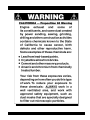
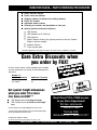
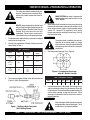
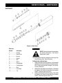
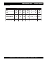
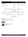
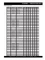
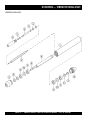
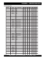
PARTS AND OPERATION MANUAL
STOW VIBRATOR HEADS
© COPYRIGHT 2002, MULTIQUIP INC.
MODELS 900, 1000, 1300,
1400, 1700, 2100 & 2600
MODEL #
SERIAL #
Revision #1 (04/22/02)
STOW CONSTRUCTION EQUIPMENT
PARTS DEPARTMENT:
A DIVISION OF MULTIQUIP INC.
POST OFFICE BOX 6254
CARSON, CA 90749
310-537-3700 • 888-252-STOW [888-252-7869]
FAX: 310-537-1986 • FAX: 800-556-1986
E-MAIL: [email protected] • WWW: stowmfg.com
800-427-1244
FAX: 800-672-7877
SERVICE DEPARTMENT/TECHNICAL ASSISTANCE:
800-478-1244
FAX: 310-631-5032
P/N 36200
HERE'S HOW TO GET HELP
PLEASE HAVE THE MODEL AND SERIAL NUMBER
ON-HAND WHEN CALLING
PARTS DEPARTMENT
800-427-1244 or 310-537-3700
FAX: 800-672-7877 or 310-637-3284
SERVICE DEPARTMENT/TECHNICAL ASSISTANCE
800-478-1244 or 310-537-3700
FAX: 310- 537-4259
WARRANTY DEPARTMENT
888-661-4279, or 310-661-4279
FAX: 310- 537-1173
MAIN
800-421-1244 or 310-537-3700
FAX: 310-537-3927
VIBRATOR HEADS — PARTS & OPERATION MANUAL — REV. #1 (04/22/02) — PAGE 3
VIBRATOR HEADS— TABLE OF CONTENTS
Here's How To Get Help ............................................ 3
Table Of Contents ..................................................... 4
Parts Ordering Procedures ....................................... 5
Safety Message Alert Symbols ................................. 6
Rules For Safe Operation ......................................... 7
MQ STOW - VIBRATOR HEADS
Preparation & Operation ........................................... 8
Maintenance ........................................................ 9-10
Specifications .......................................................... 11
Seal Installation Instructions ................................... 12
Vibrator Head Assembly .................................... 14-17
Terms And Conditions Of Sale ................................ 18
NOTE
Specifications and
part numbers are
subject to change
without notice.
PAGE 4 — VIBRATOR HEADS— PARTS & OPERATION MANUAL — REV. #1 (04/22/02)
VIBRATOR HEADS— PARTS ORDERING PROCEDURES
n
n
n
n
n
n
n
Dealer account number
Dealer name and address
Shipping address (if different than billing address)
Return fax number
Applicable model number
Quantity, part number and description of each part
Specify preferred method of shipment:
•
•
•
•
UPS Ground
UPS Second Day or Third Day*
UPS Next Day*
Federal Express Priority One (please provide us with your Federal
Express account number)*
•
•
Airborne Express*
Truck or parcel post
*Normally shipped the same day the order is received, if prior to 2PM west coast time.
Earn Extra Discounts when
you order by FAX!
ount
All parts orders which include complete part numbers
and are received by fax qualify for the following extra
discounts:
Number of
line items ordered
1-9 items
Additional Discount
3%
10+ items**
5%
Get special freight allowances
when you order 10 or more
line items via FAX!**
n
n
UPS Ground Service at no charge for freight
UPS Third Day Service at one-half of actual freight
cost
No other allowances on freight shipped by any other carrier.
**Common nuts, bolts and washers (all items under $1.00 list price)
do not count towards the 10+ line items.
x Disc
a
F
a
r
A
Ext
tic US
s
e
m
for Do
Only
s
r
e
l
a
De
Now! Direct TOLL-FREE access
to our Parts Department!
Toll-free nationwide:
800-421-1244
Toll-free FAX:
800/6-PARTS-7 • 800-672-7877
*DISCOUNTS ARE SUBJECT TO CHANGE*
Fax order discount and UPS special programs revised June 1, 1995
VIBRATOR HEADS — PARTS & OPERATION MANUAL — REV. #1 (04/22/02) — PAGE 5
VIBRATOR HEADS— SAFETY MESSAGE ALERT SYMBOLS
FOR YOUR SAFETY AND THE SAFETY OF OTHERS!
Safety precautions should be followed at all times when operating
this equipment. Failure to read and understand the Safety
Messages and Operating Instructions could result in injury to
yourself and others.
HAZARD SYMBOLS
Engine exhaust gases contain poisonous
carbon monoxide. This gas is colorless and
odorless, and can cause death if inhaled.
NEVER operate this equipment in a confined
area or enclosed structure that does not
provide ample free flow air.
NOTE
This Owner's Manual has been developed to provide
complete instructions for the safe and efficient operation
of the STOW VIBRATOR HEADS.
Before using this equipment, ensure that the
operating individual has read and understands all
instructions in this manual.
SAFETY MESSAGE ALERT SYMBOLS
The three (3) Safety Messages shown below will inform you
about potential hazards that could injure you or others. The
Safety Messages specifically address the level of exposure to
the operator, and are preceded by one of three words: DANGER,
WARNING, or CAUTION.
DANGER:
You WILL be KILLED or
SERIOUSLY injured if you DO NOT follow
directions.
WARNING:
You CAN be KILLED or
SERIOUSLY injured if you DO NOT follow
directions.
Explosive Fuel
Gasoline is extremely flammable, and its
vapors can cause an explosion if ignited. DO
NOT start the engine near spilled fuel or
combustible fluids. DO NOT fill the fuel tank
while the engine is running or hot. DO NOT
overfill tank, since spilled fuel could ignite if it
comes into contact with hot engine parts or
sparks from the ignition system. Store fuel in
approved containers, in well-ventilated areas
and away from sparks and flames. NEVER
use fuel as a cleaning agent.
Burn Hazards
High Temperatures – Unplug the machine and
allow to cool before performing service and
maintenance functions. Contact with hot!
components can cause serious burns.
Rotating Parts
NEVER operate equipment with covers, or
guards removed. Keep fingers, hands, hair and
clothing away from all moving parts to prevent
injury.
Sight and Hearing hazard
CAUTION:
You CAN be injured if you
DO NOT follow directions.
Potential hazards associated with Stow VIBRATOR HEADS
operation will be referenced with "Hazard Symbols" which
appear throughout this manual, and will be referenced in
conjunction with Safety "Message Alert Symbols".
ALWAYS wear approved eye and hearing
protection.
Accidental Starting
ALWAYS place the motor ON/OFF switch
in the OFF position, when the Vibrator
Motor is not in use.
PAGE 6 — VIBRATOR HEADS— PARTS & OPERATION MANUAL — REV. #1 (04/22/02)
VIBRATOR HEADS— RULES FOR SAFE OPERATION
WARNING:
Failure to follow instructions in this manual may
lead to serious injury or even death! This
equipment is to be operated by trained and
qualified personnel only! This equipment is
for industrial use only.
■ ALWAYS check the equipment for loosened threads or bolts
before starting.
■ NEVER use accessories or attachments, which are not
recommended by Stow for this equipment. Damage to the
equipment and/or injury to user may result.
EMERGENCIES
The following safety guidelines should always be used when
operating this equipment.
■ ALWAYS know the location of
the nearest fire extinguisher.
SAFETY
■ DO NOT operate or service this equipment
before reading this entire manual.
■ ALWAYS use proper lifting techniques when
using the the vibrator motor, flexible shaft
and vibrator head assembly.
■ ALWAYS check to make sure that the operating area is clear
before starting the vibrator motor or engine.
■ ALWAYS know the location of the
nearest and first aid kit.
■ NEVER leave the machine unattended while running.
■ Keep the vibrator motor or engine in proper running condition.
■ Make sure that there is no buildup of concrete, grease, oil or
debris on the equipment.
■ Fix damage to the equipment immediately and always replace
broken parts.
■ This equipment should not be operated by persons under
18 years of age.
■ In emergencys always know the location of the
nearest phone or keep a phone on the job site.
Also know the phone numbers of the nearest
ambulance, doctor and fire department. This
information will be invaluable in the case of an
emergency.
■ NEVER operate this equipment without proper
protective clothing, shatterproof glasses, steeltoed boots and other protective devices required
by the job.
■ NEVER operate this equipment when not feeling
well due to fatigue, illness or taking medicine.
■ NEVER operate this equipment under the
influence or drugs or alcohol.
VIBRATOR HEADS — PARTS & OPERATION MANUAL — REV. #1 (04/22/02) — PAGE 7
VIBRATOR HEADS—PREPARATION & OPERATION
This safety alert symbol is used to attract your
attention. Personal safety is involved. When
you see this symbol, become alert; heed its
message.
WARNING!
MAKE CERTAIN the motor is disconnected
from the power source and the switch is in the
"OFF" position.
WARNING!
4.
1.
CAUTION!
DO NOT attempt to operate this vibrator head
until the Safety and Operating Instructions for
the Electric Motor or Gasoline Power Unit and
Flexible Shaft have been read and fully
understood. Failure to do so could result in
serious bodily injury and/or property damage.
2.
The vibrator motor, flexible shafting, and heads are shipped
from the factory ready to use.
When connecting the head to the casing, clean the mating
threads with an anaerobic sealant primer and allow it to air
dry for several minutes. Apply a ring of anaerobic sealant
(Loctite 271, Hernon 427 or equivalent), to the casing
threads and screw the head tightly to the casing. Wait for
one hour before using.
The vibrator head is cooled by the concrete.
Operation of the vibrator head in air longer
than 2 minutes at a time will cause overheating
of the bearings which will result in premature
head failure.
Use only the combination of flexible shafting and heads
shown below in Table 1.
Table 1. Shaft Sizes
MODEL
SHAFT
HEAD SIZE
MAX. SHAFT
LENGTH
1HP
SV-1, DI 1
75ER
314V
900
1000
1300
21 FT.
1400
1700
28 FT.
2100
21 FT.
1400
1700
2100
2600
35 FT.
2HP
SV-2, DI 2
130 ER
3HP
SV-3, DI3
200 ER
3.
5.
See Compaction Coverage Chart, (Figure 2).
382V
382V
Figure 2. Compaction Coverage
with 50% Radial Overlap
Table 2. Compaction Coverage
To connect the flexible shafting to the vibrator motor see
(Figure 1). (382V Shafting shown)
Head
900
1000
1300
1400
1700
2100
2600
P-Dimension
4"
5-1/2"
8"
8"
12"
14"
18"
6.
Immerse the head for 5 to 10 seconds, (until air stops rising),
and then withdraw it slowly to let the concrete fill the void
left by the head. The head should be completely below the
surface when vibrating to keep the head cool. When
vibrating a thin horizontal slab, the head can be used in a
horizontal position.
CAUTION!
Figure 1. Shafting to Motor Connection
(382V Shafting Shown)
If the shaft begins to helix (buckle) excessively
during operation, stop and investigate. This is
an indication of an overload condition.
PAGE 8 — VIBRATOR HEADS— PARTS & OPERATION MANUAL — REV. #1 (04/22/02)
VIBRATOR HEADS— MAINTENANCE
MAINTENANCE
Figure 3. Head Parts
Reference
Number
Description
1 ....................... Housing
CAUTION!
DO NOT allow the vibrator head to wear below
the following dimensions: See General
Specifications - page11.
2 ....................... Nut or Screw
3 ....................... Bearing
4 ....................... Spindle
5 ....................... Seal
The vibrator heads should be inspected and lubricated after
every 100 hours of use. Refer to (Figure 3).
10 ..................... Shim
To Disassemble a Vibrator Head:
1. Remove the flexible shaft from the head. Heat should be
applied to the threads to break down the anaerobic sealant.
This will help prevent possible damage to the threads.
Threads are left-hand.
11 ..................... Flat Washer
2.
Remove the casing adapter from the housing. Head should
be applied to the threads to break down the anaerobic
sealant. Threads are right-hand. (Ref. 9)
3.
Remove the hardened tip from the housing. Heat should
be applied to the threads to break down the anaerobic
sealant. Threads are right-hand. (Ref. 1,12)
6 ....................... Spacer
8 ....................... Fitting Adapter
9 ....................... Casing Adapter
12 ..................... Tip
VIBRATOR HEADS — PARTS & OPERATION MANUAL — REV. #1 (04/22/02) — PAGE 9
VIBRATOR HEADS — MAINTENANCE
4.
Remove the cap screw or hex nut that holds the lower
bearings in place. (Ref. 2)
5.
Remove the spindle with the upper bearings still attached.
The lower bearings (tip-end) can now be removed from
the housing.(Ref. 4)
6.
Remove and discard the oil seals. Note the way the seals
face so that the new seals will be installed correctly. (Ref. 5)
7.
Thoroughly clean all parts with a degreasing solvent and
blow dry with air. Compressed air is not recommended for
cleaning and drying solvents out of the bearings. Bearings
should never be spun at high speed using compressed air.
(Ref. 3)
8.
After cleaning, inspect all parts for wear. The bearings
should be checked by applying a light thrust load against
one bearing ring, while slowly rotating the other ring. Do
this in both directions. If any roughness or excessive
looseness is felt, the bearing should be replaced. Any
other parts that show heavy wear should also be replaced
at this time. (Ref. 3)
6.
Apply a high strength anaerobic sealant to the external
threads of the casing adapter. Screw the adapter into the
housing and tighten. Threads are left-hand. (Ref. 1,9)
7.
Tip head over and pour in the required amount of Stow
Lube P/N 12000-301. Refer to General Specifications Table
on page 11.
CAUTION!
DO NOT use more than the specified amount
of lubricant in the vibrator head. Over-filling
will cause the head to overheat and lead to
premature failure.
8.
Assemble the lower bearings to the spindle. (Ref. 3)
9.
Clean the tip threads and the mating threads on the housing
with anaerobic sealant primer. Allow to dry. (Ref. 1,12)
10. Apply a high strength anaerobic sealant to the tip threads
and screw the tip into the housing. Threads are right-hand.
(Ref. 1,12)
To Reassemble a Vibrator Head:
Assemble the Head to the Casing:
1.
11. Clean the casing threads and the mating threads on the
head with an anaerobic sealant primer and allow to dry.
Bearing Installation: Bearing installation should take
place under the cleanest possible conditions. Inspect the
spindle bearing seat diameter for nicks and burrs. If any
are found, carefully remove using a stone or fine file. Wipe
the bearing seat diameter with head oil to help prevent
galling while the bearing is being pressed on. While
installing the bearing, the installation force should always
be applied squarely and evenly to the inner race of the
bearing. (Ref. 3)
2.
Seal Installation: Remove any nicks or burrs that will
interfere with the installation of the seal. Make sure the
seal is facing the right direction and that it is properly
positioned so that it will seat squarely without damage.
See illustration on page 12. Use an installation tool that
will apply the force evenly around the outer edge of the
seal.
3.
Insert the spindle with upper bearings assembled on it,
into the housing. Using a light push fit, seat the bearings
into the housing. (Ref. 4)
4.
Insert the seals into the casing adapter per the seal
installation instructions. (See page 12)
5.
Clean the casing adapter external threads and the mating
internal threads on the housing with anaerobic primer and
let dry. (Ref. 1,9)
12. Apply a ring of anaerobic high strength sealand to the casing
threads. Screw the casing into the head and tighten.
13. Allow to set one hour before use.
PAGE 10 — VIBRATOR HEADS— PARTS & OPERATION MANUAL — REV. #1 (04/22/02)
VIBRATOR HEADS — SPECIFICATIONS
SPECIFICATIONS
TABLE 3. GENERAL SPECIFICATIONS
Model
900
1000
1300
1400
1700
2100
2600
Weight
1 lb.
11 oz.
2 lb.
6 oz.
4 lbs.
11 oz.
4 lbs.
10 oz.
6 lbs.
4 oz.
8 lbs.
11 oz.
12 lbs.
10 oz.
Length
15"
14"
15"
15"
14"
13"
13"
Manufacturing Diameter
7/8
1 - 1 /1 6
1 - 3/8
1 - 3/8
1 - 11/16
2 - 1/8
2 - 5/8
Minimum Wear Diameter
13/16
1
1 - 1/4
1 - 1/4
1 - 9 /1 6
1 - 7/8
2 - 1/4
Head Lube Capacity
1/2 oz.
1/2 oz.
1/2 oz.
1/2 oz.
3/4 oz.
1 oz.
1 - 1/2 oz.
VIBRATOR HEADS — PARTS & OPERATION MANUAL — REV. #1 (04/22/02) — PAGE 11
VIBRATOR HEADS — SEAL INSTALLATION
SEAL INSTALLATION
SHAFT END
HEAD END
2.
Seal lip to face vibrator head end.
1.
Seal lip to face vibrator shaft end.
Figure 4. Seal Installation
■ Seal outer case to face outer case of first seal pressed into
casing adapter.
■ Depending on vibrator head model, casing adapter may not
appear exactly as shown.
CAUTION!
Improper seal installation may cause
premature head failure.
PAGE 12 — VIBRATOR HEADS— PARTS & OPERATION MANUAL — REV. #1 (04/22/02)
NOTE PAGE
VIBRATOR HEADS — PARTS & OPERATION MANUAL — REV. #1 (04/22/02) — PAGE 13
SV-SERIES — VIBRATOR HEAD ASSY.
VIBRATOR HEAD ASSY.
PAGE 14 — VIBRATOR HEADS— PARTS & OPERATION MANUAL — REV. #1 (04/22/02)
SV-SERIES — VIBRATOR HEAD ASSY.
VIBRATOR HEAD ASSY.
ITEM NO.
PART NO.
DESCRIPTION
-
17302-505
MODEL 900
-
16369-501
MODEL 1000
-
16317-501
MODEL 1300
-
16316-501
MODEL 1400
-
15699-505
MODEL 1700
-
16301-501
MODEL 2100
-
16274-501
MODEL 2600
1
17303-002
HOUSING
1
16371-001
HOUSING
1
16320-001
HOUSING
1
15700-001
HOUSING
1
16305-001
HOUSING
1
16279-001
HOUSING
2
08233-004
NUT GRIPCO 1/4-20
2
08233-005
NUT GRIPCO 5/16-18
2
08297-006
NUT GRIPCO 3/8-24
2
06511-005
HHCS 3/8-24 x 5/8
2
06513-006
HHCS 1/2-20 x 3/4
3
09189-002
BEARING
3
10093-401
BEARING
3
19393-004
BEARING
3
19393-003
BEARING
3
19393-001
BEARING
3
19393-002
BEARING
4
11199-002
SPINDLE
4
19484-001
SPINDLE
4
18871-001
SPINDLE
4
26900-001
SPINDLE
4
18785-001
SPINDLE
4
18809-001
SPINDLE
900
1000
1300
1400
1700
2100
2600
X
X
X
X
X
X
X
1
1
1
1
1
1
1
1
1
1
1
1
1
1
4
4
4
4
4
4
4
1
1
1
1
1
1
VIBRATOR HEADS — PARTS & OPERATION MANUAL — REV. #1 (04/22/02) — PAGE 15
1
SV-SERIES — VIBRATOR HEAD ASSY.
VIBRATOR HEAD ASSY.
PAGE 16 — VIBRATOR HEADS— PARTS & OPERATION MANUAL — REV. #1 (04/22/02)
SV-SERIES — VIBRATOR HEAD ASSY.
VIBRATOR HEAD ASSY.
ITEM NO.
PART NO.
DESCRIPTION
900
5
07001-056
SEAL
5
07001-021
SEAL
5
07001-029
SEAL
5
07001-046
SEAL
5
07001-057
SEAL
5
07001-019
SEAL
6
26055-001
SPACER
1
8
26050-001
FITTING ADAPTER
1
8
16375-001
FITTING ADAPTER
8
16328-001
FITTING ADAPTER
8
16327-001
FITTING ADAPTER
9
26049-001
CASING ADAPTER
9
16374-002
CASING ADAPTER
9
16325-001
CASING ADAPTER
9
16326-001
CASING ADAPTER
9
16704-001
CASING ADAPTER
9
16303-001
CASING ADAPTER
9
16278-001
CASING ADAPTER
10
11906-025
SHIM
10
11906-012
SHIM
10
11906-015
SHIM
10
11906-020
SHIM
11
07030-006
FLATWASHER 3/8
11
07030-008
FLATWASHER 1/2
12
11204-001
TIP
12
16368-001
TIP
12
16318-001
TIP
12
15705-001
TIP
12
16302-001
TIP
12
16277-001
TIP
1000
1300
1400
2
2
1700
2100
2600
2
2
2
2
2
1
1
1
1
1
1
1
1
1
1
2
2
2
2
2
2
2
1
1
1
1
1
1
1
1
1
VIBRATOR HEADS — PARTS & OPERATION MANUAL — REV. #1 (04/22/02) — PAGE 17
1
TERMS AND CONDITIONS OF SALE
Effective: July 1, 2000
PAYMENT TERMS
4.
Terms of payment for parts are net 10 days.
FREIGHT POLICY
All parts orders will be shipped collect or
prepaid with the charges added to the invoice.
All shipments are F.O.B. point of origin.
Multiquip’s responsibility ceases when a signed
manifest has been obtained from the carrier,
and any claim for shortage or damage must be
settled between the consignee and the carrier.
Freight is at the sender’s expense. All
parts must be returned freight prepaid to
Multiquip’s designated receiving point.
5.
Parts must be in new and resalable
condition, in the original Multiquip package
(if any), and with Muiltiquip part numbers
clearly marked.
6.
The following items are not returnable:
MINIMUM ORDER
a.
Obsolete parts. (If an item is listed
in the parts price book as being
replaced by another item, it is
obsolete.)
b.
Any parts with a limited shelf life
(such as gaskets, seals, “O” rings,
and other rubber parts) that were
purchased more than six months
prior to the return date.
PRICING AND REBATES
Prices are subject to change without prior
notice. Price changes are effective on a specific
date and all orders received on or after that date
will be billed at the revised price. Rebates for
price declines and added charges for price
increases will not be made for stock on hand at
the time of any price change.
Multiquip reserves the right to quote and sell
direct to Government agencies, and to Original
Equipment Manufacturer accounts who use
our products as integral parts of their own
products.
SPECIAL EXPEDITING SERVICE
The minimum charge for orders from Multiquip
is $15.00 net. Customers will be asked for
instructions regarding handling of orders not
meeting this requirement.
c.
Any line item with an extended dealer
net price of less than $5.00.
RETURNED GOODS POLICY
d.
Special order items.
Return shipments will be accepted and credit
will be allowed, subject to the following
provisions:
e.
Electrical components.
f.
Paint, chemicals, and lubricants.
LIMITATIONS OF SELLER’S LIABILITY
g.
Decals and paper products.
h.
Items purchased in kits.
Multiquip shall not be liable here under for
damages in excess of the purchase price of the
item with respect to which damages are claimed,
and in no event shall Multiquip be liable for loss
of profit or good will or for any other special,
consequential or incidental damages.
1.
A Returned Material Authorization must
be approved by Multiquip prior to shipment.
2.
To obtain a Return Material Authorization,
a list must be provided to Multiquip Parts
Sales that defines item numbers,
quantities, and descriptions of the items to
be returned.
a.
3.
The parts numbers and descriptions
must match the current parts price
list.
b.
The list must be typed or computer
generated.
c.
The list must state the reason(s) for
the return.
d.
The list must reference the sales
order(s) or invoice(s) under which
the items were originally purchased.
e.
The list must include the name and
phone number of the person
requesting the RMA.
A copy of the Return Material
Authorization must accompany the return
shipment.
7.
The sender will be notified of any material
received that is not acceptable.
8.
Such material will be held for 5 working
days from notification, pending
instructions. If a reply is not received
within 5 days, the material will be returned
to the sender at his expense.
9.
Credit on returned parts will be issued at
dealer net price at time of the original
purchase, less a 15% restocking charge.
10. In cases where an item is accepted for
which the original purchase document
can not be determined, the price will be
based on the list price that was effective
twelve months prior to the RMA date.
11. Credit issued will be applied to future
purchases only.
A $20.00 to $50.00 surcharge will be added to
the invoice for special handling including bus
shipments, insured parcel post or in cases
where Multiquip must personally deliver the
parts to the carrier.
LIMITATION OF WARRANTIES
No warranties, express or implied, are made in
connection with the sale of parts or trade
accessories nor as to any engine not
manufactured by Multiquip. Such warranties
made in connection with the sale of new,
complete units are made exclusively by a
statement of warranty packaged with such
units, and Multiquip neither assumes not
authorizes any person to assume for it any
other obligation or liability whatever in
connection with the sale of its products. A part
from such written statement of warranty, there
are no warranties, express, implied or statutory,
which extend beyond the description of the
products on the face hereof.
PAGE 18 — VIBRATOR HEADS— PARTS & OPERATION MANUAL — REV. #1 (04/22/02)
NOTE PAGE
VIBRATOR HEADS — PARTS & OPERATION MANUAL — REV. #1 (04/22/02) — PAGE 19
PARTS AND OPERATION MANUAL
HERE'S HOW TO GET HELP
PLEASE HAVE THE MODEL AND SERIAL NUMBER
ON-HAND WHEN CALLING
PARTS DEPARTMENT
800-427-1244 or 310-537-3700
FAX: 800-672-7877 or 310-637-3284
SERVICE DEPARTMENT/TECHNICAL ASSISTANCE
800-478-1244 or 310-537-3700
FAX: 310- 537-4259
WARRANTY DEPARTMENT
888-661-4279, or 310-661-4279
FAX: 310- 537-1173
MAIN
800-421-1244 or 310-537-3700
FAX: 310-537-3927
STOW CONSTRUCTION EQUIPMENT
PARTS DEPARTMENT:
A DIVISION OF MULTIQUIP INC.
POST OFFICE BOX 6254
CARSON, CA 90749
310-537-3700 • 888-252-STOW [888-252-7869]
FAX: 310-537-1986 • FAX: 800-556-1986
E-MAIL: [email protected] • WWW: stowmfg.com
800-427-1244
FAX: 800-672-7877
SERVICE DEPARTMENT/TECHNICAL ASSISTANCE:
800-478-1244
FAX: 310-631-5032