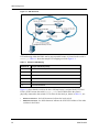
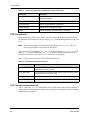
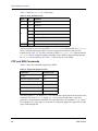
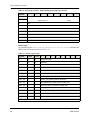
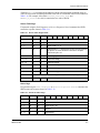
1
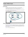
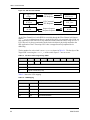
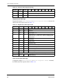
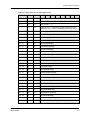
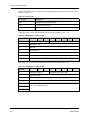
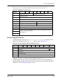
StorageNet Fibre Channel Switch 4000
SES (SCSI-3 Enclosure Services)
User Guide
8946121402
StorageNet Fibre Channel Switch 4000
SES (SCSI-3 Enclosure Services)
User Guide
8946121402
Revision History
Tab Level/Date
Description
01 (08/98)
Initial release.
02 (03/99)
Manual release corresponding to Release 1.6a.
The U.S. Department of Commerce restricts the distribution of technical information contained
in this document when exported outside the U.S. Therefore, careful attention should be given
to compliance with all applicable U.S. Export Laws if any part of this document is to be
exported.
© 1999 Storage Technology Corporation, Louisville, Co. All rights reserved. Printed in USA.
Address comments concerning this manual to:
StorageTek
Technical Communications
7600 Boone Avenue North
Minneapolis, MN 55428-1099
USA
Comments may also be submitted over the Internet by addressing them to:
[email protected]
Always include the complete publication number and title of the document with your
comments.
ii
8946121402
About This Document
Introduction
Use this guide for monitoring, configuring, and maintaining a StorageNet Fibre Channel
Switch 4000 through SCSI-3 Enclosure Services (SES). You should be knowledgeable about
networking in general, routing and bridging in particular. A clearly defined network and
security plan is necessary. Your security plan should assess the possible risks to your network
and define access policies to deal with those risks.
How This Guide is Organized
This guide is divided into the following chapters:
•
Chapter 1 “Product Overview”, provides an overview of SES and SES Management.
•
Chapter 2 “SES Concepts”, describes the concepts associated with SES.
•
Chapter 3 “SES Commands”, describes FC-PH constructs, FCP and SES commands,
and diagnostics pages.
•
Chapter 4 “Troubleshooting”, describes command error messages.
The following appendix is also included in this guide:
•
Appendix A “Glossary”.
Reference Documents
The following documents contain information related to SES:
Fibre Channel Standards. For detailed information on the Fibre Channel standards, see the
Fibre Channel Association web site at http://www.fibrechannel.com.
StorageNet Fibre Channel Switch 4000 Installation and Reference Guide (8946119902)
StorageNet Fibre Channel Switch 4000 WEB TOOLS User Guide (8946121602)
StorageNet Fibre Channel Switch 4000 ZONING User Guide (8946121502)
8946121402
iii
Notice to the Reader
The material contained in this publication is for informational purposes only and is subject to
change without notice. StorageTek is not responsible for the use of any product options or
features not described in this publication, and assumes no responsibility for any errors that
may appear in this publication. Refer to the revision history (at the beginning of this
document) to determine the revision level of this publication.
StorageTek does not by publication of the descriptions and technical documentation contained
herein, grant a license to make, have made, use, sell, sublicense, or lease any equipment or
programs designed or constructed in accordance with this document or programs designed or
constructed in accordance with this information.
Customer Support
For technical support, please call StorageTek at 1-800-248-8777.
Before calling StorageTek, please have your information from the Problem Reporting form
ready. This form is located at the back of this manual.
If a problem cannot be resolved through Customer Support, a Return Material Authorization
(RMA) is issued. Instructions are provided on where to return the part and how to receive a
replacement part. If the product is installed by the customer, the customer is responsible for
returning the product with freight paid to the nearest repair center.
iv
8946121402
Table of Contents
Chapter 1 Product Overview
Introduction . . . . . . . . . . . . . . . . . . . . . . . . . . . . . . . . . . . . . . . . . . . . . . . . . . . . . . . . . . . . . .1-1
SES Management . . . . . . . . . . . . . . . . . . . . . . . . . . . . . . . . . . . . . . . . . . . . . . . . . . . . . . . . .1-1
Chapter 2 SES Concepts
Introduction . . . . . . . . . . . . . . . . . . . . . . . . . . . . . . . . . . . . . . . . . . . . . . . . . . . . . . . . . . . . . .2-1
SES Functional Model . . . . . . . . . . . . . . . . . . . . . . . . . . . . . . . . . . . . . . . . . . . . . . . . . . . . . .2-1
Access to the Enclosure Services Process . . . . . . . . . . . . . . . . . . . . . . . . . . . . . . . . . . . . . .2-3
Access Through an Enclosure Services Device . . . . . . . . . . . . . . . . . . . . . . . . . . . . . . . . . .2-3
Indicators and Control Management . . . . . . . . . . . . . . . . . . . . . . . . . . . . . . . . . . . . . . . . . . .2-3
Chapter 3 SES Commands
Introduction . . . . . . . . . . . . . . . . . . . . . . . . . . . . . . . . . . . . . . . . . . . . . . . . . . . . . . . . . . . . . .3-1
Constructs, Commands and Diagnostic Pages . . . . . . . . . . . . . . . . . . . . . . . . . . . . . . . . . . .3-1
FCP Constructs . . . . . . . . . . . . . . . . . . . . . . . . . . . . . . . . . . . . . . . . . . . . . . . . . . . . . . . . . . .3-2
FCP Command Information Unit . . . . . . . . . . . . . . . . . . . . . . . . . . . . . . . . . . . . . . . . . . .3-2
FCP Transfer Ready Information Unit . . . . . . . . . . . . . . . . . . . . . . . . . . . . . . . . . . . . . . .3-3
FCP Data Information Unit. . . . . . . . . . . . . . . . . . . . . . . . . . . . . . . . . . . . . . . . . . . . . . . .3-3
FCP Response Information Unit . . . . . . . . . . . . . . . . . . . . . . . . . . . . . . . . . . . . . . . . . . .3-3
FCP and SES Commands . . . . . . . . . . . . . . . . . . . . . . . . . . . . . . . . . . . . . . . . . . . . . . . . . . .3-4
Switch Diagnostics Pages . . . . . . . . . . . . . . . . . . . . . . . . . . . . . . . . . . . . . . . . . . . . . . . .3-5
Supported Diagnostics Pages. . . . . . . . . . . . . . . . . . . . . . . . . . . . . . . . . . . . . . . . . .3-5
Switch Page . . . . . . . . . . . . . . . . . . . . . . . . . . . . . . . . . . . . . . . . . . . . . . . . . . . . . . .3-6
Sensor Table Page . . . . . . . . . . . . . . . . . . . . . . . . . . . . . . . . . . . . . . . . . . . . . . . . . .3-7
Fabric Page . . . . . . . . . . . . . . . . . . . . . . . . . . . . . . . . . . . . . . . . . . . . . . . . . . . . . . . .3-7
Neighborhood Table Page . . . . . . . . . . . . . . . . . . . . . . . . . . . . . . . . . . . . . . . . . . . . .3-8
Fibre Channel Port Table Page . . . . . . . . . . . . . . . . . . . . . . . . . . . . . . . . . . . . . . . . .3-8
Name Server Local Table Page. . . . . . . . . . . . . . . . . . . . . . . . . . . . . . . . . . . . . . . .3-10
Inquiry . . . . . . . . . . . . . . . . . . . . . . . . . . . . . . . . . . . . . . . . . . . . . . . . . . . . . . . . . . . . . .3-11
Receive Diagnostic Results . . . . . . . . . . . . . . . . . . . . . . . . . . . . . . . . . . . . . . . . . . . . . .3-13
Report LUNs . . . . . . . . . . . . . . . . . . . . . . . . . . . . . . . . . . . . . . . . . . . . . . . . . . . . . . . . .3-14
Request Sense . . . . . . . . . . . . . . . . . . . . . . . . . . . . . . . . . . . . . . . . . . . . . . . . . . . . . . .3-14
Send Diagnostic. . . . . . . . . . . . . . . . . . . . . . . . . . . . . . . . . . . . . . . . . . . . . . . . . . . . . . .3-15
Test Unit Ready . . . . . . . . . . . . . . . . . . . . . . . . . . . . . . . . . . . . . . . . . . . . . . . . . . . . . . .3-15
Reject. . . . . . . . . . . . . . . . . . . . . . . . . . . . . . . . . . . . . . . . . . . . . . . . . . . . . . . . . . . . . . .3-16
8946121402
v
Chapter 4 Troubleshooting
Introduction . . . . . . . . . . . . . . . . . . . . . . . . . . . . . . . . . . . . . . . . . . . . . . . . . . . . . . . . . . . . . .4-1
License Reject . . . . . . . . . . . . . . . . . . . . . . . . . . . . . . . . . . . . . . . . . . . . . . . . . . . . . . . . .4-1
CHECK CONDITION . . . . . . . . . . . . . . . . . . . . . . . . . . . . . . . . . . . . . . . . . . . . . . . . . . . .4-1
Invalid Field Errors . . . . . . . . . . . . . . . . . . . . . . . . . . . . . . . . . . . . . . . . . . . . . . . . . . . . . .4-1
Appendix A Glossary
vi
8946121402
List of Figures
Figure 1-1
SES Overview . . . . . . . . . . . . . . . . . . . . . . . . . . . . . . . . . . . . . . . . . . . . . . .1-2
Figure 2-1
SES Distribution . . . . . . . . . . . . . . . . . . . . . . . . . . . . . . . . . . . . . . . . . . . . .2-1
Figure 2-2
SES Functional Model . . . . . . . . . . . . . . . . . . . . . . . . . . . . . . . . . . . . . . . . .2-2
8946121402
vii
viii
8946121402
List of Tables
Table 1-1
Example LUN Mapping
Table 2-1
Format of LUN recognized by SESD . . . . . . . . . . . . . . . . . . . . . . . . . . . . . .2-2
Table 2-2
LUN Mapping . . . . . . . . . . . . . . . . . . . . . . . . . . . . . . . . . . . . . . . . . . . . . . .2-2
Table 3-1
Constructs, Commands and Diagnostic Pages . . . . . . . . . . . . . . . . . . . . .3-1
Table 3-2
FCP Information Unit Descriptions . . . . . . . . . . . . . . . . . . . . . . . . . . . . . . .3-2
Table 3-3
FCP_CMND IU Format
Table 3-4
FCP_RSP Format . . . . . . . . . . . . . . . . . . . . . . . . . . . . . . . . . . . . . . . . . . . .3-3
Table 3-5
FCP_STATUS Format . . . . . . . . . . . . . . . . . . . . . . . . . . . . . . . . . . . . . . . . .3-4
Table 3-6
Supported Operation Codes . . . . . . . . . . . . . . . . . . . . . . . . . . . . . . . . . . . .3-4
Table 3-7
Diagnostics Pages . . . . . . . . . . . . . . . . . . . . . . . . . . . . . . . . . . . . . . . . . . . .3-5
Table 3-8
Switch MIB Groups . . . . . . . . . . . . . . . . . . . . . . . . . . . . . . . . . . . . . . . . . . .3-5
Table 3-9
Page Code 0 Format – Supported Diagnostic Pages
Table 3-10
Switch Page Format . . . . . . . . . . . . . . . . . . . . . . . . . . . . . . . . . . . . . . . . . .3-6
Table 3-11
Sensor Table Page Format . . . . . . . . . . . . . . . . . . . . . . . . . . . . . . . . . . . . .3-7
Table 3-12
Format of Fabric Page . . . . . . . . . . . . . . . . . . . . . . . . . . . . . . . . . . . . . . . .3-7
Table 3-13
Neighborhood Table Page Format . . . . . . . . . . . . . . . . . . . . . . . . . . . . . . . .3-8
Table 3-14
Fibre Channel Port Table Page Format . . . . . . . . . . . . . . . . . . . . . . . . . . .3-9
Table 3-15
Format of Name Server Local Table Page . . . . . . . . . . . . . . . . . . . . . . . .3-10
Table 3-16
Inquiry Command Format . . . . . . . . . . . . . . . . . . . . . . . . . . . . . . . . . . . . .3-11
Table 3-17
Inquiry Data Format . . . . . . . . . . . . . . . . . . . . . . . . . . . . . . . . . . . . . . . . .3-11
Table 3-18
Page Codes . . . . . . . . . . . . . . . . . . . . . . . . . . . . . . . . . . . . . . . . . . . . . . . .3-12
Table 3-19
SESD Return Codes for 00h . . . . . . . . . . . . . . . . . . . . . . . . . . . . . . . . . . .3-12
Table 3-20
SESD Return Codes for 80h . . . . . . . . . . . . . . . . . . . . . . . . . . . . . . . . . . .3-12
Table 3-21
SESD Return Codes for 83h . . . . . . . . . . . . . . . . . . . . . . . . . . . . . . . . . . .3-13
Table 3-22
Receive Diagnostic Results Command Format . . . . . . . . . . . . . . . . . . . . .3-13
Table 3-23
Report LUNs Command Format . . . . . . . . . . . . . . . . . . . . . . . . . . . . . . . .3-14
Table 3-24
Reported LUNs Format . . . . . . . . . . . . . . . . . . . . . . . . . . . . . . . . . . . . . . .3-14
Table 3-25
Request Sense Command Format . . . . . . . . . . . . . . . . . . . . . . . . . . . . . .3-14
Table 3-26
Send Diagnostic Command Format . . . . . . . . . . . . . . . . . . . . . . . . . . . . .3-15
Table 3-27
Test Unit Ready Command Format . . . . . . . . . . . . . . . . . . . . . . . . . . . . . .3-15
Table 3-28
Reject Command Format . . . . . . . . . . . . . . . . . . . . . . . . . . . . . . . . . . . . .3-16
8946121402
. . . . . . . . . . . . . . . . . . . . . . . . . . . . . . . . . . . . . . .1-2
. . . . . . . . . . . . . . . . . . . . . . . . . . . . . . . . . . . . . . .3-3
. . . . . . . . . . . . . . . .3-5
ix
x
8946121402
Chapter 1 Product Overview
Introduction
This chapter describes StorageTek’s implementation of SES (SCSI-3 Enclosure Services) on
the StorageNet Fibre Channel Switch 4000.
SES implementation in a SCSI-3-based Host Adapter is up to the adapter manufacturer and
StorageTek cannot determine their implementation. Therefore, the focus of this guide is to
discuss StorageTek’s implementation of SES within the Fabric.
Note: Currently, the SES standard is in DRAFT status and is subject to change. See
“Reference Documents” for a pointer to the SES Standards Committee’s web site.
SES Management
SES is an in-band mechanism for managing devices, such as switches, within a Fabric or other
enclosures. SES commands are used to manage and sense the operational status of the power
supplies, cooling devices, displays, indicators, individual drives, and other non-SCSI elements
installed in a switch (enclosure). The command set uses the SCSI SEND DIAGNOSTIC and
RECEIVE DIAGNOSTIC RESULTS commands to obtain/set configuration information from
the switch.
SES allows a SCSI entity (or initiator) to communicate with a switch through a standard Fiber
Channel Protocol (FCP) connection into the Fabric. The benefits are:
•
SES does not require supporting another protocol
•
SES does not require an additional network link (such as Ethernet)
Figure 1-1 shows the Fabric SES view. The switch’s Domain_ID is used as the Logical Unit
Number (LUN) address to identify each switch including the switch used for access through
SES. See the “SES Functional Model” section in Chapter 2 for more information.
Note: The connection to the Fabric is through the switch labeled LUN5 and which is also
called LUN0. The connection to the well known management address (FFFFFAh) is
always labeled LUN0 no matter which switch is used.
8946121402
1-1
SES Management
Figure 1-1 SES Overview
LUN addressing within the Fabric can be non-sequential because it is based on the switch’s
Domain_ID. Table 1-1 shows the sample LUN mapping used with Figure 1-1.
Table 1-1 Example LUN Mapping
Domain ID
Unique LUN Value (in Hex)
5
00000000 00000000 (Note that Domain ID 5 is used for both LUN 0 and 5)
2
01020000 00000000
5
01050000 00000000
6
01060000 00000000
9
01090000 00000000
10
010A0000 00000000
Figure 1-1 shows that the switch in the lower left hand corner is assigned both LUN5 and
LUN0. (LUN5 because the switch’s Domain_ID is 5 and LUN0 because the client is
physically connected to that switch.) LUN values for the first byte, shown in Table 1-1, are:
1-2
•
00000000 00000000
•
0X0X0000 00000000 - the bold characters indicate the SCSI LUN address of the other
switches in the Fabric
- the bold characters indicate the local switch
8946121402
SES Management
Therefore, if there are 5 switches in the Fabric SES reports 6 LUNs, one LUN value for each
switch and LUN0 for the local client connection.
Other SCSI-3 enclosures can also run SES outside the Fabric, such as JBODs, RAID-5 arrays,
SCSI-3 hard drives, and SCSI-3 tape drives. These devices are identified by their Fabric and
SCSI addresses, and are assigned LUNs using standard SCSI-3 host adapter LUN addressing.
Note: It is not this guide’s intent to describe the environment outside of the Fabric.
8946121402
1-3
SES Management
1-4
8946121402
Chapter 2 SES Concepts
Introduction
This chapter uses generic terms to describe enclosure services and specific SES
implementation. SES instances can be distributed inside and outside of the Fabric to any
enclosure capable of supporting enclosure services through an SES device.
SES is distributed transparently throughout the Fabric, with an instance of a distributed SES
Device (SESD) on each switch as shown in Figure 2-1.
Figure 2-1 SES Distribution
SES Functional Model
Each instance may be accessed by an SES Application Client by specifying the associated
unique LUN. See Figure 2-2 for information on LUN addressing. SES implementation also
provides an SES Application Client an in-band mechanism for managing any Fabric switch
that it is attached to.
Figure 2-2 shows the SES functional model.
8946121402
2-1
SES Functional Model
Figure 2-2 SES Functional Model
SES Application
Client
SES Request
SES Response
SES Device
FCP Port
FCP Command
FCP Response
FCP _Port
Request Sequence
Response Sequence
FC-PH
FC-PH
At the Fibre Channel level, each SESD is accessible through the Fibre Channel well known
address, FFFFFAh (Management Server). At the SCSI-3 level, it is associated with a LUN. An
SES Application Client can refer to any distributed SESD within the Fabric using its LUN. A
LUN value of 0 is always associated with the local switch that is physically attached to the
SES Application Client. The unique LUN value is mapped based on peripheral device
addressing.
The bus number for each switch is set to 010000b as shown in Table 2-1. The first byte of the
Target/LUN is set using the Domain_ID of the switch. Bytes 2..7 are set to zero.
Table 2-1 Format of LUN recognized by SESD
Byte/Bit
7
6
5
4
3
0
0
0
Bus Number = 010000b
1
Target
...
or
7
Logical Unit Number (LUN)
2
1
0
Table 2-2 shows the LUN mapping.
Table 2-2 LUN Mapping
Domain ID
2-2
Unique LUN Value (in Hex)
0
0h
01000000 00000000
5
5h
01050000 00000000
12
Ch
010C0000 00000000
15
Eh
010F0000 00000000
25
19h
01190000 00000000
8946121402
Access to the Enclosure Services Process
An SES Application Client may easily find the LUN values of all distributed SESDs inside the
Fabric by using the Report LUNs command. See the “Report LUNs” section in Chapter 3 for
more information.
Access to the Enclosure Services Process
An application client can monitor all enclosures capable of processing the enclosure services
command set with SES instances distributed throughout a Storage Area Network (SAN).
Enclosure services can monitor both devices inside and outside of the enclosure, such as an
Uninterruptable Power Supply (UPS). However, SES pertains only to SES instances inside the
Fabric.
An application client connects through Fiber Channel Protocol (FCP) using the Management
Service address (FFFFAh) to any switch through its LUN. See Figure 1-1. The enclosure
services command set uses the RECEIVE DIAGNOSTIC RESULTS and SEND DIAGNOSTIC
commands to any device capable of supporting SES.
Access Through an Enclosure Services Device
The Application Client requests information from the SESD to examine status and warning
information from the switch.
An Application Client through FCP calls the enclosure services process running on any switch
as a LUN that has SES enabled. The SESD sets the enclosure services bit (EncServ) in the
INQUIRY command to indicate that it can transport enclosure services information. See the
“Inquiry” section in Chapter 3 for more information.
Indicators and Control Management
SESD is accessed through an application client that uses the SEND DIAGNOSTIC command to
transport control information to the enclosure services process. The control information may
include operations to perform or to modify its operating mode. The application client uses the
RECEIVE DIAGNOSTIC RESULTS command with the PF bit set to obtain enclosure status.
The information returned indicates the actual enclosure state. See the “Receive Diagnostic
Results” section in Chapter 3 for more information.
Note: The instructions from the application client may be ignored or overwritten by the
enclosure service processor to ensure proper state information. For example, the
enclosure may ignore an instruction to clear an error condition because the condition
is valid or because the instruction is not supported by the enclosure.
8946121402
2-3
Indicators and Control Management
2-4
8946121402
Chapter 3 SES Commands
Introduction
This chapter contains information and examples on managing SES, including the following:
•
FC-PH constructs
•
FCP and SES commands
•
Diagnostics pages
Note: SESD can be accessed from any Fabric switch licensed to run SES.
Constructs, Commands and Diagnostic Pages
Table 3-1 summarizes the FC-PH constructs, FCP commands, and SES commands.
Table 3-1 Constructs, Commands and Diagnostic Pages
8946121402
Command
Description
FCP Information Unit
SCSI Command to be executed or a task management request.
FCP Transfer Ready
Information Unit
Contains SCSI-3 data delivery service parameters.
FCP Data Information Unit
Transfers data.
FCP Response Information
Unit
Contains status and sense information.
Supported Diagnostics Pages
Contains the diagnostic pages supported.
Switch Page
Contains status information about the switch, its operational state
and firmware.
Sensor Table Page
Contains status information about the state of all sensors in the
switch.
Fabric Page
Contains information about the Fabric, its neighbors and
domain_ID.
Neighborhood Table Page
Contains information about the switch’s neighbors in the Fabric.
Fibre Channel Port Table Page
Contains information about the switch’s Fibre Channel ports.
Name Server Local Table Page
Contains information about the SESD.
Inquiry
Contains information about the devices and sensors in an
enclosure.
Receive Diagnostics Results
Contains information returned by the SESD about an enclosure.
3-1
FCP Constructs
Table 3-1 Constructs, Commands and Diagnostic Pages (Continued)
Command
Description
Report LUNs
Contains information returned from SESD containing the LUNs
attached to the SESD.
Request Sense
Used to sense information from the SESD.
Send Diagnostic
Used to configure/diagnose a logical unit.
Test Unit Ready
Used to test an LUNs operation state.
Reject
Contains information and status about a unit’s failure.
FCP Constructs
Before initiating any FCP request, the Nx_Port associated with the SES Application Client
(FCP Initiator) must complete an N_Port Login (PLOGI) with the Management Server in Class
2 or 3.
Note: The destination address in the PLOGI request must be set to FFFFFAh. The FCP
Process Login (PRLI) is not required by the SESD.
The format of an FCP Command (FCP_CMND), FCP Transfer Ready (FCP_XFER_RDY), FCP
Data (FCP_DATA) and FCP Response (FCP_RSP) conforms to those defined in the SCSI-3
Fibre Channel Protocol (FCP), Revision 12, X3T10/269, working draft.
Table 3-2 gives a brief description of the FCP Information Unit.
Table 3-2 FCP Information Unit Descriptions
FCP Information Unit
Description
FCP_CMND
The Information Unit contains a SCSI Command to be executed or a task
management request on a target.
FCP_XFER_RDY
The Information Unit indicates that the target is ready to perform the data
transfer associated with a FCP_CMD.
FCP_DATA
The data associated with an I/O operation.
FCP_RSP
The Information Unit contains status and sense information
FCP Command Information Unit
Table 3-3 shows the FCP_CMND Information Unit (IU) that carries either a SCSI command to
be executed or a task management request to be performed. It contains the values and control
fields defined in its payload.
3-2
8946121402
FCP Constructs
Table 3-3 FCP_CMND IU Format
Byte Size
Field Name
Byte Number
Description
8
FCP_LUN
0-7
Logical Unit Number
4
FCP_CNTL
8 - 11
Control flags and bits for task/execution management
16
FCP_CDB
12 - 27
SCSI command descriptor block
4
FCP_DL
28 - 31
Data Length
The FCP_LUN value format is described in Table 3-3 or the value is 0. The latter refers to the
SESD on the local switch. The FCP_CNTL value is set to 1, 2 or 0 depending on whether
READ DATA, WRITE DATA or neither is involved in the command. The FCP_CDB value
contains the appropriate command descriptor. The FCP_DL field contains a count of the
maximum number of data bytes to be transferred to or from the target for the command.
FCP Transfer Ready Information Unit
The FCP_XFER_RDY Information Unit contains SCSI-3 data delivery service parameters
required by the initiator and must be transmitted preceding each read or write FCP_DATA IU.
Note: The SESD does not generate this optional Information Unit.
FCP Data Information Unit
The FCP_DATA Information Unit transfers the actual data.
FCP Response Information Unit
Table 3-4 shows the FCP_RSP that carries the response status and sense information associated
with a particular FCP_CMND.
Table 3-4 FCP_RSP Format
8946121402
Byte Size
Field Name
Description
8
Reserved
Reserved
4
FCP_STATUS
Status of the (linked/previous) request
4
FCP_RESID
Residual Count
4
FCP_SNS_LEN
Length of Sense Information (FCP_SNS_INFO)
4
FCP_RSP_LEN
Length of Response Information (FCP_RSP_INFO)
m
FCP_RSP_INFO
FCP Response Information
n
FCP_SNS_INFO
SCSI Sense Information
3-3
FCP and SES Commands
Table 3-5 shows the FCP_STATUS field format.
Table 3-5 FCP_STATUS Format
Byte
Bit
Definition
0
7 .. 0
Reserved
1
7 .. 0
Reserved
7 .. 4
Reserved
3
FCP_RESID_UNDER
2
FCP_RESID_OVER
1
FCP_SNS_LEN_VALID
0
FCP_RSP_LEN_VALID
7 .. 0
SCSI status byte from the SCSI logical unit (not used)
2
3
The reserved bits are set to 0 by the SESD. FCP_RESID_UNDER indicates that the FCP_RESID
field is valid and contains the number of bytes expected to be transferred, but were not
transferred. See Table 3-4. This bit is not used by SESD. FCP_RESID_OVER indicates that the
FCP_RESID field is valid and contains the number of bytes that have been truncated because
the FCP_DL was not sufficient. See Table 3-3. This bit may be set by SESD.
FCP and SES Commands
Table 3-6 shows the commands supported by SESD.
Table 3-6 Supported Operation Codes
Command
Operation Code
Inquiry
12h
Receive Diagnostics Results
1Ch
Report LUNs
A0h
Request Sense
03h
Send Diagnostic
1Dh
Test Unit Ready
00h
The value of the FCP_LUN field in FCP_CMND specifies the logical unit for the request in each
command. The value of FCP_DL field in FCP_CMND specifies whether there is any data
parameter to be transferred to the SESD. The value should be 0 for command 1, 2, 3, 4 and 6.
For command 5, the value may be 0 or the size of a diagnostic page whose page code is in the
range of 80h through 85h.
3-4
8946121402
FCP and SES Commands
Switch Diagnostics Pages
Before each SCSI command is discussed in detail, the diagnostics pages are defined in
Table 3-7. They are particularly relevant to two commands: Receive Diagnostic
Results and Send Diagnostics. The switch SESD supports 7 diagnostics pages.
Table 3-7 Diagnostics Pages
Page Code
Description
00h
Supported Diagnostics Pages
80h
Switch Page
81h
Sensor Table Page
82h
Fabric Page
83h
Neighborhood Table Page
84h
Fibre Channel Port Table Page
85h
Name Server Local Table Page
Table 3-8 shows the page codes 80h through 85h which are vendor specific pages and are
roughly mapped from the switch Management Information Base (MIB) Definition for v1.6a
firmware.
Table 3-8 Switch MIB Groups
Page Code
Switch MIB Group
80h
System Group, variables 1..8, 20, 21
81h
System Group, Sensor Table
82h
Fabric Group, variables 1, 2 and 8
83h
Fabric Group, Neighborhood Table
84h
Fibre Channel Port Table
85h
Name Server Local Table
Supported Diagnostics Pages
If requested using the Send Diagnostic or Receive Diagnostic Result command, the
SESD returns the response shown in Table 3-9
Table 3-9 Page Code 0 Format – Supported Diagnostic Pages
8946121402
Byte/Bit
7
6
0
Page Code = 00h
1
Reserved
5
4
3
2
1
0
3-5
FCP and SES Commands
Table 3-9 Page Code 0 Format – Supported Diagnostic Pages (Continued)
Byte/Bit
7
2
(MSB)
6
3
5
4
3
2
1
Page Length = 7
4
00h
5
80h
6
81h
7
82h
8
83h
9
84h
10
85h
0
(LSB)
Switch Page
If requested using the Send Diagnostic or Receive Diagnostic Result command, the
SESD returns the response shown in Table 3-10.
Table 3-10 Switch Page Format
Byte/Bit
Field #
Access
7
6
5
4
3
2
0
na
na
Page Code = 80h
1
na
na
Reserved
2 .. 3
na
na
Page Length = 404
4 .. 7
na
na
swValid
8 .. 71
0
ro
Current_Date (in ASCII text)
72 .. 135
1
ro
Boot_Date (in ASCII text)
136 .. 199
2
ro
Firmware_Last_Updated_Date (in ASCII text)
200 .. 263
3
ro
FLASH_Last_Updated_Date (in ASCII text)
264 .. 327
4
ro
Boot_PROM_Last_Updated_Date (in ASCII text)
328 .. 391
5
ro
Firmware_Version_Information (in ASCII text)
392 .. 395
6
ro
Switch_Operational_Status
396 .. 399
7
rw
Switch_Administrative_Status
400 .. 403
8
ro
Diagnostics_Result
404 .. 407
9
ro
Number_of_Sensors
1
0
Note: na is not available, ro is read only and rw is read/write
3-6
8946121402
FCP and SES Commands
The field swValid is bit mapped and indicates which subsequent fields within the page are
valid. The bit position for subsequent fields starts from 0, as indicated in the Field # column of
Table 3-10. For example, if the fields: Current_Date, Boot_Date and
Number_of_Sensors are valid, it contains the hex value of 0003h.
Sensor Table Page
If requested using the Send Diagnostic or Receive Diagnostic Result command, the SESD
returns the response shown in Table 3-11.
Table 3-11 Sensor Table Page Format
Byte/Bit
Field #
Access
7
6
5
4
3
2
1
0
0
na
na
Page Code = 81h
1
na
na
Reserved
2 .. 3
na
na
Page Length = n - 3
4 .. 7
na
na
swNumEntries = i – specifies the number of entries received
for bytes 8 -91, if the number is 5 there are 5 complete
outputs for byte 8 - 91.
8 .. 11
na
ro
swValidity[0]
12 .. 15
0
ro
swSensorIndex[0]
16 .. 19
1
ro
swSensorType[0]
20 .. 23
2
ro
swSensorStatus[0]
24 .. 27
3
ro
swSensorValue[0]
28 .. 91
4
ro
swSensorInfo[0]
..
... more instances of swSensorEntry (swValidity .. swSensorInfo) if applicable ...
(n-64)..(n-1)
4
swSensorInfo[i-1]
ro
Fabric Page
If requested using the Send Diagnostic or Receive Diagnostic Result command, the
SESD returns the response shown in Table 3-12.
Table 3-12 Format of Fabric Page
8946121402
Byte/Bit
Field #
Access
7
6
5
0
na
na
Page Code = 82h
1
na
na
Reserved
2 .. 3
na
na
Page Length = 20
4 .. 7
na
na
swValid
8 .. 11
0
ro
swDomainID
4
3
2
1
0
3-7
FCP and SES Commands
Table 3-12 Format of Fabric Page (Continued)
Byte/Bit
Field #
Access
7
6
5
4
12 .. 15
1
ro
PrincipalSwitchFlag
16 .. 19
2
ro
NumberOfImmediateNeighbor
20 .. 23
3
ro
NumberOfFabricISL_Entries
3
2
1
0
Neighborhood Table Page
If requested using the Send Diagnostic or Receive Diagnostic Result command, the
SESD returns the response shown in Table 3-13.
Table 3-13 Neighborhood Table Page Format
Byte/Bit
Field #
Access
7
0
na
na
Page Code = 83h
1
na
na
Reserved
2 .. 3
na
na
Page Length = n - 3
4 .. 7
na
na
swNumEntries = i – specifies the number of entries received
for bytes 8. Note that each entry consists of swValidity[0] field
through field 5.
8 .. 11
na
rw
swValidity[0]
12 .. 15
0
ro
swNbIndex[0]
16 .. 19
1
ro
NswNbMyPort[0]
20 .. 23
2
ro
swNbRemoteDomainID[0]
24 .. 27
3
ro
swNbRemotePort[0]
28 .. 31
4
ro
swNbBaudRate[0]
32 .. 35
5
ro
swNbIslState[0]
..
... more instances of swNbEntry (swValidity .. swNbIslState) if applicable ...
(n-4)..(n-1)
0-5
ro
6
5
4
3
2
1
0
swNbIslState[i-1]
Fibre Channel Port Table Page
If requested using the Send Diagnostic or Receive Diagnostic Result command,
the SESD returns the response shown in Table 3-14.
3-8
8946121402
FCP and SES Commands
Table 3-14 Fibre Channel Port Table Page Format
8946121402
Byte/Bit
Field #
Access
7
6
5
4
3
2
1
0
0
na
na
Page Code = 84h
1
na
na
Reserved
2 .. 3
na
na
Page Length = n - 3
4 .. 7
na
na
swNumEntries = i – specifies the number of entries received.
Note: Each entry consists of swValidity[0] field through field 27.
8 .. 11
na
rw
swValidity[0]
12 .. 15
0
ro
swFCPortIndex[0]
16 .. 19
1
ro
swFCPortType[0]
20 .. 23
2
ro
swFCPortPhyStatus[0]
24 .. 27
3
ro
swFCPortOpStatus[0]
28 .. 31
4
rw
swFCPortAdmStatus[0]
32 .. 35
5
ro
swFCPortTxWords[0]
36 .. 39
6
ro
swFCPortRxWords[0]
40 .. 43
7
ro
swFCPortTxFrames[0]
44 .. 47
8
ro
swFCPortRxFrames[0]
48 .. 51
9
ro
swFCPortTxC2Frames[0]
52 .. 55
10
ro
swFCPortTxC3Frames[0]
56 .. 59
11
ro
swFCPortRxLCs[0]
60 .. 63
12
ro
swFCPortRxMcasts[0]
64 .. 67
13
ro
swFCPortTooManyRdys[0]
68 .. 71
14
ro
swFCPortNoTxCredits[0]
72 .. 75
15
ro
swFCPortRxEncInFrs[0]
76 .. 79
16
ro
swFCPortRxCrcs[0]
80 .. 83
17
ro
swFCPortRxTruncs[0]
84 .. 87
18
ro
swFCPortRxTooLongs[0]
88 .. 91
19
ro
swFCPortRxBadEofs[0]
92 .. 95
20
ro
swFCPortRxEncOutFrs[0]
96 .. 99
21
ro
swFCPortRxBadOs[0]
100 .. 103
22
ro
swFCPortRxC3Discards[0]
104 .. 107
23
ro
swFCPortMcastTimedouts[0]
3-9
FCP and SES Commands
Table 3-14 Fibre Channel Port Table Page Format (Continued)
Byte/Bit
Field #
Access
7
108 .. 111
24
ro
swFCPortTxMcasts[0]
112 .. 115
25
ro
swFCPortLipIns
116 .. 119
26
ro
swFCPortLipOuts
120 .. 123
27
ro
swFCPortLipLastAlpa
..
... more instances of swFCPortEntry (swValidity .. swFCPortTxMcasts) if applicable ...
(n-4)..(n-1)
0 - 27
ro
6
5
4
3
2
1
0
swFCPortLipLastAlpa[i-1]
Name Server Local Table Page
If requested using the Send Diagnostic or Receive Diagnostic Result command, the
SESD returns the following response as shown in Table 3-15.
Table 3-15 Format of Name Server Local Table Page
Byte/Bit
Field #
Access
7
0
na
na
Page Code = 85h
1
na
na
Reserved
2 .. 3
na
na
Page Length = n - 3
4 .. 7
na
na
swNumEntries = i – Note that each entry consists of swValidity[0]
field through field 10.
8 .. 11
na
ro
swValidity[0]
12 .. 15
0
ro
swNsIndex[0]
16 .. 19
1
ro
swNsPortType[0]
20 .. 23
2
ro
swNsPortID[0]
24 .. 31
3
ro
swNsPortName[0]
32 .. 287
4
ro
swNsPortSymbolicName[0]
288 .. 295
5
ro
swNsNodeName[0]
296 .. 551
6
ro
swNsNodeSymbolicName[0]
552 .. 559
7
ro
swNsInitialProcessInitiator[0]
560 .. 575
8
ro
swNsClassOfServices[0]
576 .. 579
9
ro
swNsClassOfServices[0]
580 .. 643
10
ro
swNsFc4Types[0]
...
(n-4)..(n-1)
3-10
6
5
4
3
2
1
0
... more instances of swNsLocalEntry (swValidity..swNsFc4Types) if applicable ...
0 - 10
ro
swNsFc4Types[i-1]
8946121402
FCP and SES Commands
Inquiry
An SES Application Client may send an Inquiry command to obtain information about a
switch in the Fabric. The format of the FCP_CDB is shown in Table 3-16.
Table 3-16 Inquiry Command Format
Byte/Bit
7
6
5
0
Operation Code = 12h
1
Reserved
2
Page Code = 0
3
Reserved
4
Allocation Length
5
Control = 0
4
3
2
1
0
CmdDt=0
EVPD=0
If the field, EVPD (Enable Vital Product Data) is set to 0 and the value of the page code is 0,
the standard Inquiry Data is returned as shown in Table 3-17.
Table 3-17 Inquiry Data Format
8946121402
Byte/Bit
7
6
5
4
3
2
1
0
0
Peripheral Qualifier = 0
1
RMB=
0
2
ISO version = 0
3
AERC
=0
4
Additional Length = 31 (1Fh)
5
Reserved
7
Reser
ved
EncServ
=1Bh
7
RelAdr
=0
WBus32
=0
8 ..15
Vendor identification = ”STORAGETEK”
16. 31
Product identification = “Switch”
32. 35
Product revision level = “v{N}.{m}{p”” (where {N} is a single number designating the major
release number, {m} is a single number designating the minor release number), and {p}
is a single alpha character designating a patch. There may be a space indicating there’s
no patch. For example, v1.5a
Peripheral Device Type = 0Dh
Reserved = 0
TrmTsk=
0
ECMA version = 0
NormAC
A=1
ANSI version = 3
Reserv
ed=0
Response data format = 2
VS = 0
MultiP
=1Bh
MChngr
=0
ACKREQ
Q=0
Addr32
=0
Addr16
=0
Wbus16
=0
Sync=
0
Linked=
0
Trandis=
0
CmdQu
e=0
VS=0
3-11
FCP and SES Commands
If the field, EVPD is set to 1, then the value of the page code may be set to one of the codes
shown in Table 3-18.
Table 3-18 Page Codes
Page Code
Description
00h
Supported vital product data pages
80h
Unit Serial Number Page
83h
Device Identification Page
If the page code is set to 00h, the SESD will return codes shown in Table 3-19.
Table 3-19 SESD Return Codes for 00h
Byte/Bit
7
6
0
Peripheral qualifier = 0
1
Page Code = 00h
2
Reserved
3
Page length = 3
4
00h
5
80h
6
83h
5
4
3
2
1
0
Peripheral Device Type = 0Dh
If the page code is set to 80h, the SESD will return codes shown in Table 3-20.
Table 3-20 SESD Return Codes for 80h
Byte/Bit
7
0
Peripheral qualifier = 0
1
Page Code = 80h
2
Reserved
3
Page length = 24
4
Product Serial Number = the switch World_wide Name in ASCII string format
E.g. “10:00:00:60:69:00:01:b4 ”
...
6
5
4
3
2
1
0
Peripheral Device Type = 0Dh
27
3-12
8946121402
FCP and SES Commands
If the page code is set to 83h, the SESD will return codes shown in Table 3-21.
Table 3-21 SESD Return Codes for 83h
Byte/Bit
7
0
Peripheral qualifier = 0
1
Page Code = 83h
2
Reserved
3
Page length = 32
4
Reserved = 0
Code set = 2
5
Reserved = 0
Identifier type = 1
6
Reserved = 0
7
Identifier length = 28
8
Identifier = Vendor Identification (8 bytes) + Product identification (16 bytes) +
Product revision level (4 bytes)
See Table 3-17.
...
6
5
4
3
2
1
0
Peripheral Device Type = 0Dh
35
Receive Diagnostic Results
An SES Application Client sends a Receive Diagnostic Results command to return
diagnostic or management data. The FCP_CDB format is shown in Table 3-22.
Table 3-22 Receive Diagnostic Results Command Format
Byte/Bit
7
6
5
0
Operation Code = 1Ch
1
Reserved
2
Page Code
3 .. 4
Allocation Length
5
Control = 0
4
3
2
1
0
PCV
A Page Code Valid (PCV) bit of zero indicates that the most recent Send Diagnostic
command defines the data returned by this command. A value of 1 indicates that the Page
Code field defines the data to be returned for this command. The page codes and formats are
defined in the “Switch Diagnostics Pages” section.
8946121402
3-13
FCP and SES Commands
Report LUNs
An SES Application Client sends a Report LUNs command to obtain the number of logical
units (each is a switch in SCSI impersonation) in the Fabric. The CDB format is shown in
Table 3-23.
Table 3-23 Report LUNs Command Format
Byte/Bit
7
6
5
0
Operation Code = A0h
1 .. 5
Reserved
6 .. 9
Allocation Length
10
Reserved
11
Control = 0
4
3
2
1
0
The SESD reports the LUNs of associated switches with the format shown in Table 3-24.
Table 3-24 Reported LUNs Format
Byte/Bit
7
6
0 .. 3
LUN list length (n-7)
4 .. 7
Reserved
8 .. 15
LUN
..
..
(n-7)..n
LUN
5
4
3
2
1
0
Request Sense
An SES Application Client sends a Request Sense command to obtain sense data. The CDB
format is shown in Table 3-25.
Table 3-25 Request Sense Command Format
Byte/Bit
7
6
5
0
Operation Code = 03h
1 .. 3
Reserved
4
Allocation length
5
Control = 0
4
3
2
1
0
The SESD returns a sense key of NO SENSE and an additional sense code of NO ADDITIONAL
SENSE INFORMATION.
3-14
8946121402
FCP and SES Commands
Send Diagnostic
A SES Application Client can use a Send Diagnostic command to configure/diagnose a
logical unit. After the command completion, the SES Application Client sends a Receive
Diagnostic Results command. See Table 3-22. The FCP_CDB format is shown in
Table 3-26.
Table 3-26 Send Diagnostic Command Format
Byte/Bit
7
6
5
0
Operation Code = 1Dh
1
Reserved
2
Reserved
3 .. 4
Parameter list length
5
Control = 0
4
3
2
1
0
PF
Reserved
selfTest
DevOfL
UnitOfL
A Page Format (PF) bit of 1 specifies that the Send Diagnostic parameters conform to the
page structure as specified in SCSI-3 Primary Command (SPC), Revision 11a, X3T10/995D,
working draft. A value of 0 specifies that all parameters are vendor specific. At present, the
SESD only supports the vendor-specific page structures as defined in the “Switch Diagnostics
Pages” section.
The selfTest, DevOfL and UnitOfL bits are ignored by the SESD at present.
The Parameter List Length field specifies the length in bytes of the parameter list that shall be
transferred from the SES Application client to the SESD.
Test Unit Ready
An SES Application Client sends a Test Unit Ready command to check if the logical unit
is ready. The FCP_CDB format is shown in Table 3-27.
Table 3-27 Test Unit Ready Command Format
Byte/Bit
7
6
5
0
Operation Code = 00h
1 .. 4
Reserved
5
Control = 0
4
3
2
1
0
The SESD returns the status of GOOD and CHECK CONDITION and a sense key of NO SENSE
and an additional sense code of NO ADDITIONAL SENSE INFORMATION.
8946121402
3-15
FCP and SES Commands
Reject
The SESD issues a Reject command to set status to Check Condition and the appropriate
values for the Sense Key (SK) field. Additional Sense Code (ASC) and Additional Sense Code
Qualifier (ASCQ) values are as shown in Table 3-28.
Table 3-28 Reject Command Format
3-16
SK
ASC
ASCQ
Explanation
2
04h
0
Logical Unit not ready
2
35h
0
Enclosure Service failed
2
35h
2
Enclosure Service unavailable (memory allocation problem)
5
1Ah
0
Parameter List length error (too small or too big)
5
20
0
Invalid command operation code
5
20
0
Logical Unit not supported (invalid LUN value in FCP_CDB)
8946121402
Chapter 4 Troubleshooting
Introduction
This chapter discusses the SEND DIAGNOSTIC command error messages.
License Reject
A license reject is generated when the SES license key is improperly entered or is not
installed.
The following message is generated:
Probable cause: Invalid Field
Action: See the “Reject” section in Chapter 3 for more information.
CHECK CONDITION
CHECK CONIDITION is generated when the SES Device (SESD) terminates an operation
because an error was encountered. These error conditions can be from invalid operations,
warning indications and failure conditions. The sense key and sense code describe the error.
Invalid Field Errors
ILLEGAL REQUEST is generated from any invalid fields in the CDB, from parameters of a
SEND DIAGNOSTIC command and from the CDB of a RECEIVE DIAGNOSTIC RESULTS
command. The sense code identifies the location of the invalid fields, parameter or CDB.
The following message is generated:
Probable cause: Invalid Field
Action: See the “Reject” section in Chapter 3 for more information.
8946121402
4-1
Introduction
4-2
8946121402
Appendix A Glossary
Application Client: The source object of the SCSI commands and destination for the
command responses.
Byte: A group of 8 bits.
Command Descriptor Block: The structure of up to 16 bytes in length used to communicate
commands from the application client to a device server.
Critical Condition: An enclosure condition where one or more elements inside the enclosure
have failed or are outside of operational parameters. The element failure makes normal
operation of at least some elements in the enclosure impossible, although some of the
elements inside the enclosure may be able to continue normal operation.
Device: A mechanical, electrical or electronic part in an enclosure.
Device Server: A logical unit object that executes SCSI tasks.
Device Service Request: A request from an application client of SCSI commands to a device
server.
Device Slot: An insertion position in an enclosure for SCSI devices. The position provides
power, signal and control connections for the SCSI device. The position may also provide
protection, automatic insertion, device status LEDs, locking capability, and additional
features to manage SCSI devices in the enclosure.
Device Type: The device type or device model implemented by the device server.
Domain_ID: The domain number uniquely identifies the switch in a Fabric. Normally the
switch domain ID is automatically assigned by the principal switch and may be any value
between 0 and 31. This number may also be assigned manually.
Enclosure: The box, rack or box set that provide power, mechanical protection, external
interfaces and cooling for the SCSI device(s).
Enclosure Services: The services that establishes indictors and controls for the proper
operation and maintenance of devices within the enclosure.
Enclosure Services Device: A SCSI device that monitors and controls enclosure services.
The switches imbedded port.
Initiator: A SCSI device containing application clients that originate device service requests
to be processed by the device servers.
8946121402
A-1
Logical Unit: A target-resident entity that implements a device model and executes SCSI
commands originated by an application client.
Logical Unit Number: A device or element known by an enclosure that identifies it to the
application client.
Redundancy: The presence in an enclosure of one or more elements capable of automatically
taking over the functions of a failed element.
SCSI: Small Computer Systems Interface.
SCSI Device: A device that is connected to a service delivery subsystem and supports the
SCSI application protocol.
Target: A SCSI device that receives SCSI commands and directs such commands to one or
more logical units for execution.
A-2
8946121402
Index
A
Device Slot A-1
Application Client A-1
Device Type A-1
ASC Field 3-16
Diagnostics Pages 3-5
ASCQ Field 3-16
Domain_ID A-1
B
E
Bit
Enclosure A-1
Page Code Valid
3-13
Enclosure Services A-1
Byte A-1
Enclosure Services Device A-1
C
F
Code
FCP Command, Information Unit 3-2
Additional Sense 3-16
Additional Sense Code Qualifier 3-16
Sense
NO ADDITIONAL SENSE INFORMATION
FCP Data Information Unit Command 3-3
FCP Response Information Unit Command 3-3
FCP Transfer Ready Information Unit Command
3-14
Command
FCP
Data Information Unit 3-3
Information Unit 3-2
Response Information Unit 3-3
Transfer Ready Information Unit 3-3
Inquiry 3-11
Receive Diagnostic Results 3-13, 3-15
Reject 3-16
Report LUNs 3-14
Request Sense 3-14
Send Diagnostic 3-15
Test Unit Ready 3-15
Command Descriptor Block A-1
3-3
FC-PH Constructs 3-2
Field
ASCQ 3-16
SK 3-16
I
Initiator A-1
Inquiry Command 3-11
Inquiry Data 3-11
K
Key
Constructs, FC-PH 3-2
Sense 3-16
No Sense
Critical Condition A-1
3-14
D
L
Device A-1
Logical Unit A-2
Device Server A-1
Logical Unit Number A-2
Device Service Request A-1
8946121402
Index-1
P
Page
Diagnostics 3-5
Fabric 3-7
Fibre Channel Port Table 3-8
Neighborhood Table 3-8
Sensor Table 3-7
Supported Diagnostics 3-5
Switch 3-6
Page Code Valid Bit 3-13
R
Receive Diagnostic Results Command 3-13,
3-15
Redundancy A-2
Reject Command 3-16
Report LUNs Command 3-14
Request Sense Command 3-14
S
SCSI A-2
SCSI Device A-2
Send Diagnostic Command 3-15
Sense
Additional Code
Field
ASC 3-16
Additional Code Qualifier
3-16
Sense Key 3-16
SilkWorm
Fabric Page 3-7
Fibre Channel Port Table Page 3-8
Neighborhood Table Page 3-8
Sensor Table Page 3-7
Switch Page 3-6
SK Field 3-16
Supported Diagnostics Pages 3-5
T
Target A-2
Test Unit Ready Command 3-15
Index-2
8946121402
Comment Sheet
StorageTek welcomes your comments about this publication. Please complete this form,
including your name and address, and mail it to StorageTek, Technical Communications
Department, 7600 Boone Avenue North, Minneapolis, Minnesota, 55428-9919, USA.
Comments may also be submitted over the Internet by addressing them to:
[email protected]
Always include the complete publication number and title of the document with your
comments.
Name:_____________________________________________________________________
Company:__________________________________________________________________
Address:___________________________________________________________________
City, State:____________________________________________ Zip Code:____________
Publication Number and Revision: _____________________________________________
Publications Title:___________________________________________________________
COMMENTS:
FOLD 1ST
FOLD 1ST
NO POSTAGE
NECESSARY
IF MAILED
IN THE
UNITED STATES
BUSI NESS
REPLY
MAIL
FIRST CLASS MAIL PERMIT NO. 19774 MPLS, MN
POSTAGE WILL BE PAID BY ADDRESSEE
ATTN: TECHNICAL COMMUNICATIONS DEPARTMENT
STORAGETEK
7600 BOONE AVENUE NORTH
MINNEAPOLIS, MN 55428-9919
FOLD
CUT ON VERTICAL LINE
FOLD
TAPE
DO NOT STAPLE
TAPE
StorageTek Problem Reporting
Please direct any product-related problems or complaints to the following toll-free telephone
1-800-248-8777
number:
Please be aware that, depending on your maintenance and/or warranty coverage, the services
delivered may be chargeable.
This form is provided for your convenience in gathering information for your call. Make as many copies as
you wish. Please have the following information available when reporting a problem:
Site ID
Customer Name
Serial Number
(Hardware Products only)
Product being
reported on
(BorderGuard, RDS)
Customer
Contact
Call back
Telephone Number
Problem
Description
(Include error messages or other supporting documentation.)
Impact on
Customer
Operations
(Is the problem an annoyance, minor interruption, or severe impact on your operations?)
Please record the following information for future reference:
Customer Problem Number (if assigned)
StorageTek Problem Number
Date Reported
Time Reported
Comments