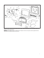
1
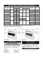
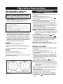
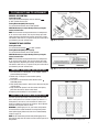
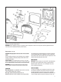
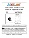
INSTALLER / CONSUMER
SAFETY INFORMATION
Please read this manual
before installing and using
the heater.
WARNING: If the information in
this manual is not followed
exactly, a fire or explosion may
result causing property damage,
personal injury or loss of life.
• Do not store or use gasoline or other
flammable vapors and liquids in the
vicinity of this or any other appliance.
•
Unvented
Gas-Fired Room Heater
Blue Flame Heaters
Models: RMC-LC10NG,
RMC-LC10LP
- 10,000 Btu/hr.
RMC-LC20NG(F),
RMC-LC20LP(F)
- 20,000 Btu/hr
RMC-LC30NG(F),
RMC-LC30LP(F)
- 30,000 Btu/hr
RMC-LC10NG(T),
RMC-LC10LP(T)
- 10,000 Btu/hr.
RMC-LC20NG(T),(F), RMC-LC20LP(T),(F) - 20,000 Btu/hr
RMC-LC30NG(T),(F), RMC-LC30LP(T),(F) - 30,000 Btu/hr
WHAT TO DO IF YOU SMELL GAS
Do not try to light any appliance.
Do not touch any electrical switch;
do not use any phone in your
building.
• Immediately call your gas supplier
from a neighbour’s phone. Follow the
gas supplier's instructions.
• If you cannot reach your gas
supplier, call the fire department.
• Installation and service must be
performed by a qualified installer,
service agency or the gas supplier.
•
•
Installer: Leave this manual
with the heater.
Consumer: Retain this
manual for future reference.
This is an unvented gas-fired
heater. It uses air (oxygen) from
the room in which it is installed.
Provisions for adequate
combustion and ventilation air
must be provided. Refer to the
Installation section on page 3.
(F)=Fan, (T)=Thermostat Gas Control
Infra-Red Heaters
Models: RMC-LI10NG,
RMC-LI18NG(F),
RMC-LI30NG(F),
RMC-LI06NG,
RMC-LI10NG(T),
RMC-LI18NG(T),(F),
RMC-LI30NG(T),(F),
RMC-LI10LP
RMC-LI18LP(F)
RMC-LI30LP(F)
RMC-LI06LP
RMC-LI10LP(T)
RMC-LI18LP(T),(F)
RMC-LI30LP(T),(F)
-
10,000
18,000
30,000
6,000
10,000
18,000
30,000
Btu/hr
Btu/hr
Btu/hr
Btu/hr.
Btu/hr
Btu/hr
Btu/hr
(F)=Fan, (T)=Thermostat Gas Control
User’s Operation and Installation Manual
07/05 Rev 3.
General Information
Table of Contents
Installer / Consumer Safety Information . . . .
General information . . . . . . . . . . . . . . . . . . .
Specifications . . . . . . . . . . . . . . . . . . . . . . . .
Installation . . . . . . . . . . . . . . . . . . . . . . . . . . .
Operating Instructions . . . . . . . . . . . . . . . . .
Troubleshooting . . . . . . . . . . . . . . . . . . . . .
Maintenance . . . . . . . . . . . . . . . . . . . . . . . .
Replacement Parts . . . . . . . . . . . . . . . . . . .
Accessories . . . . . . . . . . . . . . . . . . . . . . . .
Warranty . . . . . . . . . . . . . . . . . . . . . . . . . . .
1
2
3
4
8
10
11
12
14
16
SAFETY: Accidents are always tragic especially because so
many of them could have been prevented with a little care and
attention. These are some basic good practices we hope you
will follow for safe use of your gas fired room heater.
IMPORTANT: Read this user's manual carefully and
completely before trying to assemble, operate or service
this heater. Improper use of this heater can cause serious
injury or death from burns, fire, explosion, electrical shock
(fan models) or carbon monoxide poisoning.
Early signs of carbon monoxide poisoning resemble the flu
with headaches, dizziness or nausea. If you have these signs,
the heater may not be working properly. Get fresh air at once!
Have heater serviced. Some people are more affected by
carbon monoxide than others. These include pregnant
women, people with heart or lung disease or anemia, those
under the influence of alcohol or those at high altitude.
Begin by ensuring proper installation and servicing. Ensure
that your qualified technician who installs this heater follows
the installation instructions provided with this product. Have
the installer show you where the gas supply shut off valve is
located so that you know where to shut off the gas to the
heater. If the connections are not perfectly sealed or
tightened, you may have a leak and therefore a faint gas
smell. Finding a leak is NOT a do-it-yourself procedure.
Some leaks can only be found with the main burner gas on
and this must be done by a qualified technician.
This appliance may be installed in an aftermarket,
permanently located, manufactured (mobile) home, where not
prohibited by local codes. This appliance is only for use with the
type of gas indicated on the rating plate. This appliance is not
convertible for use with other gases. Any change to this heater or
its controls can be dangerous.
PRECAUTIONS
• Never use natural gas in a unit designed for propane gas.
• Never use propane in a unit designed for natural gas.
• Check all joints and connections. To avoid the
danger of fire, accident or explosion, never check a
potential gas leak with an open flame.
• An unvented room heater having an input rating of more than
10,000 BTU per hour shall not be installed in a bedroom or
2
bathroom and an unvented room heater having an input
rating of more than 6,000 BTU per hour shall not be installed
in a bathroom.
• Do not install RMC-LC30, LI30, LC20 or LI18 heaters in a
bedroom or a bathroom.
• Do not install RMC-LC10 or LI10 heaters in a bathroom, they
are allowed in bedrooms.
• LI06 heaters are allowed in bathrooms or bedrooms.
• This appliance is intended for supplemental heating.
• Do not use a blower or other accessory not approved for use
with this heater.
• Due to high temperatures, the appliance should be located
out of traffic and away from furniture and draperies. Keep
flammable objects more than 36” from the front and top of
the heaters and more than 10” from the sides of the heater
( 8” for the L106 heater).
• Provide adequate clearances for accessibility for purposes of
servicing the heater.
• Maintain adequate clearances around the air openings to
allow for proper and safe operation of the heater.
• WARNING: Do not allow fans to blow directly into the heater.
Avoid any drafts that alter the burner flame patterns.
SAFE OPERATION OF YOUR LEGACY
VENT FREE HEATER
• This heater needs fresh, outside air for combustion to run
properly. This heater has an oxygen depletion sensor (ODS)
pilot light safety system. The ODS shuts down the heater if
not enough fresh air (oxygen content > 18%) is available.
• Never run heater in confined space. Refer to page 4.
• If heater shuts off, do not relight until you provide fresh,
outside air. If heater keeps shutting off, clean it and have it
serviced.
• Keep appliance area clear and free from combustible
materials, gasoline and other flammable vapors and liquids.
• Keep burner and control compartment clean. See
maintenance section of this manual.
• Do not place clothing or other flammable material on or near
the appliance.
• Children and adults should be alerted to the hazard of high
surface temperatures and should stay away to avoid burns
and clothing ignition.
• Young children should be carefully supervised when they are
in the same room with the appliance. Never allow them to sit,
stand or play on or around the heater.
• Make sure that if the safety screen or guard is removed for
servicing or lighting the appliance, it is replaced prior to
operating the heater.
• Do not use the heater if any part has been under water.
Immediately call a qualified service technician to inspect the
room heater and to replace any part of the control system and
any gas control which has been under water.
• The ODS pilot light safety system is designed to prevent
asphyxiation due to a lack of oxygen in the air.
• The heater does not monitor the air for CO.
RMC-LCNG, RMC-LCLP, RMC-LING, RMC-LILP Specifications
Models
(Manual &
Thermostat)
RMC-LC30NG
Gas Type
Input Rating
(Btu/Hr) Variable
Regulator
Pressure
Setting
Inlet Gas Supply
Pressure
27”x24”x81/2”
30 lbs.
193/8”x227/8 ”x81/2”
22 lbs.
Max
30,000
10,000
20,000
RMC-LC10NG
5,000
10,000
151/2”x207/8 ”x77/8”
17 lbs.
RMC-LC30LP
15,000
30,000
27”x24”x81/2”
30 lbs.
10,000
20,000
RMC-LC10LP
5,000
RMC-LI30NG
Natural
LP
4.0” w.c.
5.0” w.c.
11” w.c.
11.0” w.c. 14.0” w.c. 193/8”x227/8 ”x81/2”
22 lbs.
10,000
151/2”x20 7/8 ”x77/8”
17 lbs.
6,400
30,000
27”x24”x81/2”
30 lbs.
6,400
18,000
193/8”x227/8 ”x81/2”
22 lbs.
5,500
10,000
151/2”x20 7/8 ”x77/8”
17 lbs.
RMC-LI06NG
-
6,000
151/2”x20 7/8 ”x77/8”
17 lbs.
RMC-LI30LP
6,400
30,000
27”x24”x81/2”
30 lbs.
6,400
18,00
193/8”x227/8 ”x81/2”
22 lbs.
5,500
10,000
151/2”x20 7/8 ”x77/8”
17 lbs.
-
6,000
151/2”x20 7/8 ”x77/8”
17 lbs.
RMC-LC20LP
RMC-LI18NG
Natural
RMC-LI10NG
RMC-LI18LP
LP
RMC-LI10LP
RMC-LI06LP
10” w.c.
Max
Weight
Min.
15,000
RMC-LC20NG
Min.
Size
of Heater
10” w.c.
11.0” w.c. 14.0” w.c.
NOTE: For altitude above 2,000 feet, reduce the input ratings (Btu/Hr) 4% for each 1,000 feet above sea level.
DO NOT USE THIS HEATER AT AN ELEVATION ABOVE 4,500 FEET
LOCAL CODES
PRODUCT FEATURES
RMC-LC30 / RMC-LC20 / RMC-LC10
RMC-LI30 / RMC-LI18 / RMC-LI10 / RMC-LI06
Certified to ANSI Z21.11.2b-2004 Unvented Heaters
SAFETY DEVICE
Install and use heater with care. Follow all local codes. In the
absence of local codes, use the latest edition of the National
Fuel Gas Code ANSI Z223.2, also known as NFPA54.
Available from:
American National
Standards Institute, Inc.
1430 Broadway
New York, NY 10018
National Fire Protection
Association, Inc.
Batterymarch Park
Quincy, MA 02269
This heater has a pilot with an Oxygen Depletion Sensor Shutoff system (ODS). The ODS pilot is a required feature for ventfree heaters. The ODS pilot shuts off the heater if the normal air
oxygen content is reduced below 18%.
PIEZO IGNITION SYSTEM
This heater has a piezo ignitor. This system requires no matches, batteries or other electrical sources to light the heater.
3
Installation
PROVIDE ADEQUATE COMBUSTION
AND VENTILATION AIR
• This heater shall not be installed in a confined space or
unusually tight construction unless provisions are provided
for adequate combustion and ventilation air.
• This heater must have fresh air for proper operation. If not,
poor fuel combustion could result. Read the following
instructions to insure proper fresh air for this and other fuel
burning appliances in your home.
Modern construction standards have resulted in homes that
are highly energy efficient and that allow little heat loss.
However, your home needs to breathe and all fuel burning
appliances need fresh air to function properly and safely.
Exhaust fans, clothes dryer, fireplaces and other fuel burning
appliances all use the air inside the building. If the available
fresh air supply is insufficient to meet the demands of these
appliances, problems can result.
Confined Space:
The National fuel Gas Code, ANSI Z223.1 / NFPA 54 defines a
confined space as a space whose volume is less than 50
cubic feet per 1000 BTU per hour (4.8 m3 per kw) of the
aggregate input rating of all appliances installed in that space.
Unconfined Space:
An unconfined space is defined in the same standards as a
space whose volume is not less than 50 cubic feet per 1000
BTU per hour (4.8 m3 per kw) of the aggregate input rating of
all appliances installed in that space. Rooms communicating
directly with the space in which the appliances are installed,
through openings not furnished with doors, are considered a
part of the unconfined space.
Example:
10,000 BTU Legacy heater should only be installed in a room
whose volume is more than 500 cubic feet. A room that is 8'
x 8' x 8' (512 cubic feet) would be acceptable for a Legacy
10,000 BTU/hour heater.
If an additional fuel fired appliance is installed in the same
room, the input rating of that appliance should be added to
that of the Legacy heater to determine the minimum sized
room that should be serviced by both appliances.
Unusually tight construction is defined as construction
where:
a) Walls and ceilings exposed to the outside atmosphere have a
continuous water vapour retarder with a rating of 1 perm (6 x
10-11 kg per pa-sec-m2) or less with openings gasketed or
sealed;
b) Weather stripping has been added on openable windows and
doors; and
c) Caulking or sealants are applied to areas such as joints
around window and door frames, between sole plates and
floors, between wall-ceiling joints, between wall panels, at
penetrations for plumbing, electrical and gas lines and at
other openings.
4
WARNING: If the area in which the heater may be operated is
smaller that that defined as an unconfined space or if the
building is of unusually tight construction, provide adequate
combustion and ventilation air by one of the methods
described in the National fuel Gas code, ANSI Z223.1 / NFPA
54, Section 5.3 or applicable local codes.
GAS TYPE
Verify the type of gas supply to be used, either natural gas or
LP (Propane), and make sure the marking on the appliance
rating plate agrees with that of the supply gas. The rating plate
is located on the side of the heater, which indicates the type of
gas the heater is manufactured for.
WARNING: This appliance is only for use with the type of gas
indicated on the rating plate.
This appliance is not convertible for use with other gases.
ITEMS NEEDED FOR
HEATER INSTALLATION
Before installing the heater, make sure you have these items:
• Gas piping (check local codes)
• Test gauge connection
• Sealant (resistant to LP gases) - approved thread
compound
• Manual shut-off valve*
• Sediment trap - where required
• Ground joint union
• Tee joint and pipe wrench
*An installer supplied design-certified manual shut-off valve
with 1/8 NPT tap connection.
LOCATING THE HEATER
• Due to high temperatures, the appliance should be located out
of traffic and away from furniture and draperies. Keep flammable objects more than 36” from the front and top of the
heaters and more than 10” from the sides of the heater.
• Provide adequate clearances for accessibility for purposes of
servicing the heater.
• Maintain adequate clearances around the air openings to
allow for proper and safe operation of the heater.
• WARNING: Do not allow fans to blow directly into the heater.
Avoid any drafts that alter the burner flame patterns.
This heater is designed to be mounted on a wall or on the floor.
WARNING: Never install the heater;
• in a bathroom*
• in a recreational vehicle
• where curtains, furniture, clothing or other flammable are
less than 36” from the front, top or sides of the heater
• as a fireplace insert
• in high traffic areas
• in windy or drafty areas
*Models RMC-L106NG or LP Permitted for bathroom installation.
WARNING: Vent-free heaters add moisture to the air. Although
this is beneficial, installing heater in rooms without enough
ventilation may cause mildew formation from too much
moisture content. See National Fuel Code for Fresh Air for
Combustion and Ventilation.
This appliance may be installed in an aftermarket, permanently
located manufactured (mobile) home, were not prohibited by
state or local codes.
Caution: If you install the heater in a home garage:
• Heater must be at least 18” above floor
• Locate heater where moving vehicle will not hit it.
• Install to ANSI Z223.2 / NFPA 54 using fixed gas supply piping.
Fig. 2 Minimum clearances from mounting holes to top surface of flooring,
adjacent walls and ceiling
ATTACH MOUNTING SCREWS TO WALL
NOTE: Wall anchors and mounting screws are in hardware
package provided with heater.
1. Install mounting screws on wall as shown in Figure 3. Use
enclosed paper template for proper location of holes. Be
sure template is level. It may be necessary to use plastic or
lead anchors for plaster walls.
2. Drill holes at marked location using 9/64” drill bit.
Insert mounting screws.
3. Leave screw head out from wall far enough to attach
heater.
PREPARING FOR INSTALLATION
1. Remove heater from carton
2. Remove all protective packaging applied to heater
for shipment.
3. Check heater for any shipping damage. If heater is
damaged, promptly inform dealer/distributor.
4. Select a location for the heater that will provide maximum
exposure of the radiant surface to the room, but will not be
subjected to accidental contact.
5. Adequate clearance must be available around the air opening. Refer to Figure 2 for clearances that must be maintained to the side walls, floor and horizontal surface surrounding the heater.
Fig. 3 Use paper template supplied to mark location of mounting holes.
Be sure template is level.
5
WALL ANCHOR METHOD
FLOOR INSTALLATION
When mounting heater to hollow walls (wall areas between
studs) or solid walls (concrete or masonry) it may be necessary to use wall anchors.
1. Place paper template on wall maintaining minimum clearance. Be sure template is level.
2. Drill holes at marked locations using 5/16”drill bit.
For solid walls, concrete or masonry, drill holes at least
1”deep.
3. Insert plastic anchor. Tap anchor flush to wall. (Fig. 4)
4. Insert screw into wall anchor leaving screw head out far
enough to attach heater. (Fig. 4)
5. Hang heater on mounting screws in holes provided at the
rear of the heater.
1. Heater may only be installed on a noncombustible flat
surface. Where the flooring is carpeting, tile or of other
combustible material other than wood flooring, maintain the
minimum clearances to the floor as shown in figure 2 or
else use a metal or wood panel (not supplied) extending the
full width and depth of the appliance.
2. Measure heater mounting screw location “X” as desired
above floor. (Fig. 5)
3. Use enclosed “paper template” for proper distance between
holes. Be sure template is level. It maybe necessary to use
plastic or lead anchors for plaster walls.
4. Leave screw head out from wall far enough to attach heater.
x = 173/4" 45 CM 30,000 BTU/hr units
161/2" 42 CM 18 & 20,000 BTU/hr units
141/4" 36 CM 6 & 10,000 BTU/hr units
Fig. 5 Optional wall mounting screws for floor installation.
Fig. 4 Wall anchor.
6
CONNECT TO GAS SUPPLY
Installation should be done by a qualified service person.
Before connecting the appliance, turn off all gas appliances.
Close the main gas valve at the gas meter or LP tank. Make
certain there is good ventilation where the installation will be
made. Installation should comply with all applicable building
codes and ANSI Z223.1, latest edition. Use PLP gas resistant
pipe compound to seal threaded joints.
An installer supplied, design certified gas pressure
regulator must be installed to bring the gas supply pressure
down to 14" w.c. for LP gas or 11" for natural gas.
PRESSURE TEST GAS SUPPLY
PIPING SYSTEM
The appliance and its individual shut off (control) valve must
be disconnected from the gas supply piping system during any
pressure testing of the system at test pressure in excess of
1/2 psi (3.5 kPa).
The appliance must be isolated from the gas supply piping
system by closing the individual manual shut-off valve (fig. 7)
during any pressure testing of the gas supply system at test
pressure equal to or less than 1/2 psi (3.5 kPa).
WARNING: Never connect an unregulated gas line to the
heater.
IMPORTANT: Check gas line pressure before connecting heater
to gas line. Gas line pressure must not be higher higher than
14" w.c. for LP gas or 11" for natural gas.
NOTE: The gas line connection can be made with 3/8”black or
steel pipe. Internally tinned copper tubing may be used in certain areas. Check your local codes. Use pipe of large enough
diameter to allow proper gas volume to heater. If pipe is too
small, undue pressure loss will occur.
CAUTION: Use pipe joint sealant that is resistant to liquefied
petroleum gases. Install sediment trap in supply as shown in
Figure 6.
Locate sediment trap where it is within reach for cleaning.
Locate sediment trap where matter is not likely to freeze. A
sediment trap prevents moisture and contaminant's from going
into the heater controls. If the sediment trap is not installed or is
installed wrong, the heater may not operate properly.
Test for gas leaks with a mild soap and water solution. Apply
water/soap solution with brush only - do not over apply.
NEVER test with an open flame.
Fig. 7 Manual shut-off valve location.
LEAK TESTING HEATER
GAS CONNECTION
1. Make sure control knob of heater is in the OFF position.
2. Open manual shut-off valve.
3. Open main gas valve located near gas meter.
4. check all joints from manual gas valve up to control valve
and including the manifold assembly. Apply the soap solution
around the connections, valve and tubing. Soap bubbles will
appear where a leak is present.
5. If a leak is present, immediately turn off gas supply, tighten
any leaky fittings, turn gas on and recheck.
6. To check burner and safety valve, the burner must be lit. (See
Operating Instructions) Check the rest of the connections for
leaks.
7. Turn off the heater prior to making any gas connection
repairs.
Fig. 6 Gas line connection
7
Operation Instructions
FOR YOUR SAFETY - READ THIS
SECTION BEFORE LIGHTING
WARNING: IF YOU DO NOT FOLLOW THESE INSTRUCTIONS
EXACTLY, A FIRE OR EXPLOSION MAY RESULT CAUSING
PROPERTY DAMAGE, PERSONAL INJURY OR LOSS OF LIFE
A. BEFORE LIGHTING smell all around the appliance area for
gas. Be sure to smell next to floor because some gas is
heavier than air and will settle on the floor.
IF YOU SMELL GAS:
1. Do not try to light appliance.
2. Do not touch electrical switches; do not use any phone in
your building.
3. Immediately call your gas supplier from a neighbour’s phone.
Follow your gas suppliers instructions.
4. If you cannot reach you gas supplier’s, call the fire department.
B. Use only your hand to push in or turn the gas valve control
knob. Never use tools. If the knob will not push in or turn by
hand, do not try to repair it, call a qualified service technician.
Force or attempted repair may result in a fire or explosion.
C. Do not use this appliance if any part has been under water.
Immediately call a qualified service technician to inspect the
appliance and to replace any part of this control system and
any gas control which has been under water.
ATTENTION:
Keep burner and control compartment clean.
See installation and operating instructions accompanying the
heater.
See the safety information on the sides of the heater.
WARNINGS:
Hot while in operation. Do not touch.
Keep children, clothing and furniture away.
Do not light or operate where gasoline and other liquids having
flammable vapors are present.
RMC-LC10, RMC-LI10 & LI06 Only
Fig. 8 Control knobs
8
LIGHTING INSTRUCTIONS
MANUAL GAS CONTROL
1. Stop! Read and Heed the Warnings and Cautions on the side
of the heater.
2. Check that gas supply to the heater is on.
3. Push in gas control knob slightly and turn clockwise
to “OFF” position.
NOTE: knob cannot be turned from "PILOT" to "OFF" unless
knob is pushed in slightly. Do not force.
4. Wait five (5) minutes to clean out any air. Then smell for gas,
including near the floor. If you smell gas, STOP! Follow "B" in
the safety information on the side of the heater. If you do not
smell gas, go to the next step.
5. Push in gas control knob slightly and turn counterclockwise
to "PILOT/IGN” and depress for five (5) seconds.
NOTE: The first time that the heater is operated after connecting
the gas supply, the control knob should be depressed for
about thirty (30) seconds. This will allow air to bleed from
the gas system.
6. Release control knob and turn clockwise
to "OFF".
7. Depress control knob while "OFF", then turn back to
to "PILOT/IGN”. This should cause the spark from the piezo
ignitor to light the pilot gas. Keep control knob depressed for
ten (10) seconds before releasing. If pilot does not light,
repeat steps 5, 6 and 7 or use a match.
8. When pilot is lit, turn the ignition knob to "ON".
9. To select the heating level desired, use the knob LOW to HIGH.
THERMOSTAT GAS CONTROL
1. Stop! Read and Heed the Warnings and Cautions on the side
of the heater.
2. Check that gas supply to the heater is on.
3. Push in gas control knob slightly and turn clockwise
to “OFF” position.
4. Wait five (5) minutes to clean out any air. Then smell for gas,
including near the floor. If you smell gas, STOP! Follow "B" in
the safety information on the side of the heater. If you do not
smell gas, go to the next step.
5. Turn control knob counterclockwise
to “PILOT”
position. Press in control knob for five (5) seconds.
NOTE: The first time that the heater is operatedafter connecting
the gas supply, the control knob should be depressed for
about thirty (30) seconds. This will allow air to bleed from
the gas system.
6. With control knob pressed in, push down and release ignitor
button. This will light pilot. If needed, keep pressing ignitor
button until pilot lights.
7. Keep control knob pressed in for 30 seconds after lighting
pilot. After 30 seconds, release control knob.
8. If pilot goes out, repeat steps 5 through 7 or use a match.
9. When pilot is lit, turn control knob to on.Turn control knob
counterclockwise
to desired heating level between
5 and 1.
TO TURN OFF GAS TO APPLIANCE
MANUAL GAS CONTROL
Turning Heater Off
Push in gas control knob slightly and turn clockwise
to "OFF" position. Do not force.
Turning Burner Only Off (Pilot stays lit).
Turn control knob clockwise to the PILOT position.
CAUTION: Do not try to adjust heating levels by using the
manual shut-off valve.
NOTE: The thermostat sensing bulb measures the temperature
of air near the heater cabinet. This may not always agree with
room temperature (depending on housing construction, installation location, room size, ect.). Frequent use of your heater will let
you determine your own comfort levels.
Fig. 9 Proper pilot flame
THERMOSTAT GAS CONTROL
Turning Heater Off
Turn control knob clockwise
to “OFF” position.
Turning Burner Only Off (Pilot stays lit).
Turn control knob clockwise to the PILOT position.
CAUTION: Do not try to adjust heating levels by using the
manual shut-off valve.
NOTE: The thermostat sensing bulb measures the temperature
of air near the heater cabinet. This may not always agree with
room temperature (depending on housing construction, installation location, room size, ect.). Frequent use of your heater will let
you determine your own comfort levels.
MANUAL LIGHTING INSTRUCTION
Fig. 10 Correct burner flame pattern for the RMC-LC blue flame burner.
1. Use a long match or a BBQ lighter. If not available, remove
guard assembly by flexing it.
2. Follow steps 1 through 4 as stated under Lighting
Instructions.
3. Press and turn control knob counterclockwise to the
PILOT/IGN position
4. With control knob pressed in, strike match, hold match to pilot
until pilot lights.
5. Keep control knob pressed in for 30 seconds after lighting
pilot. After 30 seconds, release control knob.
6. Replace guard assembly if it was removed in step 1.
PILOT AND BURNING INSPECTION
Each time you light your heater check that the pilot flame and
burner flame patterns are as shown in Figures 9, 10 and 11. If
flame patterns are incorrect, turn the heater off. Contact your
dealer or qualified gas technician for assistance. Do not operate
the heater until the pilot flame is correct.
WARNING: If yellow tipping occurs, your heater could produce
increased levels of carbon monoxide. If burning flame pattern
shows yellow tipping, follow instruction in the Troubleshooting
section on page 10.
NOTE: Do not mistake orange flames with yellow tipping. Dirt or
other particles may enter the heater and cause transient patches of
orange flame.
Fig. 11 Correct burner flame pattern for the RMC-LC plaque heater.
9
Troubleshooting
Problem
When control knob is pressed in
and turned counterclockwise to
ignition, there is no spark at
ODS pilot.
Possible Cause
1. Ignitor electrode positioned wrong.
2. Ignitor electrode broken.
3. Ignitor cable pinched or broken.
4. Ignitor cable not connected to ignitor
electrode.
What To Do
1. Reposition ignitor electrode.
2. Replace electrode.
3. Free ignitor cable, if damaged, replace.
4. Connect cable to electrode
When control knob is pressed in 1. Gas supply turned off.
and turned counterclockwise to 2. Control knob not in pilot position.
ignition/pilot position there is
3. Control knob not pressed in while in pilot
spark but no ignition
position.
4. ODS pilot is clogged.
5. Air in gas lines.
1. Turn gas supply on.
2. Turn control knob to pilot position.
3. Press in control while in pilot position.
4. Call a qualified service technician.
ODS pilot lights but flame
goes out when control knob
is released.
1.Control knob not pressed long enough.
2. Safety interlock is triggered.
3. Pilot flame not touching the thermocouple.
Problem could be result of one or both of
the following:
• Partially clogged ODS pilot orifice.
• Low gas pressure.
4. Thermocouple damaged.
5. Thermocouple connection loose at gas
control valve.
6. Gas control valve damaged.
1. After ODS pilot lights, keep control knob
pressed in approximately 30 seconds.
2. Wait one minute, repeat ignition operation.
3. Contact your gas company, gas supplier or
qualified service technician.
Burner does not light after ODS
pilot is lit.
1. Burner orifice clogged.
2. Gas supply pressure is very low.
1. Clean burner orifice.
2. Contact gas supplier.
Delayed ignition.
1. Main burner carry over ports clogged.
2. Gas supply pressure is very low.
1. Clean main burner ports.
2. Contact gas supplier.
Burner backfiring during
operation.
1. Burner orifice is clogged.
2. Burner ports damaged.
1. Clean burner orifice.
2. Replace burner.
Yellow flames during burner
operation. (RMC-LC)
1. Not enough air
1. Check air passageways and burner for dirt and
debris (Refer to Maintenance section)
Burner plaque(s) does not glow.
(RMC-LI)
1. Plaque(s) is damaged.
1. Replace burner.
2. Inlet gas pressure too low.
2. Contact local gas supplier.
3. Control knob set between locked positions. 3. Turn control knob until it locks at desired
setting.
Slight smoke and odor during
initial operation.
1. Residues from manufacturing processes.
1. Will stop after a few hours of operation.
Heater produces a whistling
noise when burner is lit.
1. Air passageways blocked.
1. Check minimum installation clearances and air
passageways for debris.
2. Operate burner until the air is completely
purged.
2. Air in gas line.
10
5. Purge gas lines and repeat ignition operation.
4. Replace thermocouple.
5. Hand tight until snug then tighten 1/4 turn with
a wrench.
6. Replace gas control.
Troubleshooting continued
Problem
Possible Cause
What To Do
Heater produces a clicking
noise just after burner is lit or
turned off.
1. Metal expanding and contracting.
1. This is common with heaters. If noise is
excessive, contact a qualified service
technician.
Gas odor even when control
knob is in OFF position.
1. Gas leaks. Refer to front of page Warnings. 1. Locate and correct leaks immediately.
2. Gas control defective.
2. Replace gas control.
Gas odor during combustion.
1. Foreign matter in gas or on burner ports.
2. Heater burning vapors form paint,
impurities in air.
3. Gas leaks, refer to front page Warnings.
1. Check gas passage way and burner.
2. Ventilate room, stop storing and using odor
causing products near heater.
3. Locate and correct leaks immediately.
Heater shuts off on ODS.
1. Not enough fresh air is available.
2. Low gas pressure.
3. ODS pilot partially clogged.
1. Open window.
2. Contact gas supplier.
3. Clean the pilot.
Maintenance
Repair should be done by a qualified service person.
The appliance should be inspected before use and at least
annually by a professional service person. More frequent
cleaning may be required due to excessive lint from carpeting,
bedding material, etc. It is imperative that control
compartments, burners and circulating air passageways of the
heater be kept clean. Dust, lint, cobwebs or debris may affect
heater performance. The heater draws air into it during normal
operation and in the process dust, lint or debris may be drawn
in also. It is important to keep the burner, gas control and
combustion and circulating air passageways clean. Inspect or
have these areas inspected annually at the beginning of the
heating season by a qualified service person. Depending on
the surroundings, the room heater may require frequent cleaning due to excessive lint or debris.
Before cleaning ensure the gas supply is off and the gas control knob is in the OFF position. Make sure the heater is cool.
WARNING: Danger of bodily injury. If fan assembly accessory is used, turn off power supply at disconnect switch or
service panel before removing any access panels from
heater.
BURNER AND ODS PILOT CLEANING
Clean the exterior with soft bristle brush, vacuum cleaner or
pressurized air. Never use a wooden toothpick as it may break
off and clog the ODS pilot or main burner port.
Use a flashlight to inspect the main burner inlet to ensure it is
not blocked. If obstruction can be seen, use a metal wire coat
hanger that has been straightened out. Use a vacuum cleaner
to clean the primary air openings to the main burner(s).
WARNING: Failure to keep the primary air openings to the
burner(s) clean may result in sooting and property damage.
In order to clean ODS pilot orifice, use pressurized air to blow
dust out. Sometimes blowing air backwards through the pilot
will get rid of the accumulated dirt. If that does not work blow
out any dust through primary air openings of pilot assemblies
(This unit has two openings; one beneath the bimetal strip and
the second one opposite from bimetal strip. Use the one wide
open, do not try to lift the bimetal strip.)
CLEANING AIR PASSAGEWAYS AND
UNIT CASINGS
Use a vacuum cleaner or pressurized air to clean the combustion and circulating air passageways and dampened cloth to
clean the cabinet/casing.
11
RMC-LI NG/LP Unvented Room Heater
Item/Model Number
RMC-LI06NG/LP
RMC-LI10NG(T)/LP(T) RMC-LI18NG(T)/LP(T) RMC-LI30NG(T)/LP(T)
1.
Lower Heat Cover
LI10LP-01-01-02
LI10LP-01-01-02
LI18LPT-01-01-03
LI30NG-01-01-02
2.
Guard Assembly
LC10NG-01-04
LC10NG-01-04
LI18LPT-01-04
LC30NGTF-01-04
3.
Reflector
LI10LP-01-01-01
LI10LP-01-01-01
LI18LPT-01-01-01
LI30NG-01-01-01
4.
Upper Heat Cover
LC10NG-01-01-02
LC10NG-01-01-02
LI18LPT-01-01-02
LC30NGTF-01-01-02
5.
Leg Front
LC10NG-05
LC10NG-05
LC10NG-05
LC10NG-05
6.
Front Panel
LC10NG-01-03
LC10NG-01-03
LI18LPT-01-03
LC30NGTF-01-03
7.
Burner Assembly Body
LI6LP-03-00
LI10LP-03-00
LI18LPT-03-00
LI30LPTF-03-00
8.
Ceramic Plate
LI18LPT-03-09
LI10LP-03-03
LI18LPT-03-09
LI18LPT-03-09
9.
Body Frame Assembly
LC10NG-02-00
LC10NG-02-00
LC20NG-02-00
LC30LP-02-00
10.
Knob – Valve
LC10NG-12-00
LC10NG-12-00
LC10NG-12-00
LC10NG-12-00
11.
Leg – Rear
LC10NG-04
LC10NG-04
LC10NG-04
LC10NG-04
12.
Valve Link
LI6LP-02
LI6LP-02
LI18LPF-02
LI30NG-02
13.
Fix Pin – Link
LI6LP-03
LI6LP-03
LI6LP-03
LI6LP-03
14a.
Gas Control
CK-890SL-A1/00(B)
CK-890SL-A1/00(D)
CK-890SL-A1/00(E)
CK-890SL-A1/00(E)
14b.
Thermostat Gas Control
LI18LPT-04-00
LI18LPT-04-00
LI18LPT-04-00
15.
Tubing Inlet Assembly
LI10LP-07-00
LI18LPF-07-01
LI30NG-07-01
16a.
Outlet Tubing Assembly
LI10NGT-08-00
LI18LPT-08-00
LI30LPTF-08-00
16b.
Tubing Outlet – A Assembly
LI10LP-08-00
LI18LPF-08-00
LI30NG-08-00
17.
Tubing Outlet – B Assembly
LI10LP-10-00
LI18LPF-10-00
LI30NG-10-01-00
18.
Tubing Outlet – BL Assembly
19.
Tubing Outlet – BR Assembly
20.
Tubing Outlet – C Assembly
21.
Tubing Outlet – CL Assembly
LI30NG-11-02-00
22.
Tubing Outlet – CR Assembly
LI30NG-11-03-00
23a.
Manifold – “C”
23b.
Manifold Assembly
-
LI10NGT-03-02-00
LI18LPT-03-02-00
LI30LPTF-03-02-00
24.
ODS Tubing Assembly
LI6LP-09-00
LI10LP-09-00
LI18LPF-09-00
LI30NG-09-00
25a.
ODS Pilot Assembly – Natural
144NG 4-7"
NG 8224
NG 8224
NG 8224
25b.
ODS Pilot Assembly – LP
158LP 8-11"
LPG 8420
LPG 8420
LPG 8420
26a.
Main Nozzle – Natural
LI6NG-08-05
LI10NG-08-05
LI6NG-08-05
LI6NG-08-05
26b.
Main Nozzle – LP
LI6LP-08-05
LI10LP-08-05
LI06LP-08-05
LI06LP-08-05
27.
Connector – “B”
LC10NG-05-02
LC10NG-05-02
LC10NG-05-02
LC10NG-05-02
28a.
Pressure Regulator – Natural
RTZ-11/20B3
RTZ-11/20B1
RTZ-11/20B3
RTZ-11/20B3
28b.
Pressure Regulator – LP
RTZ-11/20B4
RTZ-11/20B2
RTZ-11/20B4
RTZ-11/20B4
29.
Rear Radiant Heat Shield
LC10NG-01
LC10NG-01
-
LC30NGTF-01
30.
Shield
-
-
LI18LPT-01
-
31.
Optional Fan-Natural/LP
-
-
RMA-FT
RMA-FT
12
LI6LP-07-00
LI6LP-08-00
LI30NG-10-02-00
LI30NG-10-03-00
LI18LPF-11-00
LI30NG-11-01-00
LI30NG-10-02
CFM Home Products reserves the right to make changes in design, materials, specifications, prices and discontinue colors and
products at any time, without notice.
WARNING: Failure to position the parts in accordance with this diagram or failure to use only parts specifically approved with this
heater may result in property damage or personal injury.
13
RMC-LC NG/LP Unvented Room Heater
Item/Model Number
RMC-LC10NG/LP
RMC-LC20NG/LP
RMC-LC30NG/LP
1.
2.
3.
4.
5.
6a.
6b.
7.
8a.
8b.
Guard Assembly
Glass Panel
Glass Holder
Reflector
Heat Cover – Upper
Pressure Regulator – Natural
Pressure Regulator – LP
Nozzle Holder
ODS Pilot Assembly – Natural
ODS Pilot Assembly – LP
LC10NG-01-04
LC10NG-01-02-01
LC10NG-01-02-02
LC10NG-01-01-01
LC10NG-01-01-02
RTZ-11/20B5
RTZ-11/20B2
LC10NG-03-13
NG 8224
LPG 8420
LI18LPT-01-04
LC20NGT-01-02-01
LC10NG-01-02-02
LC20NGT-01-01-01
LI18LPT-01-01-02
RTZ-11/20B1
RTZ-11/20B2
LC10NG-03-13
NG 8224
LPG 8420
LC30NGTF-01-04
LC30NGTF-01-02-01
LC10NG-01-02-02
LC30NGTF-01-01-01
LC30NGTF-01-01-02
RTZ-11/20B1
RTZ-11/20B2
LC10NG-03-13
NG 8224
LPG 8420
9.
Fix Nut – Nozzle Holder
LC10NG-03-11
LC10NG-03-11
LC10NG-03-11
10a.
10b.
11a.
11b.
12a.
12b.
12c.
12d.
Main Nozzle – Natural
Main Nozzle – LP
Valve Bracket-Manual Gas Control
Valve Bracket-Thermostat Gas Control
Manual Gas Control-Natural
Manual Gas Control-LP
Thermostat Gas Control-Natural
Thermostat Gas Control-LP
LC10NG-03-12
LC10LP-03-12
LC10NG-04-02
LI18LPT-04-02
CK-890SL-A1/00(C)
CK-890SL-A1/00(C)
LC10NGT-04-00
LC10NGT-04-00
LC20NG-03-12
LC20LP-03-12
LC10NG-04-02
LI18LPT-04-02
CK-890SL-A1/00(F)
CK-890SL-A1/00(F)
LC20NGT-04-00
LC20NGT-04-00
LC30NGTF-03-12
LC30LP-03-12
LC10NG-04-02
LI18LPT-04-02
CK-890SL-A1/00(F)
CK-890SL-A1/00(F)
LC30NGTF-04-00
LC30NGTF-04-00
13.
14.
15.
16.
17.
18.
19a.
19b.
20.
21.
22.
23.
24.
25.
Outlet Tubing Assembly
ODS Tubing Assembly
Inlet Tubing Assembly
Leg – Front
Front Panel
Burner Assembly
Burner Support – Left
Burner Support – Right
Body Frame Assembly
Leg – Rear
Knob – Valve
Shield
Rear Radiant Shield
Optional Fan-Natural/LP
LC10NG-08-00
LC10NG-09-00
LC10NG-07-00
LC10NG-05
LC10NG-01-03
LC10NG-03-00
LC10NG-03-08
LC10NG-03-09
LC10NG-02-00
LC10NG-04
LC10NG-12-00
LC10NG-01
-
LC20NG-08-00
LC20NG-09-00
LC20NG-07-00
LC10NG-05
LI18LPT-01-03
LC20NGT-03-00
LC10NG-03-08
LC10NG-03-09
LC20NG-02-00
LC10NG-04
LC10NG-12-00
LI18LPT-01
LC30LP-08-00
LC30LP-09-00
LC30LP-07-00
LC10NG-05
LC30NGTF-01-03
LC30NGTF-03-00
LC10NG-03-08
LC10NG-03-09
LC30LP-02-00
LC10NG-04
LC10NG-12-00
LC30NGTF-01
RMA-FT
RMA-FT
The following accessories are available from your local distributors/dealer. Each accessory comes with a separate installation
instruction. Be sure to read each instruction thoroughly before installation.
Accessories
OPERATION & MAINTENANCE INSTRUCTIONS
FMA-(F,FT) MANUALLY & THERMOSTATICALLY CONTROLLED
BLOWERS
Description
Model Number
Manual Fan Kit
Thermostat Fan Kit
FMA-F
FMA-FT
IMPORTANT: The blower power cord is equipped with a three
prong grounding plug for your safety and protection against
electric shock. Do not modify the plug provided if it will not fit the
outlet source. Have the proper source outlet installed near the
heater location to avoid damage to the power cord. Source outlet
and grounding plug are illustrated in the Fig. 12.
Fig. 12
14
CFM Home Products reserves the right to make changes in design, materials, specifications, prices and discontinue colors and
products at any time, without notice.
WARNING: Failure to position the parts in accordance with this diagram or failure to use only parts specifically approved with this
heater may result in property damage or personal injury.
Accessories continued
CAUTION: Damaged power cord can cause a fire or electric
shock.
Prior to installing the blower, check for blower for any shipping
damage. If blower is damaged, promptly inform dealer where
you bought the blower.
INSTALLATION: Plug the blower power cord into a 110-120V
properly grounded type outlet (three prong receptacle) protected
by a 15 amp time delay or Circuit Saver fuse for circuit breaker.
for thermostatically controlled operation as desired. Thermostat
turns the blower ON when the temperature near the discharge
area reaches 105F and turns it OFF when the temperature at the
aforementioned location goes down to 86F.
MAINTENANCE:
WARNING: Do not let your fingers touch the prongs of plug
when installing or removing the plug from the power outlet.
WARNING: For your safety, turn switch “OFF” and remove plug
from power source outlet before cleaning and maintaining
blower. If power cord is worn, cut, or damaged in any way,
have it replaced immediately.
OPERATION:
CARE OF BLOWER
Manually Operated: Use the ON/OFF rocker switch to manually
switch the blower ON or OFF as desired.
In normal use, blower may accumulate excessive lint or dust,
so the blower should be vacuumed or brushed and checked
for proper operation at least once each year by a qualified
service personnel. Excessive accumulation of lint and dust can
cause the blower motor to overheat frequently and burn out.
Manually & Thermostatically Controlled: Use the
MAN/OFF/AUTO rocker switch to MAN for manual ON or AUTO
15
WARRANTY
Service and Limited Warranty
CFM Home Products warrants this product to be free from
defects in materials and components for three (3) years from
the date of first purchase, provided that the product has been
properly installed, operated and maintained in accordance
with all applicable instructions. To make a claim under this
warranty the Bill of Sale or cancelled check must be presented. This warranty is extended only to the original retail purchaser. This warranty covers the cost of part(s) required to
restore this heater to proper operating condition and labor
when provided by a CFM Home Products Authorized Service
Center.
Warranty part(s) MUST be obtained through authorized dealers
of this product and/or CFM Home Products who will provide
original factory replacement parts. Failure to use original factory replacement parts voids this warranty. The heater MUST
be installed by a qualified installer in accordance with all local
codes and instructions furnished with the unit.
This warranty does not apply to parts that are not in original
condition because of normal wear and tear, or parts that fail or
become damaged as a result of misuse, accidents, lack of
proper maintenance or defects caused by improper installation. Travel, diagnostic cost, labor, transportation and any and
all such other costs related to repairing defective heater will
be the responsibility of the owner.
Contact CFM Home Products with questions concerning prices
and policies covering replacement parts. Parts may be ordered
through CFM Home Products distributor or dealer. You will
need the following information when ordering replacement
parts:
• The
appliance model number.
• The
serial number.
•A
description of the part.
Should you need additional information beyond
what your dealer can furnish, contact:
DISTRIBUTOR:
CFM Home Products
2695 Meadowvale Boulevard
Mississauga, Ontario, L5N 8A3
CANADA
Telephone: 1-800-668-5323
TO THE FULL EXTENT ALLOWED BY THE LAW OF THE JURISDICTION THAT GOVERNS THE SALE OF THE PRODUCT; THIS
EXPRESS WARRANTY EXCLUDES ANY AND ALL OTHER
EXPRESSED WARRANTIES AND LIMITS THE DURATION OF ANY
AND ALL IMPLIED WARRANTIES, INCLUDING WARRANTIES OF
MERCHANTABILITY AND FITNESS FOR A PARTICULAR PURPOSE TO THREE (3) YEARS FROM THE DATE OF FIRST PURCHASE; AND CFM HOME PRODUCTS' LIABILITY IS HEREBY
LIMITED TO THE PURCHASE PRICE OF THE PRODUCT AND CFM
HOME PRODUCTS SHALL NOT BE LIABLE FOR ANY OTHER
DAMAGES WHATSOEVER INCLUDING INDIRECT, INCIDENTAL OR
CONSEQUENTIAL DAMAGES.
Some states do not allow a limitation on how long an implied
warranty lasts or an exclusion or limitation of incidental or
consequential damages, so the above limitation on implied
warranties, or exclusion or limitation on damages may not
apply to you.
This warranty gives you specific legal rights, and you may also
have other rights that vary from state to state. Always specify
model and serial number when communicating with the
factory.
Model and serial numbers are listed on the rating plate
(located on right side of heater).
Record your model and serial number here for future
reference.
Model #
Serial #