1
ST IG A VILL A
85 M
8211-3013-10
A
1.
5.
B
2.
6.
3.
7.
4.
8.
2
10.
9.
Z
X
V
Y
W
11.
Denna produkt, eller delar därav, omfattas av följande
mönsterskydd:
This product, or part of it, is covered by the following
design registration:
Sverige/Sweden
62 435
3
GB
ENGLISH
SYMBOLS
The following symbols are displayed on the machine in order to remind you about the safety precautions and attention necessary when using the
machine.
The symbols mean:
Warning!
Read the instruction book and safety manual before using the machine.
ASSEMBLY
MOWER DECK
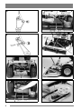
1. Remove both mounting bolts D on the base machine (fig 3).
2. Insert both spacer sleeves E in the mower deck's
arms (fig 4). The spacer sleeves are supplied in a
plastic bag.
3. Bolt the mower deck to the base machine.
Warning!
Do not put hands or feet under the cover of
the machine when it is running.
Warning!
Beware of objects being flung out. Keep
spectators away.
Warning!
Before starting any repair work, remove the
spark plug cable from the spark plug.
4. Pull the v-belt onto the mower deck's pulley.
(This is carried out easier if the height adjustment
lever is in position "5").
5. Make sure that the tension roller J is on the outside of the v-belt (figs 2 and 5).
6. Hook the spring into the bracket G (figs 2 and 5).
7. Screw the guard H in position using three screws
(fig 6). The screws are supplied in the plastic bag.
8. Hook the chain I and lifting spring F in the attachment's lift arm (fig 6).
SETTING
INTRODUCTION
For the mower deck to mow evenly and cleanly it
needs to be adjusted correctly:
The power outlet's tension roller and tension arm's
spring on the base machine are available in two versions (figs 1 and 2).
1. Make sure the tyre pressure is correct:
Front: 0.4 bar (6 psi).
Rear: 1.2 bar (17 psi).
NOTE! To be able to fit this mower deck ("Multiclip" mod. 85M) version B is required.
2. Place the machine on a flat surface. Loosen the
screws K (fig 7).
VERSION A:
(Standard on models made between 1982 - 83).
3. Adjust the mower deck so that the casing's front
and rear edges are the same height from the floor.
If the base machine is fitted with version A a separate assembly set is required to be able to fit the
mower deck.
4. Tighten the screws.
Assembly set, art. No.: 13-1967-11.
The set contains a v-belt, tension roller, spring, assembly components and assembly instructions.
N.B. Older base machines can, however, be fitted
with version B if they have previously been adapted
for use with a "Multiclip" mower deck.
VERSION B:
(Standard on machines made from 1994 - ).
The mower deck can be fitted directly.
USE
MOWING HEIGHT
The mower deck has 17 fixed mowing heights, from
30 mm to 80 mm.
N.B. The stated mowing heights apply when the
machine is standing on firm ground.
MOWING ADVICE
For the best "Multiclip" effect follow this advice:
- mow regularly.
- use full throttle on the engine.
5
GB
-
ENGLISH
keep the underside of the mower deck clean.
use sharp blades.
do not mow wet grass.
mow twice (using different mowing heights)
if the grass is long.
MAINTENANCE
No service action must be taken on the
mower deck unless:
- the engine has been stopped.
- the ignition key has been removed.
- the spark plug cap has been removed
from the spark plug.
- the parking brake is engaged.
- the mower deck is disengaged.
CLEANING
After use, rinse off the underside of the mower
deck using a garden hose.
If grass cuttings have dried on to the attachment,
dismantle the mower deck and scrape clean the underside.
If necessary touch-up the underside using a suitable paint to prevent corrosion.
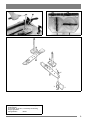
CHANGING THE DRIVE BELT
1. Remove the mower deck from the base machine.
2. Remove the transmission casing.
chine.
8. Now refit the mower deck on the base machine.
CHANGING BLADES
Use protective gloves to prevent cuts
when changing blades/blade tips.
Make sure the blades are always sharp. This gives
the best mowing results.
Always check the blade(s) after an impact. If the
blade system has been damaged the defective parts
must be changed.
Always use original spare parts. Using
non-original spare parts can result in
the risk of damage even if they fit in the
machine.
The cutting system consists of two blade bars, each
with two interchangeable blade tips Y (fig 11).
Both blade tips should be replaced at the same time
to avoid any imbalance.
Fit the new blade tips. Tighten the screws V and W
fully. Tightening torque: V - 9.8 Nm, W - 24 Nm.
And heavy impact can result in the blade tip being
folded aside. Loosen the locking nut X and turn the
blade tip back to its correct position. Mount a new
shear bolt V. Tighten the lock nuts X and Z.
SPARE PARTS
3. Loosen the tension arm L (fig 8).
4. Loosen the right hand bearing box's fixing bolts
M (fig 9).
5. Fit the new drive belt.
The new drive belt must be fitted so that
the blades are square (90°) to each other. See figure 10. If you fit the drive belt
incorrectly the blades will hit each other resulting in the blades being damaged.
STIGA original spare parts and accessories are
constructed exclusively for STIGA machines.
Note that non original spare parts and accessories
have not been checked or approved by STIGA.
Usage of such parts and accessories can
influence the machines operability and
safety. STIGA cannot be held responsible for injuries caused by these products.
6. The belt is tensioned by pushing the tension arm
L forwards and then securing in position.
7. Tighten the bearing box's fixing bolts M.
When the drive belt is fitted, check, by
turning the mower deck over and turning the blades, that it has been fitted
correctly. NOTE! The mower deck
should be dismantled from the base ma6
STIGA reserves the right to make changes in the product without prior notice.