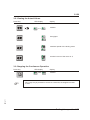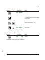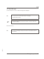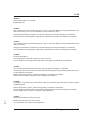
1
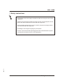
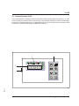
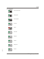
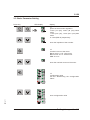
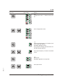
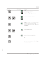
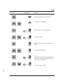
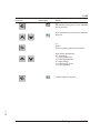
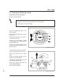
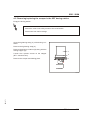
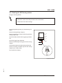
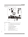
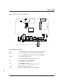
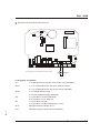
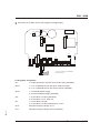
Operating Instructions
SM1-671
SDD 1 SGM
with S 150 control unit
Sterling Material Processing
SDD 1 SGM
Sterling Material Processing
5200 West Clinton Ave.
Milwaukee, WI 53223
Telephone (414) 354-0970
Fax: (414) 354-6421
www.sterlco.com
Parts & Service department:
Telephone: (800) 423-3183
Edition: 07/01
This operation manual is for*:
(* Please fill in personally)
Serial number:
Built in:
Date of delivery:
Number of delivery:
Date of commissioning:
SM1-671
Location:
Group of machines:
2
SDD 1 SGM
Sterling Material Processing retains all rights to change the information in these
operating instructions at any time without notice.
SM1-671
We assume no liability for any errors or direct or indirect damage resulting in context with these operating instructions.
Copying, translation or publication in any form except for personal use of purchaser requires approval from Sterling Material Processing.
All rights reserved.
3
SDD 1 SGM
Table of contents
1. Safety instructions . . . . . . . . . . . . . . . . . . . . . . . . . . . . . . . . . . . . . . . . . . . . . . . . . . . . . . . . 1-1
1.1. For your safety . . . . . . . . . . . . . . . . . . . . . . . . . . . . . . . . . . . . . . . . . . . . . . . . . . . 1-2
1.2. For the operating safety of the equipment . . . . . . . . . . . . . . . . . . . . . . . . . . . . . 1-4
2. Concerning these Operating Instructions . . . . . . . . . . . . . . . . . . . . . . . . . . . . . . . . . . . . 2-1
2.1. Warning Messages and Symbols . . . . . . . . . . . . . . . . . . . . . . . . . . . . . . . . . . . . 2-2
2.2. Explanations and Definitions . . . . . . . . . . . . . . . . . . . . . . . . . . . . . . . . . . . . . . . . 2-3
2.3. Notes on Usage . . . . . . . . . . . . . . . . . . . . . . . . . . . . . . . . . . . . . . . . . . . . . . . . . . 2-3
3. Putting into operation. . . . . . . . . . . . . . . . . . . . . . . . . . . . . . . . . . . . . . . . . . . . . . . . . . . . . . 3-1
3.1. Control System S 150 . . . . . . . . . . . . . . . . . . . . . . . . . . . . . . . . . . . . . . . . . . . . . 3-2
3.1.1. Key Assignment . . . . . . . . . . . . . . . . . . . . . . . . . . . . . . . . . . . . . . . . . 3-3
3.1.2. Symbols . . . . . . . . . . . . . . . . . . . . . . . . . . . . . . . . . . . . . . . . . . . . . . . 3-4
3.2. Initial operation procedure . . . . . . . . . . . . . . . . . . . . . . . . . . . . . . . . . . . . . . . . . . 3-5
3.3. Basic Parameter Setting . . . . . . . . . . . . . . . . . . . . . . . . . . . . . . . . . . . . . . . . . . . 3-9
3.4. Calibration . . . . . . . . . . . . . . . . . . . . . . . . . . . . . . . . . . . . . . . . . . . . . . . . . . . . . . 3-12
3.4.1. Preparations . . . . . . . . . . . . . . . . . . . . . . . . . . . . . . . . . . . . . . . . . . . 3-12
3.4.2. Determining the Calibration Weight . . . . . . . . . . . . . . . . . . . . . . . . 3-14
3.4.3. Preparing the Feed Station for Normal Operation. . . . . . . . . . . . . 3-16
3.5. Modify/Create Recipe. . . . . . . . . . . . . . . . . . . . . . . . . . . . . . . . . . . . . . . . . . . . . 3-17
3.5.1. Save Recipe . . . . . . . . . . . . . . . . . . . . . . . . . . . . . . . . . . . . . . . . . . . 3-20
3.6. Starting mode . . . . . . . . . . . . . . . . . . . . . . . . . . . . . . . . . . . . . . . . . . . . . . . . . . . 3-21
3.7. Starting the Continuous Operation . . . . . . . . . . . . . . . . . . . . . . . . . . . . . . . . . . 3-21
3.8. Viewing the Actual Values . . . . . . . . . . . . . . . . . . . . . . . . . . . . . . . . . . . . . . . . . 3-22
3.9. Stopping the Continuous Operation . . . . . . . . . . . . . . . . . . . . . . . . . . . . . . . . . 3-22
3.10. Calling up the recipe . . . . . . . . . . . . . . . . . . . . . . . . . . . . . . . . . . . . . . . . . . . . 3-23
3.11. Switching off the Device . . . . . . . . . . . . . . . . . . . . . . . . . . . . . . . . . . . . . . . . . 3-23
3.12. Alarm Messages . . . . . . . . . . . . . . . . . . . . . . . . . . . . . . . . . . . . . . . . . . . . . . . . 3-24
4. Maintenance . . . . . . . . . . . . . . . . . . . . . . . . . . . . . . . . . . . . . . . . . . . . . . . . . . . . . . . . . . . . . . 4-1
SM1-671
4.1.
4.2.
4.3.
4.4.
4.5.
4.6.
4.7.
4.8.
Maintenance intervals . . . . . . . . . . . . . . . . . . . . . . . . . . . . . . . . . . . . . . . . . . . . . 4-3
Removing/replacing scraper in the SDD dosing station . . . . . . . . . . . . . . . . . . 4-4
Cleaning the SDD dosing station . . . . . . . . . . . . . . . . . . . . . . . . . . . . . . . . . . . . 4-6
Changing the dosing disc in the SDD dosing station. . . . . . . . . . . . . . . . . . . . . 4-8
4.4.1. Installing Different Types of Dosing Discs . . . . . . . . . . . . . . . . . . . 4-10
Removing/replacing the scraper in the SDT dosing station . . . . . . . . . . . . . . 4-11
Cleaning the SDT dosing station. . . . . . . . . . . . . . . . . . . . . . . . . . . . . . . . . . . . 4-13
Exchangeable stations . . . . . . . . . . . . . . . . . . . . . . . . . . . . . . . . . . . . . . . . . . . . 4-15
Exchanging Fuses . . . . . . . . . . . . . . . . . . . . . . . . . . . . . . . . . . . . . . . . . . . . . . . 4-16
4
SDD 1 SGM
5. Assembly instructions . . . . . . . . . . . . . . . . . . . . . . . . . . . . . . . . . . . . . . . . . . . . . . . . . . . . . 5-1
5.1. Transport . . . . . . . . . . . . . . . . . . . . . . . . . . . . . . . . . . . . . . . . . . . . . . . . . . . . . . . . 5-2
5.2. SDD 1 SGM. . . . . . . . . . . . . . . . . . . . . . . . . . . . . . . . . . . . . . . . . . . . . . . . . . . . . . 5-2
5.2.1. Mounting on the processing machine. . . . . . . . . . . . . . . . . . . . . . . . 5-3
5.3. Control system S 150 . . . . . . . . . . . . . . . . . . . . . . . . . . . . . . . . . . . . . . . . . . . . . . 5-4
5.4. Electrical Connection . . . . . . . . . . . . . . . . . . . . . . . . . . . . . . . . . . . . . . . . . . . . . . 5-5
6. Functional description . . . . . . . . . . . . . . . . . . . . . . . . . . . . . . . . . . . . . . . . . . . . . . . . . . . . . 6-1
6.1. SDD 1 SGM. . . . . . . . . . . . . . . . . . . . . . . . . . . . . . . . . . . . . . . . . . . . . . . . . . . . . . 6-2
6.2. Control Unit S 150 . . . . . . . . . . . . . . . . . . . . . . . . . . . . . . . . . . . . . . . . . . . . . . . . 6-2
7. Technical Data . . . . . . . . . . . . . . . . . . . . . . . . . . . . . . . . . . . . . . . . . . . . . . . . . . . . . . . . . . . . 7-1
7.1. SDD 1 SGMI . . . . . . . . . . . . . . . . . . . . . . . . . . . . . . . . . . . . . . . . . . . . . . . . . . . . . 7-1
7.2. Control unit S 150. . . . . . . . . . . . . . . . . . . . . . . . . . . . . . . . . . . . . . . . . . . . . . . . . 7-2
7.3. Dimension sheet . . . . . . . . . . . . . . . . . . . . . . . . . . . . . . . . . . . . . . . . . . . . . . . . . . 7-3
8. Spare parts list . . . . . . . . . . . . . . . . . . . . . . . . . . . . . . . . . . . . . . . . . . . . . . . . . . . . . . . . . . . 8-1
9. Accessories . . . . . . . . . . . . . . . . . . . . . . . . . . . . . . . . . . . . . . . . . . . . . . . . . . . . . . . . . . . . . . 9-1
o Drilling jig
o Values required for the basic parameter
o Level probe KCB-M32GP/015
o ____________________________
o ____________________________
SM1-671
10. Electrical manual. . . . . . . . . . . . . . . . . . . . . . . . . . . . . . . . . . . . . . . . . . . . . . . . . . . . . . . . 10-1
5
SDD 1 SGM
1. Safety instructions
»
These safety instructions apply to all persons within the range of action of the
equipment.
Please inform all persons within the range of action of the equipment of the
direct and indirect hazards connected with the equipment.
These operating instructions are to be used by all persons assigned activities connected with the equipment.
Knowledge of the English language is prerequisite.
SM1-671
Ensure in each case that the operating personnel are familiar with the operating instructions and the function of the equipment.
Safety instructions 1-1
SDD 1 SGM
1.1. For your safety
General
The operating personnel of this equipment must be at least 16 years old.
Please read these operating instructions carefully before taking into operation for the first time.
Contact us should questions arise. This avoids injury and damage to equipment!
These operating instructions must be kept available at all times at the place of operation of the
equipment. Improper operation results in danger of accidents!
Please note that, for reasons of clarity, not all conceivable cases regarding operation or maintenance of the equipment can be covered in these operating instructions.
Please observe all safety instructions and warnings on the equipment. This avoids injury and
damage to equipment!
All work on the equipment is to be carried out by persons whose qualifications are specified in the
pertaining chapters of the operating instructions. Improper operation results in danger of accidents!
The proper working clothes are to be worn during any work on the equipment.
This avoids injury!
The local regulations and requirements pertaining to this equipment must be observed.
Disconnect electrical components from the mains supply before work is carried out on these components. Caution: Danger to life through electrical shock!
Compile detailed operating instructions based on these Operating instructions for the sequence
of procedures to be carried out on this equipment. Improper operation results in danger of accidents!
Assembly
Compare the connected loads with those of the mains supply. Danger of injury through electrical
shock!
When using lifting gear, please observe the pertaining regulations. Caution: Danger of accidents!
Do not modify, add other equipment or change the design of the equipment without the approval
of the manufacturer. Caution: Danger of accidents!
Attachments not supplied by Sterling must be manufactured in accordance with safety instruction
EN 294. Caution: Danger of accidents!
The equipment may only be operated when all the associated components are properly connected up and in accordance with the relevant regulations. This avoids injury and damage to
equipment!
SM1-671
Operate the device only if all its components are grounded. Danger: accident through electrical
shock!
Please note for installation that the equipment is top-heavy. Danger exists that it may topple over!
Safety instructions 1-2
SDD 1 SGM
Operation
Appoint an equipment foreman to be responsible for the equipment.
Ensure that the operating personnel are provided detailed instruction in the operation of the
equipment. Improper operation results in danger of accidents!
When the main switch is switched off for reasons pertaining to safety, it must be secured against
unauthorized activation. Caution: Danger of accidents!
Repair work may be carried out by trained personnel only. Caution: Danger of accidents!
Never operate the equipment when partially dismantled. Caution! Danger exists that limbs may
be caught; danger of electrical shock!
In case of malfunction, shut down the equipment immediately. Have malfunctions corrected immediately. Caution: Danger of accidents!
The equipment is intended only for dosing granulated plastics and additives. Other use of the
equipment is contrary to its specifications.
This equipment is not suitable for foods processing.
Observe the safety instructions for connected equipment.
The device may only be started up if all feed stations and blind lids have been mounted or if there
is a weighing container in the intermediate piece for proportioning. Danger: Limbs may be caught
in machinery!
Maintenance
Before starting maintenance work, appoint a supervisor.
Inform the responsible personnel before maintenance work on the system is started. Caution:
Danger of accidents!
Disconnect the equipment from mains supply before starting maintenance procedures to ensure
that it cannot be switched on unintentionally. Caution: Danger of accidents!
Check all lines, hoses and screwed conections regularly for leaks and obvious damage. Repair
damage immediately. Caution: Danger of accidents!
Never reach into a dosing station or an intermediate piece for dosing while the control system is
still connected to the power supply. Danger of squeezing!
When handling the scraper be careful, the scraper is sharp. Danger of injury exists!
SM1-671
Wait at least one minute before starting to work at the switching cabinet. Danger to life! Discharge
of high-voltage possible!
Safety instructions 1-3
SDD 1 SGM
1.2. For the operating safety of the equipment
Never change settings if the consequences are not precisely known.
Use only original Sterling spare parts.
Please observe the maintenance intervals.
Keep record of all maintenance and repair procedures.
Observe precautions for handling electrostatic sensitive devices.
Check all electrical connections for proper fit before the equipment is taken into operation for the
first time and at regular intervals.
The control system may be operated only at temperatures from 0 to 50 °C (32 to 120 °F).
The control system may only be stored at temperatures from -20 to +70 °C (-4 to +160 °F).
Note down all setting data entered in the control system.
Check the rotational direction of the dosing motor before taking into operation (see rotational direction arrow).
Ensure that all plugs are properly connected.
Never connect conveying equipment with the dosing stations without the corresponding supports.
Ensure that the machine flange has sufficient carrying capacity.
Please note that the dosing motor may reach temperatures of up to 70 °C (160°F) during continuous operation.
Please observe the operating instructions of the connected equipment.
All components must be sufficiently grounded.
SM1-671
In case the temperature within the housing of the control system exceeds 85°C (185°F), the control system will be automatically switched off.
Safety instructions 1-4
SDD 1 SGM
2. Concerning these Operating Instructions
These operating instructions must be used by every person charged with
work on the unit.
SM1-671
»
These operating instructions are addressed to all users of the device.
Concerning these Operating Instructions 2-1
SDD 1 SGM
2.1. Warning Messages and Symbols
The following warning messages and symbols are used in these operating instructions:
»
This symbol indicates danger to life! Fatal or serious injury is possible if the
corresponding instructions, regulations or warnings are not observed.
This symbol indicates that serious injury is possible if the corresponding
instructions, regulations or warnings are not observed.
F
This symbol indicates that extensive damage to equipment is possible if
the corresponding instructions, regulations or warnings are not observed.
&
This symbol indicates information important for becoming familiar with
the equipment, i.e. technical correlations.
$
This symbol indicates that a technical term is explained at this point.
SM1-671
L
Concerning these Operating Instructions 2-2
SDD 1 SGM
2.2. Explanations and Definitions
In this operating manual, certain terms are used repeatedly for better clarity. Therefore please
keep in mind that these terms stand for the explanations given here.
· Unit
“Unit” may designate either a single device, a machine or a plant.
· User
The user is the person who uses the unit on his or her own responsibility or on the responsibility of
someone else.
rator
· Ope
The operator of a unit (production manager, foreman etc.) is the person responsible for the sum of
the processes. The operator instructs the users to do something.
rating manual
· Ope
The operating manual describes the correlations between several units, processes or manufacturing procedures. The operating manual must be prepared by the operator of the units.
· Co-ordinator
If several users work on one unit, the “co-ordinator” co-ordinates the processes. The co-ordinator
must be designated by the operator.
ned personnel
· Trai
Trained personnel are people who are qualified by their training to carry out the respective work in
a professional manner.
2.3. Notes on Usage
ced operators of dosing systems can begin directly with the chapter on “Putting into Ope· Exratipeon”rienif the
unit has been properly installed.
SM1-671
the unit has not been installed yet, observe the instructions in the chapter on “Assembly Instruc· Iftions”.
Concerning these Operating Instructions 2-3
S 150
3. Putting into operation
»
This chapter is intended for operating personnel.
Prerequisite for this chapter is general knowledge of the operation of dosing
and blending units on injection moulding machines.
Also prerequisite for this chapter is that the functional description has been
read and understood.
Ensure in each case that the operating personnel are sufficiently informed.
&
LED = light emitting diode
SM1-671
“bzw.” = “or”
Putting into operation 3-1
S 150
3.1. Control System S 150
The Control system is switched on by means of the On/Off switch (switch set in position “1"). The
control system is operated via the key board (B). The individual operating modes are indicated by
symbols (C). Messages appear on a 4-digit display (D). Up to ten recipes can be saved and read
on request. recipes can be assigned respective numbers.
C
B
%
s
min
g
D
kg
lb
Input
A
SM1-671
Run
Stop
S 150
Putting into operation 3-2
S 150
3.1.1. Key Assignment
“recipe”
For saving, calling up or modifying recipes
“input”
For the input of program parameters
Input
“calibration”
Switches to the calibration mode, the LED flashes in case the calibration process
was started by pressing the “run” key.
Starts the starting mode if the key is depressed for more than 2 seconds.
“stop”
Stops the continuous operation or the weighing procedure; will set the metered
amount of additive to zero if the key is depressed for more than 2 seconds.
Stop
“run”
Starts the continuous operation (the LED is lit up) or the calibration mode (the LED
flashes).
Run
arrow key
for increasing the set value
arrow key
for decreasing the set value
SM1-671
arrow key
for quick in- or decreasing of the set value (the key must be pressed simultaneously with the key for in- or decreasing the set value).
Putting into operation 3-3
S 150
3.1.2. Symbols
“Screw retract time”
“Dosing disc”
“Screw speed”
%
“Percent”
“Alarm”
s
min
g
“Seconds”
“Minutes”
“Grams”
“Kilograms”
SM1-671
kg
lb
“Pound”
Putting into operation 3-4
S 150
3.2. Initial operation procedure
The control system is factory-programmed. Nevertheless, specific values have to be predefined
or to be checked (basic parameter setting).
The input values will be saved and will still be available after having switched off the system or a
power failure.
The following values are required (in the appendix, there is a copy of the list where the values can be entered):
Pulses of the encoder: . . . . . . . . . . . . . . . . . . . . . . . . . . . . . . . . . . . . . . . . . . . . . . . . . . . . . . . . . .
&
BISON motor (= black motor)
14103 for motors with 12 rpm
4387 for motors with 38 rpm
Bauer motor (= blue motor)
11739 for motors with 6.5 rpm
2135 for motors with 35.5 rpm
2100 for SDD S
Nominal current of the motor for the dosing motor (see name plate): . . . . . . . . . . . . . . . . . . . .
&
If the value has been exceeded, an alarm message will be sent.
Configuration value (see Determining the Configuration Value): . . . . . . . . . . . . . . . . . . . . . . . .
Only in case of mounting on a Mico mixing-hopper:
Material contents of the mixing-hopper (g): . . . . . . . . . . . . . . . . . . . . . . . . . . . . . . . . . . . . . . . . .
&
Volume mixing-hopper MN*:
5.25 l
Volume mixing-hopper MV*:
13.25 l
SM1-671
*measured up to the upper edge of the free material in let (swan-neck in let)
Putting into operation 3-5
S 150
Only in case of external desired value specification:
Min. input frequency (see Frequency Output of the Extruder):. . . . . . . . . . . . . . . . . . . . . . . . . .
or if a voltage signal is available (0 - 10 V):
Frequency [Hz] =
Input voltage [V] x 10000 [Hz]
10 [V]
or if a current signal is available (0 - 20 mA):
Frequency [Hz] =
Input current [mA] x 10000 [Hz]
20 [mA]
Span factor: . . . . . . . . . . . . . . . . . . . . . . . . . . . . . . . . . . . . . . . . . . . . . . . . . . . . . . . . . . . . . . . . . .
Span factor [Hz / rpm] =
D Frequency [Hz]
D Rotational speed of the extruder [rpm] x 10
Only in case of connection to a HOST:
Communication address: . . . . . . . . . . . . . . . . . . . . . . . . . . . . . . . . . . . . . . . . . . . . . . . . . . . . . . . .
SM1-671
F
If there is no external desired value specification and/or connection to a
host, use the values for the standard regulation.
Putting into operation 3-6
S 150
Determining the Configuration Value
Mark the functions required. Move the numerical value to the empty field. Add the values at the
bottom for use in basic parameter setting.
&
After Sterling consultation additional configurations will be possible for
special applications.
o raw material probe . . . . . . . . . . . . . . . . . . . . . . . . . . . . . . . . . . . . . . . . . . . . . . . . . 1 . . . ___
o additive probe . . . . . . . . . . . . . . . . . . . . . . . . . . . . . . . . . . . . . . . . . . . . . . . . . . . . . 2 . . . ___
o blending unit. . . . . . . . . . . . . . . . . . . . . . . . . . . . . . . . . . . . . . . . . . . . . . . . . . . . . . . 8 . . . . ___
o throughput in lb . . . . . . . . . . . . . . . . . . . . . . . . . . . . . . . . . . . . . . . . . . . . . . . . . . . 16 . . . ___
o throughput g/shot (1-6500 g) (0.001-6.5 kg) . . . . . . . . . . . . . . . . . . . . . . . . . . . . . 0 . . . ___
or
o throughput g/shot (1-6500 g) (0.001-6.5 kg) x factor 10 . . . . . . . . . . . . . . . . . . 32 . . . ___
or
o throughput g/shot (1-6500 g) (0.001-6.5 kg) x: factor 10 . . . . . . . . . . . . . . . . . 128 . . . ___
o external release starts dosing. . . . . . . . . . . . . . . . . . . . . . . . . . . . . . . . . . . . . . . . 64 . . . ___
o mounting on a Mico mixing-hopper . . . . . . . . . . . . . . . . . . . . . . . . . . . . . . . . . . 256 . . . . ___
o alarm output is also switched in case of power failure . . . . . . . . . . . . . . . . . . 512 . . . . ___
o printer available . . . . . . . . . . . . . . . . . . . . . . . . . . . . . . . . . . . . . . . . . . . . . . . . 16348 . . . . ___
. . _____
SM1-671
Configuration value: . . . . . . . . . . . . . . . . . . . . . . . . . . . . . . . . . . . . . . . . . . . . . . . . .
Putting into operation 3-7
S 150
Example:
level probes:
throughput:
throughput:
raw material probe
additive probe
10 through 65 kg/shot
displayed in lb (kg)
n raw material probe . . . . . . . . . . . . . . . . . . . . . . . . . . . . . . . . . . . . . . . . . . . . . . . . . 1 . . . __1
n additive probe . . . . . . . . . . . . . . . . . . . . . . . . . . . . . . . . . . . . . . . . . . . . . . . . . . . . . 2 . . . __2
o blending unit. . . . . . . . . . . . . . . . . . . . . . . . . . . . . . . . . . . . . . . . . . . . . . . . . . . . . . . 8 . . . . ___
n throughput in lb (kg) . . . . . . . . . . . . . . . . . . . . . . . . . . . . . . . . . . . . . . . . . . . . . . . 16 . . . _16
o throughput g/shot (1-6500 g) (0.001-6.5 kg) . . . . . . . . . . . . . . . . . . . . . . . . . . . . . 0 . . . ___
or
n throughput g/shot (1-6500 g) (0.001-6.5 kg) x factor 10. . . . . . . . . . . . . . . . . . . 32 . . . _32
or
o throughput g/shot (1-6500 g) (0.001-6.5 kg) : factor 10 . . . . . . . . . . . . . . . . . . 128 . . . ___
o external release starts dosing. . . . . . . . . . . . . . . . . . . . . . . . . . . . . . . . . . . . . . . . 64 . . . ___
o mounting on a Mico mixing-hopper . . . . . . . . . . . . . . . . . . . . . . . . . . . . . . . . . . 256 . . . . ___
o alarm output is also switched in case of power failure . . . . . . . . . . . . . . . . . . 512 . . . . ___
o printer available . . . . . . . . . . . . . . . . . . . . . . . . . . . . . . . . . . . . . . . . . . . . . . . . 16348 . . . . ___
. . ___51
SM1-671
Configuration value: . . . . . . . . . . . . . . . . . . . . . . . . . . . . . . . . . . . . . . . . . . . . . . . . .
Putting into operation 3-8
S 150
3.3. Basic Parameter Setting
Press key
Stop
LED display
display
“7"
pulses of the encoder regulation:
14103 (12 rpm), 4387 (38 rpm),-black
motor
11739 (6.5 rpm), 2135 (35.5 rpm)-blue
motor
or 2100 (SDD S) respectively
Input
enter the impulses of the encoder
“8"
nominal current of the motor
Bauer motor: 0.7 A - blue motor
Bison motor: 0.5 A - black motor
SDD S: 0.5 A
Input
enter the nominal current of the motor
s
min
Input
g
%
kg
“9"
configuration value
see list “Determining the Configuration
Value”
lb
s
min
g
SM1-671
%
enter configuration value
kg
lb
Putting into operation 3-9
S 150
Press key
LED display
display
s
min
Input
“10"
configuration value: 1, if Bauer motor present
g
%
kg
lb
s
enter configuration value
min
g
%
kg
lb
Input
s
s
s
Input
min
s
“11”
minimum input frequency or number of machine cycles per dosing
standard regulation: 50 Hz
Only injection molding operation after contact with Ster ling Service
enter input frequency / number of machine
cycles
“12"
span factor
standard regulation: 5.56 rpm/Hz
enter span factor
SM1-671
min
Putting into operation 3-10
S 150
Press key
LED display
display
“13"
communication address
standard regulation: 1
Only if Euromap17-report is in use
Input
enter communication address
g
Input
g
kg
“14”
material contents of the mixing hopper,
standard regulation: 5000 g (5 kg)
Only in case of mounting on a Mico mixing-hopper
enter material contents
pulses of the encoder regulation
Input
or
quit the menu at any time while taking on
the entered values
SM1-671
Stop
Putting into operation 3-11
S 150
3.4. Calibration
F
The calibration procedure has to be re-determined for each material to be
metered since the calibration weight differs from material to material.
$
Calibration weight
metered material weight for one revolution of the dosing disc
The following is required:
· a scale which permits weighing to at least the nearest 0.01 g (0.00001 kg)
· the weighing container which is part of the delivery
Fill the feed station with sufficient material.
3.4.1. Preparations
The device may only be started up if all components have been properly
installed. Danger: Limbs may be caught in machinery!
Feed Station with Intermediate Piece for Proportioning
Remove the blind lid at the intermediate piece for proportioning.
SM1-671
Slide the weighing container in the intermediate piece for proportioning.
Putting into operation 3-12
S 150
Standard Feed Station
Open the safety screws at the toggle-type fastener.
Open the two toggle-type fastener at the dosing motor.
Lift the feed station from the dosing motor and turn the feed station (180°) so that the output points
away from the mixing hopper.
Put the feed station back on the dosing motor.
Place the weighing container under the outlet opening/outlet flange of the feed station.
F
Close the toggle-type fasteners.
Mount the safety screws.
SDD 1 SGM S feed station
The device may only be started up if all components have been properly
installed. Danger: Limbs may be caught in machinery!
Turn the feed station approx. 45° clockwise.
Lift the feed station from the dosing motor and turn the feed station so that the output of the dosing
disc points away from the diving hose in the hopper piece.
Put the feed station back on the dosing motor (pay attention to the guide pins).
SM1-671
Press the feed station on the dosing motor and turn the feed station approx. 45° counter-clockwise.
Putting into operation 3-13
S 150
3.4.2. Determining the Calibration Weight
F
Before the actual weighing, a filling process takes place which is no taken
into account.
It is recommended to carry out at least five weighing procedures.
Weigh the empty weighing container and note the weight (= tare weight).
“Proportioning”
Remove the weighing container.
Weigh the weighing container.
Subtract the tare weight of the weighing container from the determined value.
SM1-671
Slide the weighing container back in the intermediate piece for proportioning
or
place the weighing container under the outlet opening/outlet flange of the feed station.
Putting into operation 3-14
S 150
Press key
LED display
display
————
g
filling procedure
Run
Run
g
g
If calibration weight “0" in the recipe:
The dosing motor turns for one revolution
at half of the maximum rotational speed.
“proportioning” and entry of the weight
g
start proportioning procedure:
The dosing motor turns for one revolution
at the calculated speed.
Run
“proportioning” and entry of the weight.
g
repeat proportioning, maximum of five proportioning procedures.
Run
or
Stop
terminate proportioning while not taking
on the calibration weight
SM1-671
or
terminate proportioning while taking on
the calibration weight
Putting into operation 3-15
S 150
3.4.3. Preparing the Feed Station for Normal Operation
The device may only be started up if all components have been properly
installed. Danger: Limbs may be caught in machinery!
Standard Feed Station
Open the safety screws at the toggle-type fastener.
Open the two toggle-type fastener at the dosing motor.
Lift the feed station from the dosing motor and turn the feed station (180°) so that the output points
away from the mixing hopper.
Put the feed station back on the dosing motor.
F
Close the toggle-type fasteners.
Mount the safety screws.
Feed Station with Intermediate Piece for Proportioning
Remove the weighing container.
Mount the blind lid at the intermediate piece for proportioning.
Colorblend S feed station
The device may only be started up if all components have been properly
installed. Danger: Limbs may be caught in machinery!
Turn the feed station approx. 45° clockwise.
Lift the feed station from the dosing motor and turn the feed station so that the output of the dosing
disc is located over the diving hose in the hopper piece.
SM1-671
Put the feed station back on the dosing motor (pay attention to the guide pins).
Press the feed station on the dosing motor and turn the feed station approx. 45° counter-clockwise.
Putting into operation 3-16
S 150
3.5. Modify/Create Recipe
&
By pressing the “stop” key, you can quit the menu at any time while taking
on the entered values.
The following is required:
· the desired colouring (%)
· the shot weight (g, optionally: lb)
· the screw retract time/plastification time of the processing machine (s)
· the calibration weight (g, optionally: lb)
&
In case the steps described in the chapter “Determining the Calibration
Weight” have been carried out just before, the determined value is displayed.
SM1-671
· the maintained running time of the blending unit (s, optional if there is only one blending unit)
· a printer (optional, only if you wish to print recipe parameters)
Putting into operation 3-17
S 150
Press key
LED display
display
%
“1"
parts of the additive (colouring) in %
Input
%
enter parts of the additive
“2"
shot weight in g or lb respectively
Input
lb
bzw.
g
lb
bzw.
g
enter shot weight
s
Input
“3"
plastification time of the machine in seconds
enter plastification time
s
lb
bzw.
g
lb
bzw.
g
enter calibration weight
SM1-671
Input
“4"
calibration weight in g or lb respectively,
if ”0": Set to value indicated in section 4.7,
then carry out calibration.
Putting into operation 3-18
S 150
Press key
LED display
display
s
Input
s
“5"
maintained running time of the blending
unit in seconds
enter maintained running time of the blending unit
“6”
printer
Only if a printer (optional) is available
Input
enter printer parameters
0 = no printing
1 = printing setpoints
2 = printing parameters
3 = page change
4 = printing each event
5 = printing alarms
kg
total throughput in kg (lbs.)
SM1-671
Input
Putting into operation 3-19
S 150
3.5.1. Save Recipe
Press key
LED display
display
“L (= load)” and the most recently called up
recipe number
“S (= save)” and the most recently saved
recipe number
select recipe number (1 - 10)
lb
kg
save recipe
If you want to save the recipe under a number that already exists, the recipe stored under that number will be overwritten.
SM1-671
&
bzw.
Putting into operation 3-20
S 150
3.6. Starting mode
Only in case of mounting on a Mico mixing-hopper.
F
Press key
LED display
display
g
material contents of the mixing-hoppe
g
mixing the material
Run
bzw.
lb
total throughput
kg
Stop
3.7. Starting the Continuous Operation
Press key
LED display
lb
bzw.
display
kg
totalizer
SM1-671
Run
Putting into operation 3-21
S 150
3.8. Viewing the Actual Values
Press key
LED display
lb
display
totalizer
bzw.
kg
g
throughput
min
rotational speed of the dosing motor
min
nominal current of the motor in %
%
3.9. Stopping the Continuous Operation
Press key
LED display
lb
bzw.
display
kg
totalizer
Stop
SM1-671
F
If the “stop” key is pressed for more than 2 seconds, the weights are reset
to zero.
Putting into operation 3-22
S 150
3.10. Calling up the recipe
Press key
LED display
lb
bzw.
display
kg
totalizer
Stop
“L (= load)” and the most recently called up
recipe number
select recipe number (1 - 10)
lb
bzw.
kg
call up recipe
3.11. Switching off the Device
Press key
LED display
lb
bzw.
display
kg
totalizer
Stop
SM1-671
Switch off the device by pressing the On/Off switch.
Putting into operation 3-23
S 150
3.12. Alarm Messages
In case a malfunction occurrs, an alarm message will be displayed.
&
An A and an error number will be shown in the display.
The LED “alarm” is lit up.
F
The control system cannot resume the operation, unless the malfunction
has been remedied.
Press the “stop” key.
By means of pressing the stop key the reason for the malfunction will not
be resolved.
SM1-671
&
Putting into operation 3-24
S 150
“A0001"
Strap “safety switch” is missing.
Sterling Service.
“A0002"
The nominal current of the dosing motor (= 100 %, see name plate) is being exceeded for more
than 2 seconds by 30 % or for a maximum of 0.5 seconds by 80 %.
Dosing motor defective or jammed. Check the dosing motor and exchange it if necessary.
Check whether the dosing disc is jammed by material and remove the material if necessary.
“A0003"
The nominal current of the dosing motor (= 100 %, see name plate) is being exceeded for more
than one minute.
Dosing motor defective or jammed. Check the dosing motor and exchange it if necessary.
Check whether the dosing disc is jammed by material and remove the material if necessary.
“A0004"
Excess temperature
The temperature within the housing is > 85°C (185°F).
Check whether the cooling plate at the back of the device is sufficiently cooled down.
“A0005"
The encoder (pulse generator) does not emit any pulses for approx. 2 seconds.
The dosing motor does not turn. Check whether the dosing disc is jammed by material and remove the material if necessary.
Defect at the dosing motor. Check dosing motor, exchange if necessary.
Defect at the encoder. Check encoder, exchange if necessary.
“A0006"
For approx. 4 seconds, there is a deviation of the motor speed of more than 20 % from the nominal
rotational speed.
Defect at the dosing motor. Check dosing motor, exchange if necessary.
Check whether the dosing disc is jammed by material and remove the material if necessary.
Power supply part or control out of order. Sterling Service.
SM1-671
“A0007"
Dosing motors stops or does not work.
Brake at the dosing motor out of order.
Control system out of order. Sterling Service.
Putting into operation 3-25
S 150
“A0008"
The screw retract time of the processing machine in shorter than 0.1 seconds.
The unit cannot be operated in combination with this processing machine.
“A0009"
The calculated speed of the motor is either too high or too low.
Check basic parameter setting and recipe, modify if necessary.
“A0010"
The feed station is not able to meter the desired recipe.
Check basic parameter setting and recipe, modify if necessary.
“A0011"
The raw material probe is not covered.
Refill material.
“A0012"
The additive probe is not covered.
Refill material.
F
The dosing process will not be interrupted.
“A0014"
Power failure.
“A0015"
EEPROM data loss, EEPROM not programmed.
Sterling Service.
SM1-671
“A0016”
No communication between HOST and unit.
Check cable fittings.
Sterling Service.
Putting into operation 3-26
SDD 1 SGM
4. Maintenance
»
This chapter is intended for persons with skills in electrical and mechanical
areas due to their training, experience and received instructions.
Personnel using the instructions in this chapter must be instructed of the regulations for the prevention of accidents, the operating conditions and safety
regulations and their implementation.
Ensure in each case that the personnel are informed.
For maintenance work taking place at heights of over approx. 6 feet (1829
mm), use only ladders or similar equipment and working platforms intended
for this purpose. At greater heights, the proper equipment for protection
against falling must be worn.
Use only suitable lifting gear which is in proper work ing order and load suspension devices with sufficient carrying capacity. Do not stand or work under
suspended loads!
Ensure that the electric motors/switch cabinets are sufficiently protected
against moisture.
Use only suitable workshop equipment.
Before starting maintenance work, appoint a supervisor.
Inform the responsible personnel before maintenance work on the system is
started.
Never operate the equipment when partially dismantled.
SM1-671
All maintenance and repair work not described in this chapter may only be
carried out by Sterling service personnel or authorized personnel (appointed
by Sterling).
Maintenance 4-1
SDD 1 SGM
L
Disconnect the equipment from mains supply before starting maintenance procedures to ensure that it cannot be switched on unintentionally.
Depressurize all compressed air piping of the equipment before starting
maintenance work.
F
Please observe the maintenance intervals.
Before starting maintenance work, clean the equipment of oil, fuel or lubricants.
Ensure that materials and incidentals required for operation as well as
spare parts are disposed of properly and in an environmentally sound
manner.
Use only original Sterling spare parts.
Keep record of all maintenance and repair procedures.
SM1-671
Observe that a dosing and blending unit may only be put into operation if
all dosing stations and covers are in place. Danger of squeezing!
Maintenance 4-2
SDD 1 SGM
4.1. Maintenance intervals
Daily:
Check warning signs on equipment for good
legibility and completeness
Weekly:
Check function of the on/off switch
Every 3 months:
Check scraper in dosing station DD/DT
Every 6 months:
Check all electrical and mechanical connections
for tight fit
Check adjustment of the level probes (optional),
see chapter “Accessories”
Annually:
Check dosing disc in dosing station DD/DT
Each time after
material is changed:
Clean dosing station
Check scraper
Check dosing disc
&
This maintenance schedule is calculated for 3-shift operation.
F
The given maintenance intervals are average values.
SM1-671
Check whether in your individual case the maintenance intervals must be
shortened.
Maintenance 4-3
SDD 1 SGM
4.2. Removing/replacing scraper in the SDD dosing station
Removing the scraper
Empty the dosing station.
»
Switch the control unit off by means of the on/off switch.
Disconnect from mains voltage.
Open the tightening strap (B) on
the dosing hopper.
Remove the dosing hopper from
the dosing unit.
Open the safety screws at the toggle-type fasteners.
Open the toggle-type fasteners on
the dosing motor.
Remove the dosing unit from the
dosing motor.
Remove the cover from the connecting piece (D).
Loosen the two screws (C) on the
underside of the dosing unit housing (E).
Dosing unit (side view)
Remove the scraper (A).
When handling the scraper be careful, the scraper is sharp.
Danger of injury exists!
SM1-671
L
Maintenance 4-4
SDD 1 SGM
Installing the scraper
Place the new scraper in the dosing unit housing.
Ensure that the scraper is positioned correctly.
Screw the scraper in place by means of 2 hexagon socket screws (M5 x 16).
Turn the dosing disc to check for smooth movement.
Mount the cover on the connecting piece.
Position the dosing unit on the dosing motor (note guide pins).
F
Close the toggle-type fasteners on the dosing motor.
Mount the safety screws.
Position the dosing hopper on the dosing unit.
F
Mount the tightening strap.
Mount the screw at the tightening strap.
Observe that a dosing and blending unit may only be put into operation if
all dosing stations and covers are in place. Danger of squeezing!
Order number scraper:
ID 21392
SM1-671
&
Maintenance 4-5
SDD 1 SGM
4.3. Cleaning the DD dosing station
Dismantling the dosing station
Empty the dosing station.
»
Switch the control unit off by means of the on/off switch.
Disconnect from mains voltage.
Open the tightening strap on the
dosing hopper.
D
Remove the dosing hopper from the
dosing unit.
B
Dismantle the dosing unit and remove the scraper (D).
C
Loosen the two hexagon socket
screws (B, M6 x 30) on the top side of
the dosing disc (A).
A
Loosen the center hexagon socket
screw (C, M6 x 12) and replace by an
M6 x 60 screw.
Dosing unit (top view)
Lift the dosing disc (A) from the dosing unit housing (B) by this screw.
Clean the scraper using a cotton
cloth.
Clean the dosing hopper and the
dosing disc in soapy water.
A
The dosing unit housing may also be
cleaned with soapy water.
Ensure that soapy water does not
enter the ball bearings.
B
SM1-671
Dry all parts thoroughly.
Dosing unit (side view)
Maintenance 4-6
SDD 1 SGM
Installing the dosing station
Place the dosing disc in the dosing unit housing.
Remove the screw (M6 x 60).
Screw the dosing disc in place by means of 2 hexagon socket screws (M6 x 30).
Mount the center hexagon socket screw (M6 x 12).
Install the scraper and then the dosing unit.
Turn the dosing disc to check for smooth movement.
Position the dosing hopper on the dosing unit.
Tighten the tightening strap.
SM1-671
Observe that a dosing and blending unit may only be put into operation if
all dosing stations and covers are in place. Danger of squeezing!
Maintenance 4-7
SDD 1 SGM
4.4. Changing the dosing disc in the SDD dosing station
Removing the dosing disc
Empty the dosing station.
»
Switch the control unit off by means of the on/off switch.
Disconnect from mains voltage.
Open the tightening strap on the dosing hopper.
Remove the dosing hopper from the dosing unit.
Dismantle the dosing unit and remove the scraper.
Loosen the two hexagon socket screws (M6 x 30) on the top side of the dosing disc.
Loosen the center hexagon socket screw (M6 x 12) and replace by an M6 x 60 screw.
Lift the dosing disc from the dosing unit housing by this screw.
Installating the dosing disc
Change and place the dosing disc in the dosing unit housing.
Remove the screw (M6 x 60).
Screw the dosing disc in place by means of 2 hexagon socket screws (M6 x 30).
Mount the center hexagon socket screw (M6 x 12).
Install the scraper and then the dosing unit.
Turn the dosing disc to check for smooth movement.
Position the dosing hopper on the dosing unit.
SM1-671
Tighten the tightening strap.
Maintenance 4-8
SDD 1 SGM
Observe that a dosing and blending unit may only be put into operation if
all dosing stations and covers are in place. Danger of squeezing!
Order numbers
Dosing disc
72 chambers:
40 chambers:
25 chambers:
18 chambers:
ID 31447
ID 21710
ID 21711
ID 23057
Dosing disc, wear resistant
40 chambers:
25 chambers:
18 chambers:
ID 28214
ID 27141
ID 27142
SM1-671
&
Maintenance 4-9
SDD 1 SGM
4.4.1. Installing Different Types of Dosing Discs
Dosing discs of the same type may be exchanged for each other without any problems.
If dosing discs with a different compartment number are installed, this has to be entered in the
control system.
Enter the (preliminary) calibration value of the freshly installed dosing disc
(* = bulk density 550 g/l (1.21 lbs/l), ** = bulk density 700 g/l) (1.54 lbs/l).
Dosing disc
Preliminary calibration value
SDD30-030672
*1.5 , **2.0
SDD30-051040
*4.0 , **5.0
SDD30-051725
*7.0 , **9.0
SDD30-051818
*13.0 , **17.0
Execute “calibration” to determine the final calibration value.
Mind that the appropriate dosing disc has to be installed when calling up
stored recipes.
SM1-671
F
When saving recipes, note the dosing disc by means of which the calibration was released.
Maintenance 4-10
SDD 1 SGM
4.5. Removing/replacing the scraper in the SDT dosing station
Empty the dosing station.
»
Switch the control unit off by means of the on/off switch.
Disconnect from mains voltage.
Open the tightening strap (C) of the dosing container.
Remove the tightening strap (C).
Remove the dosing container (B) along with the
dosing hopper (A).
A
Loosen the 3 plastic screws on the stripper
(DT-t: metal screws).
B
Remove the scraper and holding plate.
C
SM1-671
DT 30
Maintenance 4-11
SDD 1 SGM
Install the new scraper along with the holding plate.
Tighten down the 3 plastic screws. Make sure that the stripper is fitted parallel to the dosing plate.
F
Use only plastic screws (DT-t: metal screws).
Install the dosing container along with the dosing hopper on the dosing housing (pay attention to
the guide pins).
F
Mount the tightening strap.
Mount the screwat the tightening strap.
Observe that a dosing and blending unit may only be put into operation if
all dosing stations and covers are in place. Danger of squeezing!
Order numbers
Plastic screws:
Scraper:
Holding plate:
ID 96039
ID 05334
ID 05353
Dosing disc
20 chambers:
12 chambers:
10 chambers:
ID 23056
ID 23060
ID 18405
SM1-671
&
Maintenance 4-12
SDD 1 SGM
4.6. Cleaning the SDT dosing station
Empty the dosing station.
»
Switch the control unit off by means of the on/off switch.
Disconnect from mains voltage.
Open the tightening strap (C) of the dosing container.
Remove the tightening strap (C).
Remove the dosing container (B) along with the
dosing hopper (A).
A
B
Open the safety srews at the toggle-type fasteners.
C
Open the toggle-type fasteners.
D
Remove the dosing housing (D) from the mixing
hopper.
Clean the dosing housing (D) with a paint brush.
Clean the dosing container (B) and the dosing
hopper (A) in soapy water.
Dry all parts thoroughly.
SM1-671
Toggle-type fastener
Maintenance 4-13
SDD 1 SGM
Mount the dosing housing onto the dosing motor.
Observe that the guide pins are locked into position.
F
Close the toggle-type fasteners.
Mount the safety srews.
Install the dosing container along with the dosing hopper on the dosing housing (pay attention to
the guide pins).
F
Mount the tightening strap.
Mount the screw at the tightening strap.
SM1-671
Observe that a dosing and blending unit may only be put into operation if
all dosing stations and covers are in place. Danger of squeezing!
Maintenance 4-14
SDD 1 SGM
4.7. Exchangeable stations
Dosing discs of the same type may be exchanged for each other without any problems.
If dosing discs with a different compartment number are installed, this has to be entered in the
control system.
Enter the (preliminary) calibration value of the freshly installed dosing disc
(* = bulk density 550 g/l (35lbs/ft3), ** = bulk density 700 g/l) (44lbs/ft3).
Feed station
Number of dosing compart ments
Preliminary calibration value
SDD30-030672
72
*1.5 , **2.0
SDD30-051040
40
*4.0 , **5.0
SDD30-051725
25
*7.0 , ** 9.0
SDD30-051818
18
*13.0 , **17.0
SDT30-101820
20
*28.0 , **35.0
SDT30-203012
12
*93.0 , **118.0
SDT30-204010
10
*148.0 , **190.0
Execute “calibration” to determine the final calibration value.
Mind that the appropriate dosing disc has to be installed when calling up
stored recipes.
SM1-671
F
When saving recipes, note the dosing disc by means of which the calibration was realised.
Maintenance 4-15
SDD 1 SGM
4.8. Exchanging Fuses
»
These tasks may be carried out by trained personnel only.
Stop the continuous operation.
Wait until the dosing unit has come to a standstill.
Switch off the device by means of the On/Off switch.
Cut off the voltage supply.
Wait at least one minute before starting to work at the switching cabinet.
Danger to life! Discharge of high-voltage possible!
SM1-671
Never try to repair a defective fuse.
Maintenance 4-16
SDD 1 SGM
Open the screws (A) and remove the lid (B).
Remove the blind lid (C) and open the screws.
SM1-671
Move the lid (D) aside.
S 150
Maintenance 4-17
SDD 1 SGM
Remove the defective fuse from the fuse carrier.
Install the new fuse (while observing the value).
Mount the lid (D).
Fasten the screws and the blind lids (C).
Mount the lid (B).
Mount the screws (A).
Purchase order numbers
Fuse
F1, 5 AT:
ID 84773
F2, 4 AF:
ID 84770
F3, 0,5 AF:
ID 83670
F4, 2 AT:
ID 99815
F5, 2 AT:
ID 99815
F7, 5 AT:
ID 84773
SM1-671
&
Maintenance 4-18
SDD 1 SGM
5. Assembly instructions
»
These installation instructions are intended for persons with skills in electrical and mechanical areas due to their training, experience and received instructions.
Personnel using these installation instructions must be instructed in the regulations for the prevention of accidents, the operating conditions and safety
regulations and their implementation.
Ensure in each case that the personnel are informed.
The installation instructions provided in the corresponding operating instructions apply for all connected equipment.
Observe all safety regulations for the operation of lifting gear.
All installation work must be carried out with the equipment disconnected
from electrical power and compressed air supply.
L
For installation work taking place at heights of over approx. 6 feet (1829
mm), use only ladders or similar equipment and working platforms intended for this purpose. At greater heights, the proper equipment for protection against falling must be worn.
Use only suitable lifting gear which is in proper working order and load
suspension devices with sufficient carrying capacity. Do not stand or
work under suspended loads!
Use only suitable workshop equipment.
SM1-671
F
Install the equipment such that all parts are easily accessible; this facilitates maintenance and repair work.
Assembly instructions 5-1
SDD 1 SGM
5.1. Transport
The equipment is delivered as a complete assembly.
Only use for transport of the equipment a suitable hoist (e. g. a fork lift truck or a workshop crane).
»
Please ensure adequate carrying capacity of the lifting gear.
Note that the equipment is top-heavy.
Please observe all safety regulations for the operation of lifting gear.
5.2. SDD 1 SGM
SDD 1 SGM is vibration-proof. It can be mounted directly on the processing machine.
SM1-671
Ensure after assembly that the dosing station does not knock against other components (also
when the processing machine is in operation).
Assembly instructions 5-2
SDD 1 SGM
5.2.1. Mounting on the processing machine
Remove the machine hopper from the processing machine.
Check the carrying capacity of the machine flange.
F
If the carrying capacity is not sufficient, a support must be mounted.
Check whether the hopper piece fits on the
machine flange.
Mount the hopper piece on the processing
machine if the diameter of the inlet of the
machine flange is bigger than the diameter
of the outlet of the hopper piece.
Observe the dimension sheet.
Mount the adapter plate or prepare an
adapter plate, if the diameter of the inlet of
the machine flange is smaller than the diameter of the outlet of the hopper piece.
Mount the hopper piece on the adapter plate.
Observe the dimension sheet.
SM1-671
Dimension sheet (all dimensions in mm (in))
L
Attachments not supplied by Sterling must be manufactured in accordance with safety instruction EN 294. Caution: Danger of accidents!
F
The diameter of the inlet of the machine flange must be bigger than the
diameter of the outlet of the hopper piece.
Ensure that all screwed connections are tight.
Assembly instructions 5-3
SDD 1 SGM
5.3. Control system S 150
The control system may be installed either directly at the hopper piece or separately (vertical installation).
D
The control system has to be fixed at the predetermined fastening station.
a
Design an appropriate drilling jig and drill the
respective holes.
Hang up the control system in position “a” and
screw it tight in position “b” and “c”.
2O5
7
b
c
13
Fix the control system at the fastening stations a, b, and c:
158
Observe the indicated dimensions (see
Chapter “Technical Data”).
Make sure that the cooling plate (D) is sufficiently cooled down at the back of the cooling
system.
Neither expose the control system to heat
(max. ambient temperature: 50°C) (122°F)
nor to moisture.
In case the temperature within the housing of the control system exceeds
85°C (185°F), the control system will be automatically switched off.
SM1-671
F
S 150
Assembly instructions 5-4
SDD 1 SGM
5.4. Electrical Connection
»
The electrical connection may be carried out by trained personnel only.
Other persons are not permitted to carry out the electrical connection.
The regulations of the local electricity board must be observed.
Before having the electrical connection established, please make sure that
the supply voltage as well as the power frequency are identical with the data
indicated on the name plate.
All work should be carried out when there is no voltage or pressure to be mesured at the device.
F
Observe the instructions in the connection diagram.
The operating voltage amounts to 230 VAC ± 10 %, 50/60 Hz.
Special voltages on request.
SM1-671
The connected load amounts to approx. 200 Watt.
Assembly instructions 5-5
SDD 1 SGM
6. Functional description
»
This functional description is intended for all operating personnel of the
equipment.
Prerequisite for this functional description is general knowledge of dosing
and blending units.
SM1-671
Ensure in each case that the operating personnel are sufficiently informed.
Functional description 6-1
SDD 1 SGM
6.1. SDD 1 SGM
The SDD 1 SGM is a synchronized, digital dosing system designed to precisely dose plastic additives (either in pellet or powder form) on any plastics processing machine, whether injection molding, blow molding, or all extrusion applications.
The prcise dosing of additives is accomplished using a correctly sized dosing disc in combination
with a special DC drive motor and our easy to operate control. This combination allows for additives to be dosed in synch with the processing machine and the flow of the main component material. When the additive and main material hit the processing screw, they will be mixed at exactly
the right proportion, according to your inputted recipe. The SDD 1 SGM controllers are connected
to the process machine and monitor the screw recovery time for injection, injection blowmolding
and the screw speed of an extruder. Sterling guarantees delivery of a homogeneous mix every
time without risk of de-mixing even with the use of micro-batch (or micro pellets).
Our design makes material changeover almost effortless. Simply lift two quick disconnects and
lift off the additive station. By the use of a spare station, changeover is immediate. If you elect not
to purchase a spare station, clean up and material change occurs off the machine in minutes, reducing downtime and risk of injury. Additive may also be automatically loaded by the use of one of
Sterling’s hopper loaders.
The SDD 1 SGM is mounted directly in the throat of the processing machine. We have various
sizes and adapters to accommodate machine sizes and hopper loader configurations.
6.2. Control Unit S 150
The Sterling S150 controller is a microprocessor based controller to operate the SDD 1 SGM automatic dosing station for injection molding applications.
To control the variable speed AC motors, we utilize pulse width modulation technology. This technology keeps the motor torque constant over the entire control range of operation. The drive operates with a built-in quartz cycle, digital control circuit, directly tied into the impulse speed transmitter in the dosing motor. This holds the inputted motor speed at an accuracy level of 1 minute. A
sturdy key pad allows operational inputs. Operating conditions are displayed by symbols.
SM1-671
The additive is dosed synchronously to the main component and plasticization time of the injection molding machine. The dosing motor speed is monitored continuously and, if necessary, adjusted in a fully automatic way.
Functional description 6-2
SDD 1 SGM
7. Technical Data
7.1. SDD 1 SGM
Basic Version
• Components to dose granulate, micro-batch/pellets or powder (please specify requirement)
• Quick disconnect for changeover/cleaning
• Sampling tube for simple calibration
• Ability to handle materials up to 80 °C (176 °F)
• Connection wire to processing machine
• Operating voltage either 230 +/- 10 %, AC, Single phase, 50/60Hz
• 0.2 kW operating load
• Weight 23 kg/51 lbs
• Noise level with granules/powder max. 65 dB(A) (depending on the material)
• Min. shot weight* 5 g (0.01 lbs)
• Max. shot weight* 6500 g (6.5 lbs.)
*All feed rates are approximate, actual feed rates will vary according to the feed station, material,
flow properties and particle size.
Optional Features
• Spare station for immediate changeover for pellets or powders
• Option for abrasive materials
• Hopper loaders for automatic refill
• Extern refilling systems
• Low level sensors
SM1-671
• Special voltage
Technical Data 7-1
SDD 1 SGM
7.2. Control unit S 150
Basic equipment
• 5 digit LED display
• Memory backup for recipe and data storage
• Dry contact cycle signal input
• Input for level probe for both raw material and additives
• IP64 shielding
• short circuit proof outputs
• Operates between 0°C to +50°C (32 to 120° F)
• Storage temperature range -20 to +70° C (-4 to +160°F)
• Operating voltage 230 VAC ±10 %, 50/60 Hz
• Connected load of 100 W maximum during operation
• Dry contact alarm output
• Thermal device protection
Optional equipment
• RS422/465 for Euromap 17 protocol interface
• Special voltage available
Functionality
• Direct input of desired additive percentages
• Automatic calculation of calibration values for dosing
• Operating conditions shown via symbols
• Display of additive consumption
SM1-671
• Storage of up to 10 recipes
Technical Data 7-2
SDD 1 SGM
SM1-671
7.3. Dimension sheet
All di mensions in mm (in.). Specifications may be subject to alterations.
Technical Data 7-3
SDD 1 SGM
8. Spare parts list
Other persons are not permitted to modify or repair the equipment.
SM1-671
»
This spare parts list is intended to be used only by trained personnel.
Spare parts list 8-1
SDD 1 SGM
Dosing station SDD
Description
Order-Number
Scraper
21392
Dosing disc
72 chambers:
40 chambers
25 chambers
18 chambers
31447
21710
21711
23057
Dosing disc, wear resistant
40 chambers
25 chambers
18 chambers
28214
27141
27142
Dosing station SDT
Description
Order-Number
Scraper
05334
Plastic screws
96039
Holding plate
05353
Dosing disc
20 chambers:
12 chambers:
10 chambers:
23056
23060
18405
Control system
Description
Order-Number
J 11 (230 V)
Fuse
F1 / F7, 5 AT
84773
F2, 4 AF
84770
F3, 0,5 AF
83670
F4 / F5, 2 AT
99815
J 10 (110 V)
F3
F2
SM1-671
F7
F5
F1
F4
*
J15
J16
J8
J9
J10
J11 J12
J13
J14
J17
Spare parts list 8-2
SDD 1 SGM
9. Accessories
o Drilling jig
o Values required for the basic parameter
o Level probe KCB-M32GP/015
o ____________________________
SM1-671
o ____________________________
Accessories 9-1
SM1-671
SDD 1 SGM
Accessories 9-2
SDD 1 SGM
Values required for the basic parameter:
Max. nominal current of the motor: . . . . . . . . . . . . . . . . . . . . . . . . . . . . . . . . . . . . . . . . . . . . . . . .
Pulses of the encoder: . . . . . . . . . . . . . . . . . . . . . . . . . . . . . . . . . . . . . . . . . . . . . . . . . . . . . . . . . .
Configuration value: . . . . . . . . . . . . . . . . . . . . . . . . . . . . . . . . . . . . . . . . . . . . . . . . . . . . . . . . . . . .
In case of external desired value specification:
Min. input frequency: . . . . . . . . . . . . . . . . . . . . . . . . . . . . . . . . . . . . . . . . . . . . . . . . . . . . . . . . . . .
Span factor: . . . . . . . . . . . . . . . . . . . . . . . . . . . . . . . . . . . . . . . . . . . . . . . . . . . . . . . . . . . . . . . . . .
In case of connection to a HOST:
Communication address: . . . . . . . . . . . . . . . . . . . . . . . . . . . . . . . . . . . . . . . . . . . . . . . . . . . . . . . .
In case of mounting on a Mico mixing-hopper:
SM1-671
Material contents of the mixing-hopper (g): . . . . . . . . . . . . . . . . . . . . . . . . . . . . . . . . . . . . . . . . .
Accessories 9-3
Accessories
SM1-671
Level probe
KCB-M32GP/015
Sterling Material Processing
SDD 1 SGM
Adjustment of the level probes
Do not clean the level probes before the adjustment.
F
Fill the dosing station until 1/3 of the level probe is covered.
Remove the plastic screw.
Turn the trim-pot until the yellow control lamp is switched off.
Don’t turn further until the control lamp has switched off.
Blind lid
Cable
npn normally closed
npn normally open
pnp normally open
pnp normally closed
Protective screw
Trim-pot with plastic screw
SM1-671
LED green (level probe)
on: Power supply available
off: Power supply not available
LED yellow (station)
on: Station filled
off: Station emptied
Level probe
2
SDD 1 SGM
&
Turning the trim-pot to the left decreases - turning the trim-pot to the right
increases the switching-distance.
Fill the dosing station until 2/3 of the level probe is covered. The yellow control lamp must now
switch on again.
Mount the plastic screw.
Check the setting during operation.
Order numbers
Level probe:
ID 85871
Level probe :
(complete with cable)
ID 27546
SM1-671
&
3
SDD 1 SGM
10. Electrical manual
»
This electrical manual is exclusively determined for the use by Sterling Service personnel or by trained personnel authorised by Sterling only.
Other persons are not allowed to perform modifications or repairs on the devices.
All work should be carried out when there is no voltage to be mesured at the
device.
Wait at least one minute before starting to work at the switching cabinet.
Danger to life! Discharge of high-voltage possible!
SM1-671
Before connection of an external power supply switch the equipment off.
Unplug the mains plug.
Remove the fuses F4 (= blending unit) or F5 (= alarm).
Electrical manual 10-1
SDD 1 SGM
»
Switch off the device by means of the On/Off switch.
Cut off the voltage supply.
Wait at least one minute before starting to work at the switching cabinet.
Danger to life! Discharge of high-voltage possible!
SM1-671
Loosen the screws (A) and remove the lid.
Electrical manual 10-2
SDD 1 SGM
J 11 (230 V)
J 10 (110 V)
F3
F2
F7
F5
F1
F4
*
J15
J 15
Power supply
J 16
1: Dosing motor 2: Dosing motor +
J8
1: 230 V, N
2: PE
3: Alarm COM
(230 V, L1)
4: Alarm NO
J8
J9
J 10 (RS485/422)
1: External feed
max. 7 V
2: GND extern
3: TX+
4: TX5: RX+
6: RXJ 11
1: Start
2: GND
3: Alarm
acknowledgement
4: GND
J 12
1: Reserve Input
2: +15 V
3: Speed Control
4: GND
J10
J11 J12
J13
J14
J17
J 13
1: +15 V
2: Raw material probe
3: GND
4: +15 V
5: Additive probe
6: GND
J 14
1: +15 V
2: Rotary valve
3: Calibration switch
4: Tachometer-In
5: Safety switch
6: Tacho
J 17
1: GND
2: Tachometer-In
3: +5 V
SM1-671
J9
1: 230 V, N
2: PE
3: Mixer COM
(230 V, L1)
4: Mixer NO
J16
Electrical manual 10-3
SDD 1 SGM
Terminal Assignment S150 (115/230 V), from
serial number 031.03-0108162090 onwards
From the serial number cited above onwards the
blending unit and alarm relay is once again implemented as a change-over contact on the J9 or J8
terminal.
The max. terminal load consists of 230 V/2A.
When the blending unit is configured
(from software P2.08, E2.08 onwards):
&
Mischer = mixer
Alarm = alarm
230V: N
J9
1
activated J9 3-4 closed, 3-5 open,
non-operative status: J9: 3-4 open, 3-5 closed
(If C150 is being metered and during the run on
time)
2
3
4
3
PE
2
Mischer
4
5
2AT
F4
When the blending unit is not configured
(from software P2.08, E2.08 onwards):
230V: L1
activated J9 3-4 closed, 3-5 open,
non-operative status: J9: 3-4 open, 3-5 closed
(When the ‘RUN’ key is pressed (ready for operation)
230V: N
Alarm (from software P2.08, E2.08 onwards):
J8
1
activated J8: 3-4 open, 3-5 closed
If an error occurs: J8: 3-4 closed, 3-5 open
An opening function for the alarm relay can also
be set in the equipment configuration:
2
3
4
3
PE
2
Alarm
4
5
F5
2AT
230V: L1
F
Mark the function “alarm output is
also switched in case of power failure” see page 7, chapter 3: determining the configuration value”.
Alarm (from software P2.08, E2.08 onwards):
SM1-671
activated J8: 3-4 closed, 3-5 open
If an error occurs J8: 3-4 open, 3-5 closed
Electrical manual 10-4
SDD 1 SGM
fault setting:
· De
Injection or extrusion with external set value 0-10 kHz
Ju11
230V
Ju10
115V
Ju1
F3
F2
1
1
F7
F5
F1
F4
1
1
J15
J16
J8 *
J9 *
Ju4
Ju2
Ju5
Ju3
Ju7
Ju6
J10 J11 J12
1
1
J13 J14
J17
Injection
* from serial number 031.03-0108162090
onwards 5 terminals
Extrusion
S 150 jumper assignment
Ju1:
1-2: Microprocessor in power save mode, open (standard)
Ju2/3:
1-2 + 2-4: Material sensor with open collector output
2-3 + 4-5: Material sensor with source driver (standard)
Ju4/6:
1-2: External RS422 supply
2-3: Internal RS422 supply (standard)
1-2: Set value 0-10 kHz (standard),
2-3: Set value 0-10 V, 0-20 mA
Ju7:
1-2: Set value 0-20 mA,
2-3: Set value 0-10 kHz (standard) or 0-10 V
Ju10:
Equipment supply voltage 115 V
Ju11:
Equipment supply voltage 230 V (standard)
SM1-671
Ju5:
Electrical manual 10-5
SDD 1 SGM
· Extrusion with external set value 0-10 V
Ju11
230V
Ju10
115V
Ju1
F3
F2
1
1
F7
F5
F1
F4
1
1
J15
J16
J8 *
J9 *
Ju4
Ju2
Ju5
Ju3
Ju7
Ju6
1
1
J10 J11 J12 J13 J14
J17
+
* from serial number 031.03-0108162090 onwards 5 terminals
U
0-10V
-
S 150 jumper assignment
Ju1:
1-2: Microprocessor in power save mode, open (standard)
Ju2/3:
1-2 + 2-4: Material sensor with open collector output
2-3 + 4-5: Material sensor with source driver (standard)
Ju4/6:
1-2: External RS422 supply
2-3: Internal RS422 supply (standard)
1-2: Set value 0-10 kHz (standard),
2-3: Set value 0-10 V, 0-20 mA
Ju7:
1-2: Set value 0-20 mA,
2-3: Set value 0-10 kHz (standard) or 0-10 V
Ju10:
Equipment supply voltage 115 V
Ju11:
Equipment supply voltage 230 V (standard)
SM1-671
Ju5:
Electrical manual 10-6
SDD 1 SGM
· Extrusion with external set value 0-20 mA
Ju11
230V
Ju10
115V
Ju1
F3
F2
1
1
F7
F5
F1
F4
1
1
J15
J16
J8 *
J9 *
Ju4
Ju2
Ju5
Ju3
Ju7
Ju6
1
1
J10 J11 J12 J13 J14
J17
+
* from serial number 031.03-0108162090 onwards 5 terminals
I
0-20mA
-
S 150 jumper assignment
Ju1:
1-2: Microprocessor in power save mode, open (standard)
Ju2/3:
1-2 + 2-4: Material sensor with open collector output
2-3 + 4-5: Material sensor with source driver (standard)
Ju4/6:
1-2: External RS422 supply
2-3: Internal RS422 supply (standard)
1-2: Set value 0-10 kHz (standard),
2-3: Set value 0-10 V, 0-20 mA
Ju7:
1-2: Set value 0-20 mA,
2-3: Set value 0-10 kHz (standard) or 0-10 V
Ju10:
Equipment supply voltage 115 V
Ju11:
Equipment supply voltage 230 V (standard)
SM1-671
Ju5:
Electrical manual 10-7
SDD 1 SGM
· Connection of an alarm horn to the equipment voltage supply
Ju11
230V
Ju10
115V
Ju1
F3
F2
1
1
F7
F4
F5
F1
1
1
J15
J16
J8 *
N PE
J9 *
Ju4
Ju2
Ju5
Ju3
Ju7
Ju6
1
1
J10 J11 J12 J13 J14
J17
L'
* from serial number 031.03-0108162090
onwards 5 terminals
S 150 jumper assignment
Ju1:
1-2: Microprocessor in power save mode, open (standard)
Ju2/3:
1-2 + 2-4: Material sensor with open collector output
2-3 + 4-5: Material sensor with source driver (standard)
Ju4/6:
1-2: External RS422 supply
2-3: Internal RS422 supply (standard)
1-2: Set value 0-10 kHz (standard),
2-3: Set value 0-10 V, 0-20 mA
Ju7:
1-2: Set value 0-20 mA,
2-3: Set value 0-10 kHz (standard) or 0-10 V
Ju10:
Equipment supply voltage 115 V
Ju11:
Equipment supply voltage 230 V (standard)
SM1-671
Ju5:
Electrical manual 10-8
SDD 1 SGM
· Connection of an alarm horn to an external source of power
»
Before connection of an external power supply switch the equipment off.
Unplug the mains plug.
Remove the fuses F4 (= blending unit) or F5 (= alarm).
Ju11
230V
Ju10
115V
Ju1
F3
F2
1
1
F7
F4
F5
F1
1
1
J15
J16
L
PE
N
J8*
J9*
Ju4
Ju2
Ju5
Ju3
Ju7
Ju6
1
1
J10 J11 J12 J13 J14
J17
L'
* from serial number 031.03-0108162090
onwards 5 terminals
S 150 jumper assignment
Ju1:
1-2: Microprocessor in power save mode, open (standard)
Ju2/3:
1-2 + 2-4: Material sensor with open collector output
2-3 + 4-5: Material sensor with source driver (standard)
Ju4/6:
1-2: External RS422 supply
SM1-671
2-3: Internal RS422 supply (standard)
Ju5:
1-2: Set value 0-10 kHz (standard),
2-3: Set value 0-10 V, 0-20 mA
Ju7:
1-2: Set value 0-20 mA,
2-3: Set value 0-10 kHz (standard) or 0-10 V
Ju10:
Equipment supply voltage 115 V
Ju11:
Equipment supply voltage 230 V (standard)
Electrical manual 10-9
SDD 1 SGM
Terminal Assignment S150 (115/230 V)
A make contact function is available; the switchable relay output can be operated without potential or with potential.
The auxiliary voltage consists of 230 VAC.
&
Mixer:
non-operative status J9: 3 - 4 open,
in operation J9: 3 - 4 closed.
Mixer
Blower1 (2)
Alarm
Alarm:
non-operative status J8: 3 - 4 open,
in operation J8: 3 - 4 closed
(make contact).
A break contact function can also be set for the
alarm relay in the device configuration.
F
Mark the function “alarm output is
also switched in case of power failure” see page 7, chapter 3: determining the configuration value”.
SM1-671
Alarm:
non-operative status J8: 3 - 4 closed,
in operation J8: 3 - 4 open (break contact).
Electrical manual 10-10
SDD 1 SGM
Terminal Assignment S150
(230 V, old version)
Potential-free change-over contacts are available
for this device generation.
Blower 1: function not used
Mixer:
non-operative status J9: 1 - 2 closed,
in operation J9: 2 - 3 closed.
Blower 2: function not used
Alarm:
non-operative status J8: 6 - 5 closed,
in operation J8: 6 - 4 closed.
Mixer
Blower1 (2)
Alarm
SM1-671
&
Electrical manual 10-11