1
SLIP PRINTER
SP298 SERIES
USERS MANUAL
MODE D’EMPLOI
BEDIENUNGSANLEITUNG
MANUALE DI ISTRUZIONI
Federal Communications Commission
Radio Frequency Interference
Statement
This equipment has been tested and found to comply with the limits for a Class A digital
device, pursuant to Part 15 of the FCC Rules. These limits are designed to provide reasonable
protection against harmful interference when the equipment is operated in a commercial environment. This equipment generates, uses and can radiate radio frequency energy and, if not
installed and used in accordance with the instruction manual, may cause harmful interference
to radio communications. Operation of this equipment in a residential area is likely to cause
harmful interference in which case the user will be required to corect the interference at his
own expense.
For compliance with the Federal Noise Interference Standard, this equipment requires a
shielded cable.
This statement will be applied only for the printers marketed in U.S.A.
Statement of
The Canadian Department of Communications
Radio Interference Regulations
This digital apparatus does not exceed the Class A limits for radio noise emissions from digital
apparatus set out in the Radio Interference Regulations of the Canadian Department of Communications.
Le présent appareil numérique n’émet pas de bruits radioélectiques dépassant les limites applicables aux appareils numériques de la classe A prescrites dans le Règlement sur le brouillage
radioélectrique édicté par le ministère des Communications du Canada.
The above statement applies only to printers marketed in Canada.
CE
Manufacturer’s Declaration of Conformity
EC Council Directive 89/336/EEC of 3 May 1989
This product, has been designed and manufactured in accordance with the International Standards EN 50081-1/01.92 and
EN 50082-1/01.92, following the provisions of the Electro Magnetic Compatibility Directive of the European Communities as of May 1989.
EC Council Directive 73/23/EEC and 93/68/EEC of 22 July 1993
This product, has been designed and manufactured in accordance with the International Standards EN 60950, following
the provisions of the Low Voltage Directive of the European Communities as of July 1993.
The above statement applies only to printers marketed in EU.
Trademark acknowledgments
SP298, AutoSide Loading: Star Micronics Co. Ltd.
ESC/POS, TM-295, TM-290: Seiko Epson Corporation
Notice
•
All rights reserved. Reproduction of any part of this manual in any form whatsoever, without STAR’s express permission, is strictly forbidden.
•
The contents of this manual are subject to change without notice.
•
All efforts have been made to ensure the accuracy of the contents of this manual at the time of printing. However,
should any errors be found, STAR would greatly appreciate being informed of them.
•
The above notwithstanding, STAR can assume no responsibility for any errors in this manual.
Copyright 1998 Star Micronics Co., Ltd.
Chapter 1:
Chapter 2:
Chapter 3:
Appendix A:
Appendix B:
Appendix C:
Appendix D:
Appendix E:
Printer Setup ............................................................................. 1
Choosing a place for the printer ................................................. 1
Unpacking the printer ................................................................. 2
Removing the protective materials ............................................. 2
General guide ............................................................................. 3
Removing the printer cover ........................................................ 4
Installing the ribbon cassette ...................................................... 4
Removing the ribbon cassette ..................................................... 6
Connecting to a power outlet and turning power on and off ...... 6
Connecting to your host computer ............................................. 8
Connecting to a peripheral unit ................................................ 10
Inserting the paper into the printer ........................................... 11
AutoSide Loading ................................................................. 12
Control Panel Operations ...................................................... 14
Indicator lights .......................................................................... 14
Buttons ...................................................................................... 15
Producing a test print ................................................................ 15
Adjusting the dot alignment ..................................................... 15
Hexadecimal dump ................................................................... 17
Errors ........................................................................................ 18
Command Summary .............................................................. 20
Star Mode Commands .............................................................. 20
ESC/POS Mode Commands (TM-295 emulation).................... 25
ESC/POS Mode Commands (TM-290 emulation).................... 27
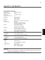
Specifications ......................................................................... 120
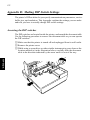
Making DIP Switch Settings................................................. 125
Memory Switch Settings ....................................................... 129
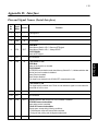
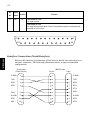
Interface ................................................................................. 130
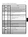
Peripheral Unit Driver Circuit............................................. 134
Please access the following URL
http://www.star-micronics.co.jp/service/sp_sup_e.htm
for the latest revision of the manual.
ENGLISH
TABLE OF CONTENTS
1
ENGLISH
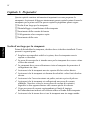
Chapter 1: Printer Setup
This chapter contains important information on setting up your printer. Be sure
to read this chapter carefully before using the printer for the first time. In this
chapter you will learn about:
❏
❏
❏
❏
❏
Choosing a place for the printer
Unpacking and setting up the printer
Installing the ribbon cassette
Connecting to a host computer
Inserting paper
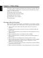
Choosing a place for the printer
Before actually unpacking the printer, you should take a few minutes to think
about where you plan to use it. Remember the following points when doing this.
✓ Choose a firm, level surface where the printer will not be exposed to
vibration.
✓ The power outlet you plan to connect to for power should be nearby and
✓
✓
✓
✓
✓
✓
✓
unobstructed.
Make sure that the printer is close enough to your host computer for you to
connect the two.
Make sure that the printer is not exposed to direct sunlight.
Make sure that the printer is well away from heaters and other sources of
extreme heat.
Make sure that the surrounding area is clean, dry, and free of dust.
Make sure that the printer is connected to a reliable power outlet. It should
not be on the same electric circuit as copiers, refrigerators, or other
appliances that cause power spikes.
Use a power outlet that matches the power rating noted on the label affixed
to the bottom of your printer.
Make sure that the room where you are using the printer is not too humid.
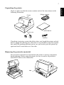
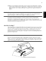
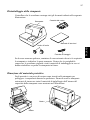
Unpacking the printer
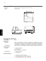
Check to make sure that the carton contains each of the items shown in the
following illustration.
Printer
Ribbon cassette
User’s Manual
Ferrite core
Fastener
If anything is missing, contact the dealer where you bought the printer and ask
them to supply the missing part. Note that it is a good idea to keep the original
box and all the packing materials just in case you need to pack the printer up
again and send it somewhere at a later date.
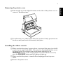
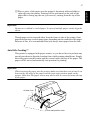
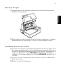
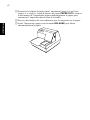
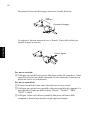
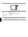
Removing the protective materials
Four protective materials are inserted into the printer to protect components
during shipping. Before using the printer, be sure to remove all protective
materials as shown in the illustration.
tape
tape
ENGLISH
2
3
ENGLISH
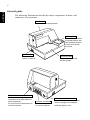
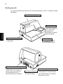
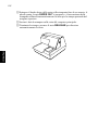
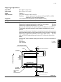
General guide
The following illustrations describe the major components, buttons, and
connectors of your printer.
Printer cover
Protects internal components.
Control panel
Three indicators show
the printer status, and
two switches provide
control over printer
functions.
Power switch
Turns printer
power on and off.
Peripheral unit connector cover
Covers a modular jack for
connection of a cash drawer or
other peripheral.
Do not connect a telephone line
to this connector.
Interface connector
For connection
to a host computer.
Document table
Supports the paper fed
into the printer.
AC adapter cable connector
For connection of the AC adapter.
Never unplug the AC adapter
while the printer is on.
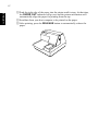
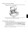
Removing the printer cover
❏ Push straight up on the ridged locations on the sides of the printer cover to
remove it from the printer.
❏ To replace the cover, slide it back down into position. Gently press down on
the cover until you hear it click securely into place.
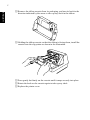
Installing the ribbon cassette
❏ Make sure that the printer’s paper release is activated (the paper is not held
❏
❏
in place by the paper feed roller). If it cannot be determined whether or not
the paper release is activated, turn on the printer and check if the
RELEASE indicator on the control panel is lit. If the indicator is not lit,
press the RELEASE button until the indicator lights up.
Make sure that the printer is turned off and unplugged from its power
outlet.
Remove the printer cover.
ENGLISH
4
5
ENGLISH
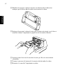
❏ Remove the ribbon cassette from its packaging, and turn its knob in the
direction indicated by the arrow to take up any slack in the ribbon.
❏ Holding the ribbon cassette so that the ribbon is facing down, install the
cassette into the slip printer as shown in the illustration.
❏ Press gently but firmly on the cassette until it snaps securely into place.
❏ Rotate the knob on the cassette again to take up any slack.
❏ Replace the printer cover.
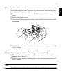
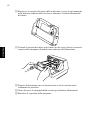
Removing the ribbon cassette
Use the following procedure to remove the ribbon cassette from the slip printer
when you want to replace it with a new one.
❏ Make sure that the printer is turned off and unplugged from its power
❏
❏
outlet.
Remove the printer cover.
Grasping the ribbon cassette as shown, gently pull it away from the printing
mechanism.
❏ Use the procedure under “Installing the ribbon cassette” on page 4 to install
a new cassette.
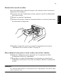
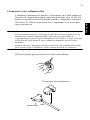
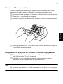
Connecting to a power outlet and turning power on and off
❏ Plug the AC adapter that comes with the printer into the printer’s AC
❏
adapter cable connector.
Connect a three-prong grounded power cord to the power cord connector of
the AC adapter.
Note:
The printer does not come with a power cord, so you must provide one yourself.
ENGLISH
6
7
ENGLISH
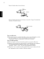
❏ Plug the other end of the power cord to a standard household wall outlet.
❏ Use the power switch on the left side of the printer to turn power on and off.
Important!
We recommend that you unplug the printer from the power outlet whenever you
do not plan to use it for long periods. Because of this, you should locate the
printer so that the power outlet it is plugged into is nearby and easy to access.
At this point you may want to perform a test of the printer to make sure it is
working properly. See page 15 for details on how to test the printer.
Connecting to your host computer
The computer sends data to the printer through a cable to the printer’s interface
(Serial Interface Connector Type: D-sub 25-pin or Parallel Interface Connector
Type: 36-pin Centronics compatible). This printer does not come with a cable,
so it is up to you to obtain one that suits your needs.
Important!
• The following instructions apply to the cable that is used with an IBMcompatible personal computer. Note that they do not apply to all types of
computers and cables. If you are unsure about what type of cable you should
use to connect with your computer, consult your dealer.
• Make sure that the printer is turned off and unplugged from the AC outlet and
that the computer is turned off before connecting them.
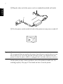
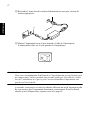
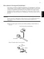
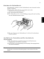
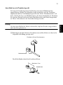
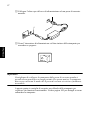
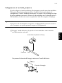
❏ Affix the larger ferrite core onto the cable as shown in the illustration
below.
Ferrite core (28 mm diameter)
Cable
Serial Interface
ENGLISH
8
9
ENGLISH
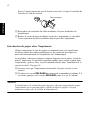
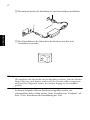
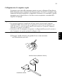
Pass the fastener through the ferrite core.
5 cm
maximum
Fastener
Loop the fastener around the cable and lock it. Use scissors to cut off any
excess.
Pull and cut
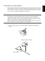
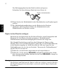
For a serial cable:
❏ Plug one end of the serial cable into the serial port of your computer, and
the other end of the cable into the socket on the back of the printer. Secure
both connectors in place with the screws that are provided.
For a parallel cable:
❏ Attach a ferrite core in the same way that one is attached to a serial cable.
❏ Plug one end of the parallel cable into the parallel port of your computer.
❏
The parallel port should be labeled “Printer”, “Parallel”, “PRN”, “LPT1” or
something similar.
Plug the other end of the parallel cable into the socket on the side of the
printer and secure it in place with the clips.
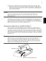
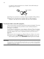
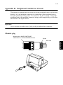
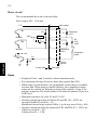
Connecting to a peripheral unit
You can connect a peripheral unit to the printer using a modular plug. The
following describes how to install the ferrite core and make the actual
connection. See “Modular plug” on page 134 for details about the type of
modular plug that is required. Note that this printer does not come with a
modular plug or wire, so it is up to you to obtain one that suits your needs.
Important!
Make sure that the printer is turned off and unplugged from the AC outlet and
that the computer is turned off before making connections.
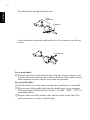
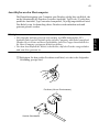
❏ Affix the smaller ferrite core onto the modular wire as shown in the
illustration below.
Ferrite core (20 mm diameter)
Connector Cable
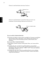
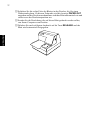
Pass the fastener through the ferrite core.
5 cm
maximum
Fastener
ENGLISH
10
11
ENGLISH
Loop the fastener around the cable and lock it. Use scissors to cut off any
excess.
Pull and cut
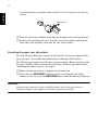
❏ Plug one end of the modular cable into the modular jack of the peripheral.
❏ Remove the modular jack cover from the back of the printer and plug the
other end of the modular cable into the jack of the printer.
Inserting the paper into the printer
Use only the specified type of paper for this printer. Do not use inappropriate
types of paper, or it could cause malfunction or damage of the printer.
The following procedure describes how to print on paper. Before trying to print,
be sure to install a ribbon cassette into the printer using the procedure under
“Installing the ribbon cassette” on page 4.
❏ Make sure that the printer is plugged in and turned on.
❏ Check that the RELEASE indicator on the control panel is lit. If the
indicator is not lit, press the RELEASE button until the indicator lights up.
Important!
Insertion and removal of paper should be done only when the printer is
released condition (the paper is not held by paper feed roller).
❏ Place a piece of the paper onto the printer’s document table and slide its
right edge into the printer. Printing will be performed on the side of the
paper that is facing up (the one you can see), starting from the top of the
paper.
Important!
Do not use wrinkled or curled paper. In case of multiple paper, neatly align the
sheets.
Though paper can be inserted either from the front or side of the printer, front
paper insertion may result in paper jams, depending on the condition of the paper.
Because of this, it is recommended that you always insert paper from the side.
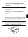
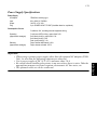
AutoSide Loading
This printer is equipped with paper sensors, so you do not have to perform any
special procedure to align the location from which printing should start. Simply
insert the paper into the printer and the sensor locates the top of the paper. The
paper will be moved automatically into position for printing.
Important!
When inserting the paper into the printer, make sure that there are at least 3 cm
between the top edge of the paper and the print start position mark on the
printer. Otherwise the paper sensor may not be able to correctly locate the top
of the paper.
At least 3 cm
Print start position mark
ENGLISH
12
13
ENGLISH
❏ Push the right edge of the paper into the printer until it stops. At that time,
the PAPER OUT indicator will go out, and the printer mechanism will
automatically align the paper for printing from the top.
❏ Send data from your host computer to be printed on the paper.
❏ After printing, press the RELEASE button to automatically release the
paper.
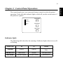
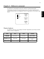
Chapter 2: Control Panel Operations
The control panel gives you some push-button control over the slip printer
operation. It also includes indicator lights, which tell you the current status of
the printer at a glance.
FORWARD
POWER
RELEASE
PAPER
OUT
REVERSE
RELEASE
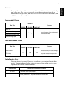
Indicator lights
The following table describes the meaning of indicator lights when it is on, off,
or flashing.
Indicator Light
Off
On
Flashing
POWER
Power off
Power on
Dot Alignment Adjust
Mode
PAPER OUT
Paper inserted
No paper
Insert paper prompt
RELEASE
Slip paper engaged
Slip paper released
Mechanical error
ENGLISH
14
15
ENGLISH
Buttons
The following table describes the function of the three control buttons of the
control panel.
Button
Description
FORWARD
Feeds the slip paper forward, toward the back of the printer. One press
feeds one line, holding down performs continuous feed.
REVERSE
Feeds the slip paper back, toward the front of the printer. One press
feeds one line, holding down performs continuous feed.
RELEASE
Activates the printer’s paper release (the paper is not held in place by
the paper feed roller).
Clears recoverable errors.
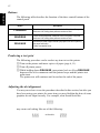
Producing a test print
The following procedure can be used at any time to test the printer.
❏ Turn on the printer and insert a piece of paper (page 6, 11).
❏ Turn off printer power.
❏ While holding down RELEASE, turn printer back on. Keep RELEASE
depressed for a few moments until the printer beeps and the printer test
print starts.
The printer test will continue until it reaches the end of the paper.
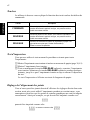
Adjusting the dot alignment
You may never have to use the procedure described in this section, but after you
have been using your printer for some time you may find that the dots of some
graphics do not align correctly. For example, what should look like:
may come out looking like one of the following:
or like this
This is caused when mechanical parts of the printer get out of alignment. This
happens only rarely and you may never experience it at all throughout the life
of the printer. If you do have problems, use the following procedure to correct it.
❏ Turn on the printer and insert a piece of paper.
❏ Turn off printer power.
❏ While holding down the control panel’s FORWARD and REVERSE
buttons, turn the printer back on to enter the Dot Alignment Adjust Mode,
which is indicator by a flashing POWER indicator flashes.
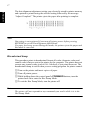
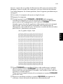
Entering the Dot Alignment Adjust Mode causes seven blocks to be printed,
each of which indicates a dot alignment setting, as shown below. An asterisk
to the left of the blocks indicates which block is currently selected.
❏ Use FORWARD to specify the block that appears to have the best aligned
❏
characters. Press FORWARD once to specify the first block, twice to
specify the second block, and so on up to seven times to specify the seventh
block.
Warning beep will sound if you press FORWARD more than seven times.
After specifying a block, press REVERSE to register your selection and
exit the Dot Alignment Adjust Mode.
ENGLISH
16
17
ENGLISH
The dots alignment adjustment setting you selected is stored in printer memory
and a pattern is printed using the selected setting followed by the message
“Adjust Complete!” The printer ejects the paper after printing is complete.
Note:
You setting is not registered if you turn off printer power before pressing
REVERSE to exit the Dot Alignment Adjust Mode.
If a paper feed error occurs during this mode, the printer ejects the paper and
this mode is cancelled.
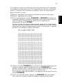
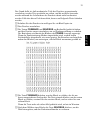
Hexadecimal dump
This procedure prints in hexadecimal format all codes (character codes and
control codes) that are sent to the printer by the computer. The printer does not
execute any control codes (such as 0A - linefeed), it just prints them out. The
hexadecimal dump is useful when you are writing programs for printer control.
❏ Turn on the printer and insert a piece of paper.
❏ Turn off printer power.
❏ While holding down the control panel’s FORWARD buttons, turn the
❏
printer back on to enter the Hex Dump Mode.
To exit the Hex Dump Mode, turn the printer off.
Note:
The printer will not responde to any commands you send it while it is in the
Hex Dump Mode.
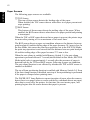
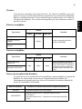
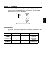
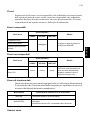
Errors
There are three types of errors: recoverable errors that require some action by
you before they clear, non-recoverable errors that require servicing by an
authorized service provider, and a data receive error. Errors are indicated by and
audible buzzer and the indicators.
Recoverable Errors
Indicators
Error Type
Recovery
POWER
RELEASE
PAPER OUT
Paper jam
Carriage motor lockup
Correct the cause of the problem and
then press RELEASE.
Flashing
Abnormal home position signal
Abnormal timing signal
Non-recoverable Errors
Indicators
Error Type
Recovery
POWER
RELEASE
PAPER OUT
RAM read/write
Off
On
CPU lockup
On
Turn off the printer, then after waiting a
few minutes, turn the printer back on. If
the printer does not recover, contact
your nearest service provider.
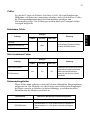
Data Receive Error
This type of error is caused whenever a problem is encountered during data
receipt. The method used by the printer to recover from a data receive error
depends on the current command mode.
Command mode
Star mode
ESC/POS mode
Data Receive Error Recover Procedure
The printer prints a question mark.
Memory switch 4-0=0 : The printer prints a question mark.
Memory switch 4-0=1 : The printer discards the received data.
ENGLISH
18
19
ENGLISH
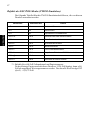
Paper Sensors
The following paper sensors are available.
❏ TOF Sensor
❏
This top-of-form sensor detects the leading edge of the paper.
When enabled, the TOF sensor detects when there is no paper present and
stops printing.
BOF Sensor
This bottom-of-form sensor detects the trailing edge of the paper. When
enabled, the BOF sensor detects when there is no paper present and printing
is interrupted.
When the TOF or BOF sensor detects that no paper is present, the printer stops
its motor after printing of 0 to a maximum of two more lines.
The BOF sensor detects a paper out condition whenever the distance between
print head pin #9 and the trailing edge of the paper becomes 38.1 mm or less. In
the Star Mode, this enters the print stop operation, but in the ESC/POS Mode,
the print stop operation is not entered until the distance between print head pin
#9 and the trailing edge of the paper becomes 27.3 mm or less.
When the auto clamp is enabled with Memory Switch 5-1, the auto clamp
operation is performed about 0.7 second (initial default in Star Mode; ESC/POS
Mode initial value is approximately 1 second) after the presence of paper is
detected both by the TOF and BOF sensors, following a paper out condition.
The auto clamp function is not affected by whether the TOF or BOF sensor is
enabled or disabled.
The top of form positioning function is enabled with Memory Switch 5-0. Even
if the auto clamp function is disabled, auto top of form positioning is performed
if the paper is clamped when printing starts.
The PAPER OUT lamp flashes to request insertion of paper when the sensors
detect there is no paper (when a sensor enabled by command detects no paper)
after data is received by the printer. At that time, the user inserts paper, and
printing begins after the sensor detects that paper is present.
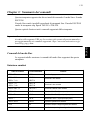
Chapter 3: Command Summary
This printer supports two different command modes: the Star mode and the
ESC/POS mode.
The Star mode emulates previous Star printers. The ESC/POS mode emulates
the Epson TM-295 or TM-290 slip printer.
This chapter provides you with all of the commands supported by this printer.
Important!
Access the following URL for the latest version of this manual and for updates
on supported commands: http://www.star-micronics.co.jp/service/
sp_sup_e.htm
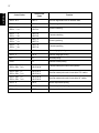
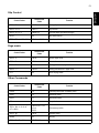
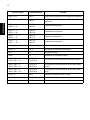
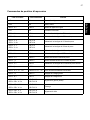
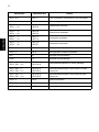
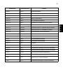
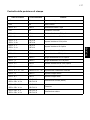
Star Mode Commands
The following tables show the Star mode commands that are supported by this
printer.
Character Selection
Hexadecimal
Codes
Control Codes
Function
<ESC> “R” n
1B 52 n
Selects the international character set
<ESC> “/” “1”
<ESC> “/” <1>
1B 2F 31
1B 2F 01
Selects slash zero
<ESC> “/” “0”
<ESC> “/” <0>
1B 2F 30
1B 2F 00
Selects normal zero
<ESC> <GS> “t” n
1B 1D 74 n
Selects the character code table
<ESC> “M”
1B 4D
Selects the 7 × 9 (half dot) font
<ESC> “P”
1B 50
Selects the 5 × 9 (2 pulses per dot) font
<ESC> “:”
1B 3A
Selects the 5 × 9 (3 pulses per dot) font
<ESC> <SP>n
1B 20 n
Sets character spacing
<SO>
0E
Sets the printing magnified double in character width
<DC4>
14
Resets the printing magnified in character width
ENGLISH
20
21
ENGLISH
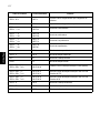
Hexadecimal
Codes
Control Codes
Function
<ESC> “W” n
1B 57 n
Sets the magnification rate in character width
<ESC> “h” n
1B 68 n
Sets the magnification rate in character height
<ESC> “–” “1”
<ESC> “–” <1>
1B 2D 31
1B 2D 01
Selects underlining
<ESC> “–” “0”
<ESC> “–” <0>
1B 2D 30
1B 2D 00
Cancels underlining
<ESC> “_” “1”
<ESC> “_” <1>
1B 5F 31
1B 5F 01
Selects upperlining
<ESC> “_” “0”
<ESC> “_” <0>
1B 5F 30
1B 5F 00
Cancels upperlining
<ESC> “4”
1B 34
Selects highlight printing
<ESC> “5”
1B 35
Cancels unhighlight printing
<SI>
0F
Inverted printing
<DC2>
12
Cancels inverted printing
<ESC> <RS> “i” “0”
<ESC> <RS> “i” <0>
1B 1E 96 30
1B 1E 96 00
Cancels rotated print mode for text (Default)
<ESC> <RS> “i” “1”
<ESC> <RS> “i” <1>
1B 1E 96 31
1B 1E 96 01
Specifies rotated print mode for text with a 270˚ rotation.
<ESC> <RS> “i” “2”
<ESC> <RS> “i” <2>
1B 1E 96 32
1B 1E 96 02
Specifies rotated print mode for text with a 90˚ rotation.
<ESC> “E”
1B 45
Selects emphasized printing
<ESC> “F”
1B 46
Cancels emphasized printing
<ESC> “U” n
1B 55 n
Selects print direction
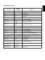
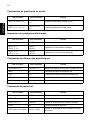
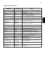
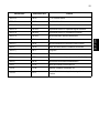
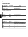
Print Position Control
Hexadecimal
Codes
Control Codes
Function
<LF>
0A
Line feed
<CR>
0D
Carriage Return
<ESC> “a” n
1B 61 n
Feeds paper n lines
<HT>
09
Horizontal tab
<ESC> “A” n
1B 41 n
Defines n/72-inch line spacing
<ESC> “2”
1B 32
Sets n/72-inch line spacing
<ESC> “z” “0”
<ESC> “z” <0>
1B 7A 30
1B 7A 00
Sets line spacing to 1/12-inch
<ESC> “z” “1”
<ESC> “z” <1>
1B 7A 31
1B 7A 01
Sets line spacing to 1/6-inch
<ESC> “0”
1B 30
Sets line spacing to 1/8-inch
<ESC> “1”
1B 31
Sets line spacing to 7/72-inch
<ESC> “J” n
1B 4A n
One time n/72-inch feed
<ESC> “j” n
1B 6A n
One time n/72-inch backfeed
<ESC> “3” n
1B 33 n
Sets line spacing to n/216-inch approximately
<ESC> “y”
1B 79 n
Sets line spacing to n/144-inch
<ESC> “D” n1 n2 ... <0>
1B 44 n1 n2 ... 00
Sets horizontal tab stops
<ESC> “l” n
1B 6C n
Sets left margin
<ESC> “Q” n
1B 51 n
Sets right margin
<ESC> <GS> “a” “0”
<ESC> <GS> “a” <0>
1B 1D 61 30
1B 1D 61 00
Left justification (Default)
<ESC> <GS> “a” “1”
<ESC> <GS> “a” <1>
1B 1D 61 31
1B 1D 61 01
Centering
<ESC> <GS> “a” “2”
<ESC> <GS> “a” <2>
1B 1D 61 32
1B 1D 61 02
Right justification
ENGLISH
22
23
ENGLISH
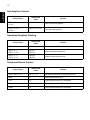
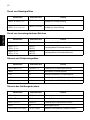
Dot Graphics Control
Hexadecimal
Codes
Control Codes
Function
<ESC> “K” n <0>
m1 m2 ...
1B 4B n 00 m1 m2
...
8 dot normal density graphics
<ESC> “L” n1 n2
m1 m2 ...
1B 4C n1 n2 m1 m2
...
8 dot high density graphics
Download Graphics Printing
Hexadecimal
Codes
Control Codes
Function
<ESC> “&” <0> n1 n2 ..
1B 26 00 n1 n2 ..
Defines download characters
<ESC> “%” “1”
<ESC> “%” <1>
1B 25 31
1B 25 01
Enables download character set
<ESC> “%” “0”
<ESC> “%” <0>
1B 25 30
1B 25 00
Disables download character set
Peripheral Device Control
Hexadecimal
Codes
Control Codes
Function
<ESC> <BEL> n1 n2
1B 07 n1 n2
Defines drive pulse width for peripheral device #1
<BEL>
07
Controls peripheral device #1
<FS>
1C
Controls peripheral device #1 immediately
<EM>
19
Controls peripheral device #2 immediately
<SUB>
1A
Controls peripheral device #2 immediately
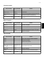
Slip Control
Hexadecimal
Codes
Control Codes
Function
<ESC> <SI> n
1B 0F n
Setting slip sensor
<ESC> <FF> n
1B 0C n
Slip function
<ESC> <VT> m n
1B 0B m n
Sets the paper eject direction/length
<EOT>
04
Slip status enquiry
<ESC><EM>mn<LF><NUL>
1B 19 n m 0A 00
Sets the wait time until the automatic clamp is activated
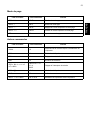
Page mode
Hexadecimal
Codes
Control Codes
Function
<ESC> “n”
1B 6E
Selects page mode
<ESC> “!”
1B 21
Selects line mode
<ESC> “*” ...
1B 2A ...
Setting print area in page mode
<ESC> “T” n
1B 54 n
Setting print direction in page mode
<FF>
0C
Prints in page mode
Other Commands
Hexadecimal
Codes
Control Codes
Function
<CAN>
18
Cancels printer buffer & Initialize printer
<DC3>
13
Deselects printer
<DC1>
11
Sets select mode
<RS>
1E
Beeps the buzzer
<ESC> “#N, n1 n2 n3 n4 ”
<LF> <NUL>
1B 23 N 2C n1 n2
n3 n4
0A 00
Sets memory switch
<ESC> “@”
1B 40
Initialize printer
<ENQ>
05
Enquiry
<ESC> “?” <LF> <NUL>
1B 3F 0A 00
Resets printer hardware and produce a test print
ENGLISH
24
25
ENGLISH
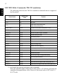
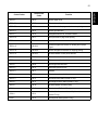
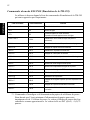
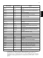
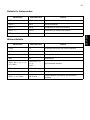
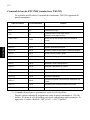
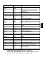
ESC/POS Mode Commands (TM-295 emulation)
The following table lists the TM-295 emulation commands that are supported
by this printer.
Hexadecimal
Codes
Control Codes
Function
<HT>
09
Horizontal tab
<LF>
0A
Line feed
<FF>
0C
Paper eject in single sheet mode
Paper mode print and return
<DLE> <EOT>
10 04
Enables real-time status send (Serial I/F only)
<CAN>
18
Cancels print data in page mode
<ESC> SP
1B 20
Sets size of space to right of character
<ESC> !
1B 21
Enables batch print mode
<ESC>#
1B 23
Sets memory switch
<ESC> %
1B 25
Enables/disables download character set
<ESC> &
1B26
Defines download character
<ESC> *
1B 2A
Selects bit image mode
<ESC> 2
1B 32
Selects 1/6-inch line spacing
<ESC> 3
1B 33
Selects approximate n/60-inch line spacing *1
<ESC> =
1B 3D
Selects peripheral device
<ESC> @
1B 40
Initializes the printer
<ESC> C
1B 43
Sets the eject length for single-sheet printing
<ESC> D
1B 44
Sets horizontal tab position
<ESC> F
1B 46
Enables/disables reverse feed for single-sheet mode
<ESC> J
1B 4A
Prints and n/60-inch (approximate value) paper feed *1
<ESC> K
1B 4B
Prints and n/60-inch (approximate value) reverse paper feed *1
*1: n/60-inch line spacing and paper feed commands:
Since the minimum paper feed pitch for this printer is 1/144 inch, n/60 inch can
considered an approximate value. However, the actual value is INT ((6n/5) +
0.5)/72 inch.
Control Codes
Hexadecimal
Codes
Function
<ESC> L
1B 4C
Selects page mode
<ESC> R
1B 52
Selects international character set
<ESC> T
1B 54
Selects direction for page mode character printing
<ESC> U
1B 55
Selects print direction
<ESC> V
1B 56
Designates/cancels 90˚ character rotation
<ESC> W
1B 57
Sets print area for page mode printing
<ESC> a
1B 61
Aligns position
<ESC> c3
1B 63 33
Selects the paper-end sensor for sending the no-paper
signal
<ESC> c4
1B 63 34
Selects the paper-end sensor for stopping printing
<ESC> c5
1B 63 35
Enables/disables control panel switches
<ESC> d
1B 64
Prints or feeds n lines
<ESC> e
1B 65
Prints or reverse feeds n lines
<ESC> f
1B 66
Sets single-sheet wait time
<ESC> p
1B 70
Generates specified pulse
<ESC> q
1B 71
Release
<ESC> t
1B 74
Selects character code table
<ESC> u
1B 75
Sends peripheral status (Serial I/F only)
<ESC> v
1B 76
Sends paper sensor status (Serial I/F only)
<ESC> {
1B 7B
Enables/disables inverted printing
<GS> I
1D 49
Sends printer ID (Serial I/F only)
<GS> a
1D 61
Enables/disables automatic send of printer status
(Serial I/F only)
<GS> r
1D 72
Sends printer status (Serial I/F only)
ENGLISH
26
27
ENGLISH
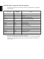
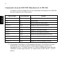
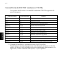
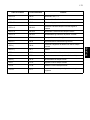
ESC/POS Mode Commands (TM-290 emulation)
The following table lists the TM-290 emulation commands that are supported
by this printer.
Hexadecimal
Codes
Control Codes
Function
<HT>
09
Horizontal tab
<LF>
0A
Line feed
<FF>
0C
Paper eject in single sheet mode
<ESC> SP
1B 20
Sets size of space to right of character
<ESC> !
1B 21
Enables batch print mode
<ESC>#
1B 23
Sets memory switch
<ESC> *
1B 2A
Selects bit image mode
<ESC> 2
1B 32
Selects 1/6-inch line spacing
<ESC> 3
1B 33
Selects approximate n/60-inch line spacing *1
<ESC> @
1B 40
Initializes the printer
<ESC> D
1B 44
Sets horizontal tab position
<ESC> M
1B 4D
Selects the 7× 9 font
<ESC> P
1B 50
Selects the 5× 9 font
*1: n/60-inch line spacing and paper feed commands:
Since the minimum paper feed pitch for this printer is 1/144 inch, n/60 inch can
considered an approximate value. However, the actual value is INT ((6n/5) +
0.5)/72 inch.
Control Codes
Hexadecimal
Codes
Function
<ESC> R
1B 52
Selects international character set
<ESC> c3
1B 63 33
Selects the paper-end sensor for sending the no-paper
signal
<ESC> c4
1B 63 34
Selects the paper-end sensor for stopping printing
<ESC> c5
1B 63 35
Enables/disables control panel switches
<ESC> d
1B 64
Prints or feeds n lines
<ESC> h
1B 68
Sets/Cancels reverse line feed
<ESC> j
1B 6A
Selects character width in vertical printing mode
<ESC> q
1B 71
Release
<ESC> t
1B 74
Selects character code table
<ESC> v n
1B 76 n
Requests paper sensor status (Serial I/F only)
<ESC> {
1B 7B
Enables/disables inverted printing
<FS> J
1C 4A
Sets vertical printing mode
<FS> K
1C 4B
Cancels vertical printing mode
<FS> W
1C 57
Sets/Cancels double-height, double-width printing
ENGLISH
28
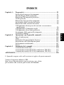
TABLE DES MATIÈRES
Configuration de l’imprimante............................................. 31
Emplacement de l’imprimante................................................. 31
Déballage de l’imprimante....................................................... 32
Retrait des matériaux de protection ......................................... 32
Description générale ................................................................ 33
Ouverture du capot................................................................... 34
Installation de la cassette à ruban ............................................ 34
Retrait de la cassette à ruban.................................................... 36
Raccordement à une prise secteur et mise sous et hors
tension.................................................................................... 36
Connexion à votre ordinateur-hôte .......................................... 38
Raccordement d’un appareil périphérique ............................... 40
Introduction du papier dans l’imprimante ............................... 41
AutoSide Loading ................................................................ 42
Chapitre 2: Tableau de commande........................................................... 44
Témoins lumineux ................................................................... 44
Touches.................................................................................... 45
Test d’impression..................................................................... 45
Réglage de l’alignement des points ......................................... 45
Vidage hexadécimal................................................................. 47
Erreurs...................................................................................... 48
Chapitre 3: Résumé des commandes ........................................................ 50
Les commandes du mode Star ................................................. 50
Commandes du mode ESC/POS (Émulation de la TM-295)... 55
Commandes du mode ESC/POS (Émulation de la TM-290)... 57
APPENDICE: ............................................................................................... 120
L’appendice n’est pas traduit.
Pour obtenir la dernière version de ce manuel, consultez l’adresse URL suivante :
http://www.star-micronics.co.jp/service/sp_sup_e.htm.
FRANÇAIS
Chapitre 1:
31
Chapitre 1: Configuration de l’imprimante
FRANÇAIS
Ce chapitre vous fournira des informations importantes vous permettant de
configurer votre imprimante. Veuillez lire attentivement ce chapitre avant
d’utiliser l’imprimante pour la première fois. Vous y trouverez des informations
qui vous aideront à :
❏
❏
❏
❏
❏
choisir l’emplacement de votre imprimante ;
déballer et configurer votre imprimante ;
installer la cassette à ruban ;
raccorder l’imprimante à un ordinateur-hôte ;
insérer un morceau de papier.
Emplacement de l’imprimante
Avant de déballer l’imprimante, déterminez l’emplacement où vous souhaitez
l’installer. Veuillez observer les points ci-dessous lors de votre choix.
✓ Choisissez une surface stable et de niveau sur laquelle l’imprimante ne sera
✓
✓
✓
✓
✓
✓
✓
✓
exposée à aucune vibration.
Assurez-vous que l’emplacement dispose d’une prise secteur proche et
d’accès aisé.
Assurez-vous que la distance entre l’imprimante et l’ordinateur-hôte vous
permet de les raccorder aisément.
Assurez-vous que l’imprimante n’est pas exposée directement aux rayons
du soleil.
Tenez l’imprimante à l’écart des sources de chaleur importante, telles que
les appareils de chauffage, etc.
Assurez-vous que le lieu où vous souhaitez installer l’imprimante est
propre, sec et n’est pas poussiéreux.
Assurez-vous que la prise secteur à laquelle vous raccordez l’imprimante
délivre une tension stable. Evitez de raccorder l’imprimante à la prise
secteur d’un circuit alimentant de gros consommateurs de courant, tels
qu’un photocopieur, réfrigérateur, etc.
Assurez-vous que la tension de la prise secteur correspond bien à la tension
nominale indiquée sur l’étiquette collée à la base de l’imprimante.
Assurez-vous que le lieu où vous installez l’imprimante n’est pas
excessivement humide.
32
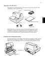
Déballage de l’imprimante
Contrôlez si la caisse contient bien tous les éléments illustrés ci-dessous.
Cassette à ruban
FRANÇAIS
Imprimante
Mode d’emploi
Tore de ferrite
Attache
Si l’un des éléments mentionnés ci-dessus ne se trouve pas dans la caisse,
adressez-vous au magasin où vous avez acheté l’imprimante et demandez que
la pièce manquante vous soit fournie. Il est préférable de conserver la caisse
d’origine ainsi que tous les emballages. Ceux-ci vous seront utiles s’il vous faut
emballer l’imprimante ou la transporter.
Retrait des matériaux de protection
Des feuilles de protection et un morceau de carton ont été insérés dans
l’imprimante pour protéger les composants lors du transport. Avant la mise en
service de l’imprimante, veillez à enlever tous les matériaux d’emballage sous
le capot, comme indiqué sur l’illustration.
Ruban
Ruban
33
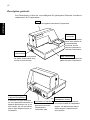
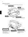
Description générale
Les illustrations ci-dessous vous indiquent les principaux éléments, touches et
connecteurs de l’imprimante.
FRANÇAIS
Capot
Protège les organes internes de l’imprimante.
Tableau de
commande
Ce tableau comprend
deux interrupteurs de
commande des
fonctions et trois
témoins indiquant le
statut de l’imprimante.
Interrupteur
d’alimentation
Cet interrupteur vous permet
de mettre l’imprimante sous
tension et hors tension.
Cache de pilotage
d’appareil périphérique
Il recouvre une pris modulaire
qui vous permet de raccorder un
appareil périphérique, tel qu’un
tiroir-caisse, etc. Ne connectez
pas de ligne téléphonique à ce
connecteur.
Connecteur d’interface
Ce connecteur vous
permet de connecter
l’imprimante à
l’ordinateur-hôte.
Table à document
Cette table sert de support au
papier fort pour l’impression.
Connecteur de câble
d’adaptateur secteur
Ce connecteur vous permet de
connecter le câble de l’adaptateur
secteur. Ne déconnectez pas le
câble lorsque l’imprimante est
sous tension.
34
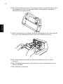
Ouverture du capot
❏ Appuyez droit sur les sections cannelées des deux côtés du capot pour le
FRANÇAIS
détacher de l’imprimante.
❏ Pour remettre le capot en place, glissez-le en place et rabaissez-le. Appuyez
délicatement sur le capot jusqu’à ce qu’il se verrouille dans un déclic.
Installation de la cassette à ruban
❏ Assurez-vous que le levier de libération du papier est activé (le papier n’est
❏
❏
pas maintenu en place par le rouleau d’alimentation du papier). Pour voir si
le levier de libération du papier est activé ou non, mettez l’imprimante sous
tension et vérifiez si le voyant RELEASE du panneau de commandes
s’allume. S’il est éteint, appuyez sur la touche RELEASE jusqu’à ce qu’il
s’allume.
Assurez-vous que l’imprimante est hors tension et qu’elle est débranchée
de la prise secteur.
Retirez le capot de l’imprimante.
35
❏ Déballez la cassette à ruban et tournez son bouton dans la direction
indiquée par la flèche afin de tendre correctement le ruban.
FRANÇAIS
❏ Saisissez la cassette à ruban de sorte que le ruban soit orienté vers le bas et
installez-la dans l’imprimante à papier fort de la manière illustrée.
❏ Appuyez sans forcer sur la cassette de sorte qu’elle soit correctement
❏
❏
verrouillée.
Tournez à nouveau le bouton de la cassette afin de tendre le ruban.
Remettez le capot de l’imprimante en place.
36
Retrait de la cassette à ruban
Suivez les instructions ci-dessous lorsque vous souhaitez retirer la cassette à
ruban afin de la remplacer.
❏
❏
de la prise secteur.
Retirez le capot de l’imprimante.
Saisissez la cassette à ruban de la manière illustrée et retirez-la doucement
du mécanisme d’impression.
❏ Installez la nouvelle cassette en suivant les instructions de la section
“Installation de la cassette à ruban” à la page 34.
Raccordement à une prise secteur et mise sous et hors tension
❏ Branchez l’adaptateur secteur optionnel sur le connecteur de câble
❏
d’adaptateur secteur de l’imprimante.
Raccordez un cordon d’alimentation à trois broches au connecteur de
l’adaptateur secteur prévu à cet effet en veillant à effectuer la connexion à
la terre.
Remarque:
Le cordon d’alimentation n’est pas fourni avec l’imprimante. Vous devrez donc
vous en procurer un.
FRANÇAIS
❏ Assurez-vous que l’imprimante est hors tension et qu’elle est débranchée
37
❏ Raccordez l’autre bout du cordon d’alimentation à une prise secteur de
tension appropriée.
FRANÇAIS
❏ Mettez l’imprimante sous et hors tension à l’aide de l’interrupteur
d’alimentation situé sur le côté gauche de l’imprimante.
Attention!
Nous vous recommandons de débrancher l’imprimante du secteur lorsque vous
ne comptez pas l’utiliser pendant une période prolongée. Par ailleurs, veillez
lors de l’installation à ce que la prise secteur alimentant l’imprimante soit
proche et d’accès facile.
A ce stade, vous pouvez si vous le souhaitez effectuer un test d’impression afin
de vous assurer que l’imprimante fonctionne correctement. Pour les détails
relatifs au test d’impression, reportez-vous à la page 45.
38
L’ordinateur communique les données à l’imprimante via le câble connecté à
l’interface de l’imprimante (type de connecteur d’interface série : D-Sub à 25
broches ou type de connecteur d’interface parallèle : compatible Centronics à
36 broches). Ce câble n’est pas fourni avec l’imprimante. Vous devrez donc
vous en procurer un.
Attention!
• Les instructions suivantes concernent le câble de connexion employé sur un
ordinateur personnel compatible IBM. Notez que ces instructions ne
s’appliquent pas à tous les types d’ordinateurs et de câbles. Si vous n’êtes pas
sûr du type de câble adapté à votre ordinateur, demandez conseil à votre
revendeur.
• Assurez-vous que l’imprimante est hors tension, qu’elle est débranchée de la
prise secteur et que l’ordinateur est hors tension avant de les connecter.
❏ Fixez la grande gaine en ferrite sur le câble comme illustré.
Tore de ferrite (28 mm de diamètre)
Câble
Interface série
FRANÇAIS
Connexion à votre ordinateur-hôte
39
Passez l’attache dans le tore de ferrite.
5 cm
maximum
FRANÇAIS
Attache
Passez l’attache autour du tore de ferrite et serrez-la. Coupez l’extrémité de
l’attache à l’aide de ciseaux.
Tirez et coupez
Pour un câble série:
❏ Raccordez l’une des extrémités du câble en série au port d’interface en série
de votre ordinateur, et l’autre extrémité dans la borne au dos de
l’imprimante. Fixez les connecteurs à l’aide des vis fournies.
Pour un câble parallèle:
❏ Fixez une gaine en ferrite de la même manière que pour le câble série.
❏ Branchez une extrémité du câble parallèle au port parallèle de l’ordinateur.
❏
Le port parallèle doit être identifié comme port d’ “Imprimante”,
“Parallèle”, “PRN”, “LPT1” ou toute autre appellation similaire.
Branchez l’autre extrémité du câble parallèle dans la prise située sur le côté
de l’imprimante et fixez le câble à l’aide des attaches.
40
Vous pouvez raccorder un appareil périphérique à l’imprimante à l’aide d’une
fiche modulaire. Nous expliquons ci-dessous comment installer le tore de ferrite
et faire le raccordement proprement dit. Pour les détails sur le type de fiche
modulaire à utiliser, reportez-vous à la page 134. Notez que le fil ou la fiche
modulaires ne sont pas fournis avec l’imprimante. Vous devrez donc vous les
procurer.
Attention!
Assurez-vous que l’imprimante est hors tension, qu’elle est débranchée de la
prise secteur et que l’ordinateur est hors tension avant d’effectuer les
connexions.
❏ Fixez la petite gaine en ferrite sur le câble modulaire comme illustré cidessous.
Tore de ferrite (20 mm de diamètre)
Connecteur
Câble
Passez l’attache dans le tore de ferrite.
5 cm
maximum
Attache
FRANÇAIS
Raccordement d’un appareil périphérique
41
Passez l’attache autour du tore de ferrite et serrez-la. Coupez l’extrémité de
l’attache à l’aide de ciseaux.
Tirez et coupez
FRANÇAIS
❏ Raccordez une extrémité du câble modulaire à la prise modulaire du
❏
périphérique.
Retirez le cache de prise modulaire au dos de l’imprimante, et raccordez
l’autre extrémité du câble modulaire dans la prise de l’imprimante.
Introduction du papier dans l’imprimante
Utilisez uniquement le type de papier recommandé pour cette imprimante.
N’utilisez jamais des papiers inadéquats car ils pourraient provoquer un
mauvais fonctionnement de l’imprimante ou l’endommager.
La procédure ci-dessous explique comment imprimer sur le papier. Avant de
tenter l’impression, il vous faut cependant installer une cassette à ruban dans
l’imprimante ; pour ce faire, voyez la méthode décrite dans “Installation de la
cassette à ruban” à la page 34.
❏ Assurez-vous que l’imprimante est branchée à la prise secteur et sous
tension.
❏ Vérifiez si le voyant RELEASE du panneau de commandes est allumé. S’il
est éteint, appuyez sur la touche RELEASE jusqu’à ce qu’il s’allume.
Attention!
L’introduction et le retrait du papier doivent s’effectuer uniquement lorsque
l’imprimante est en position papier relâché (lorsque le papier n’est pas
maintenu en place par le rouleau d’alimentation).
42
❏ Placez une feuille de papier dans le bac à papier de l’imprimante et faites
Attention!
Ne jamais utiliser de papier chiffonné ou recourbé. En cas d’utilisation de
papiers multiples, veillez à bien aligner les différentes feuilles.
Le papier peut être introduit par l’avant ou par le côté de l’imprimante.
Néanmoins, l’introduction du papier par l’avant risque de provoquer un
bourrage, en fonction de la condition du papier, et nous conseillons dès lors de
toujours introduire le papier par le côté.
AutoSide Loading
Cette imprimante est équipée de détecteurs de papier de sorte que vous ne devez
effectuer aucune opération spéciale pour aligner l’emplacement du début de
l’impression. Il suffit d’introduire le papier dans l’imprimante pour que le
détecteur localise le haut du papier. Le papier avancera automatiquement à la
position d’impression.
Attention!
Lors de l’insertion du papier dans l’imprimante, assurez-vous qu’il y a au
moins 3 cm entre le bord supérieur du papier et la marque situant le début de
l’impression sur l’imprimante. Sinon, le détecteur de papier risque de ne pas
situer correctement le haut du papier.
Au moins 3 cm
Marque de début d’impression
FRANÇAIS
glisser son bord droit vers l’imprimante. L’impression se fera sur la face du
papier tournée vers le haut (celle que l’on peut voir), à partir du haut du
papier.
43
❏ Poussez le bord droit du papier dans l’imprimante jusqu’à ce qu’il soit
FRANÇAIS
❏
❏
stoppé. A ce stade, le voyant d’absence de papier PAPER OUT s’éteint et
le mécanisme de l’imprimante aligne automatiquement le papier pour
commencer l’impression dans le haut de la feuille.
Envoyez des données de votre ordinateur pour les imprimer sur le papier.
Après l’impression, appuyez sur la touche RELEASE pour libérer
automatiquement le papier.
44
Le panneau de commandes permet de contrôler le fonctionnement de
l’imprimante de papier fort par boutons poussoir. Il contient également des
témoins lumineux qui vous indiquent l’état de l’imprimante en un simple coup
d’œil.
FORWARD
POWER
RELEASE
PAPER
OUT
REVERSE
RELEASE
Témoins lumineux
Le tableau ci-dessous vous explique l’état de l’imprimante pour chaque témoin
allumé, éteint ou clignotant.
Témoin
Eteint
Allumé
Clignotant
POWER
Hors tension
Sous tension
Mode de réglage
d’alignement des points
PAPER OUT
Papier inséré
Pas de papier
Demande d’insertion de
papier
RELEASE
Papier fort engagé
Papier fort libéré
Erreur mécanique
FRANÇAIS
Chapitre 2: Tableau de commande
45
Touches
Le tableau ci-dessous vous explique la fonction des trois touches du tableau de
commande.
FRANÇAIS
Touche
Description
FORWARD
Alimente le papier fort vers l’avant, vers le dos de l’imprimante. Une
pression fait avancer le papier d’une ligne, une pression continue
produit une avance continue.
REVERSE
Alimente le papier fort vers l’arrière, vers l’avant de l’imprimante. Une
pression fait avancer le papier d’une ligne, une pression continue
produit une avance continue.
RELEASE
Activation de la libération du papier de l’imprimante (le papier n’est
plus maintenu en place par le rouleau d’alimentation).
Efface les erreurs récupérables.
Test d’impression
Vous pouvez utiliser à tout moment la procédure suivante pour tester
l’imprimante.
❏ Mettez l’imprimante sous tension et insérez un morceau de papier (page 36, 41).
❏ Mettez l’imprimante hors tension.
❏ Tout en maintenant la touche RELEASE enfoncée, remettez l’imprimante
sous tension. Maintenez la touche RELEASE enfoncée pendant quelques
instants, jusqu’à ce que l’imprimante émette un bip et entame l’impression
du test.
Le test d’impression s’effectue sur toute la longueur du papier.
Réglage de l’alignement des points
Vous n’aurez peut-être jamais besoin d’effectuer les réglages décrits dans cette
section, mais près avoir utilisé l’imprimante pendant un certain temps, vous
remarquerez peut-être que les points de certains graphiques ne sont pas alignés
correctement. Ainsi par exemple, ce qui devrait être imprimé comme ceci :
pourrait être imprimé comme cela :
ou encore comme cela
46
❏ Mettez l’imprimante sous tension et introduisez un morceau de papier.
❏ Mettez l’imprimante hors tension.
❏ Tout en maintenant les touches FORWARD et REVERSE du tableau de
commande enfoncées, remettez l’imprimante sous tension afin d’activer le
mode de réglage d’alignement des points, qui est signalé par le
clignotement du témoin POWER.
Une fois le mode de réglage d’alignement des points activé, l’imprimante
imprime sept blocs de caractères de la manière indiquée ci-dessous, chacun
représentant un réglage d’alignement des points. Un astérisque (*) à gauche
des blocs vous indique le réglage sélectionné.
❏ Utilisez la touche FORWARD pour spécifier le bloc dont l’alignement des
❏
caractères semble optimal. Appuyez une fois sur FORWARD pour
spécifier le premier bloc, deux fois pour spécifier le deuxième bloc, et ainsi
de suite jusqu’à sept fois pour spécifier le septième bloc.
Un avertisseur sonore fait entendre si vous appuyez plus de sept fois sur la
touche FORWARD.
Après avoir spécifié un bloc, appuyez sur REVERSE pour sauvegarder
votre sélection et quitter le mode de réglage d’alignement des points.
FRANÇAIS
Ce problème est causé par un décalage des pièces mécaniques de l’imprimante.
Ce problème est relativement rare et il est possible que vous ne le rencontriez
jamais. Si toutefois vous rencontrez ce problème, suivez les instructions cidessous afin de le corriger.
47
Le réglage d’alignement des points que vous avez sélectionné est sauvegardé
dans la mémoire, et l’imprimante imprime une série de lignes graduées
correspondant à l’état d’impression sélectionné, suivie du message “Adjust
Completed!”, vous indiquant que le réglage est terminé. L’imprimante éjecte
ensuite le morceau de papier fort.
FRANÇAIS
Remarque:
Votre réglage ne sera pas sauvegardé si vous mettez l’imprimante hors tension
avant d’appuyer sur REVERSE pour quitter le mode de réglage d’alignement
des points. En cas d’erreur d’alimentation de papier dans ce mode,
l’imprimante éjecte le papier et le mode est annulé.
Vidage hexadécimal
Cette section vous indique comment imprimer en format hexadécimal tous les
codes (les codes de caractère et de commande) envoyés à l’imprimante par
l’ordinateur. L’imprimante n’exécute aucun code de commande (comme 0A
pour l’avance de ligne), mais les imprime simplement. Le vidage hexadécimal
vous sera utile lorsque vous écrivez des programmes de commande
d’imprimante.
❏ Mettez l’imprimante sous tension et introduisez un morceau de papier.
❏ Mettez l’imprimante hors tension.
❏ Tour en maintenant les touches FORWARD du tableau de commande
❏
enfoncées, remettez l’imprimante sous tension afin d’activer le mode de
vidage hexadécimal.
Pour quitter ce mode, mettez l’imprimante hors tension.
Remarque:
Quand l’imprimante est en mode de vidage hexadécimal, elle ne répond à
aucune commande.
48
Vous pouvez rencontrer trois types d’erreur : les erreurs corrigibles, que vous
pouvez corriger en effectuant certaines opérations, les erreurs non corrigibles,
dont la correction nécessite l’intervention d’un revendeur agréé, et l’erreur de
réception des données. Les erreurs sont signalées par un avertisseur sonore et
par des témoins.
Erreurs corrigibles
Témoins
Type d’erreur
Correction
POWER
RELEASE
PAPER OUT
Bourrage de papier
Blocage du moteur de
transport
Corrigez la cause du problème et
appuyez sur RELEASE.
Clignote
Signal de position d’origine
anormale
Erreurs corrigibles
Témoins
Type d’erreur
Correction
POWER
RELEASE
PAPER OUT
Lecture/écriture de la
mémoire vive
Eteint
Allumé
Allumé
Blocage de l’unité centrale
Mettez l’imprimante hors tension et
attendez quelques minutes avant de la
remettre sous tension. Si l’imprimante
ne réagit toujours pas normalement,
contactez le service technique le plus
proche.
Erreur de réception des données
Ce genre d’erreur se produit dès qu’un problème surgit pendant la réception de
données. Le moyen mis en oeuvre par l’imprimante pour rétablir son
fonctionnement normal après une erreur de réception de données dépend du
mode de commandes sélectionné.
Mode de commandes
Mode Star
Mode ESC/POS
Procédure de correction d’une erreur de réception des données
L’imprimante imprime un point d’interrogation.
Interrupteur mémoire 4+0=0 : l’imprimante imprime un point
d’interrogation.
Interrupteur mémoire 4+0=1 : l’imprimante ne conserve pas les données
reçues.
FRANÇAIS
Erreurs
49
Capteurs de papier
Les capteurs de papier suivants sont prévus.
❏ Capteur TOF
FRANÇAIS
❏
Ce capteur haut-de-page détecte le bord d’attaque du papier. Lorsqu’il est
validé, le capteur TOF détecte l’absence de papier et il arrête l’impression.
Capteur BOF
Ce capteur bas-de-page détecte le bord arrière du papier. Lorsqu’il est
validé, le capteur BOF détecte l’absence de papier et l’impression est
interrompue.
Lorsque la capteur TOF ou BOF détecte une absence de papier, l’imprimante
arrête son moteur après l’impression de 0 à un maximum de deux lignes
supplémentaires.
Le capteur BOF détecte une absence de papier chaque fois que la distance entre
la broche #9 de tête d’impression et le bord arrière du papier devient 38,1 mm
ou moins. En Mode Star, ceci fait passer à l’arrêt d’impression, mais en mode
ESC/POS, l’arrêt d’impression n’est pas atteint avant que la distance entre la
broche #9 de tête d’impression et le bord arrière ne devienne 27,3 mm ou moins.
Quand le blocage automatique est validé par l’Interrupteur de Mémoire 5-1, le
blocage automatique est exécuté environ 0,7 seconde (valeur initiale par défaut
en Mode Star; la valeur initiale en Mode ESC/POS est 1 seconde environ) après
que la présence de papier est détectée par les capteurs TOF et BOF, à la suite
d’une absence de papier. La fonction de blocage automatique n’est pas affectée
par l’état de validation ou d’invalidation du capteur TOF ou BOF.
La fonction (Positionnement haut de page) est valid ée par l’Interrupteur de
Mémoire 5-0. Même si la fonction de blocage automatique est invalidée, la
fonction automatique est exécutée sur le papier est verrouillée quand commence
l’impression.
Le voyant PAPER OUT clignote pour signaler le besoin d’insérer du papier
lorsque les capteurs détectent une absence de papier (quand un capteur validé
par une commande détecte une absence de papier) après réception de la donnée
par l’imprimante. A ce moment, l’utilisateur doit insérer du papier et
l’impression commence après que le capteur a détecté la présence de papier.
50
Chapitre 3: Résumé des commandes
Le mode Star émule les imprimantes Star précédentes. Le mode ESC/POS
émule l'imprimante de bordereaux TM-295 ou TM-290 Epson.
Ce chapitre donne la liste de toutes les commandes supportées par l’imprimante.
Attention!
Pour obtenir la dernière version de ce manuel et pour les mises à jour des
commandes supportées, consultez l’adresse URL suivante : http://www.starmicronics.co.jp/service/sp_sup_e.htm.
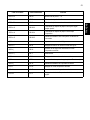
Les commandes du mode Star
Les tableaux ci-dessous vous montrent les commandes du mode Star qui sont
supportées par l’imprimante.
Sélection des caractères
Code de contrôle
Code hexadécimal
Fonction
<ESC> “R” n
1B 52 n
Sélection du jeu de caractères internationaux
<ESC> “/” “1”
<ESC> “/” <1>
1B 2F 31
1B 2F 01
Sélectionne le zéro barré
<ESC> “/” “0”
<ESC> “/” <0>
1B 2F 31
1B 2F 00
Sélectionne le zéro normal
<ESC> <GS> “t” n
1B 1D 74 n
Pour sélectionner un caractère dans le tableau des codes
<ESC> “M”
1B 4D
Sélection de la police 7 × 9 (demi-point)
<ESC> “P”
1B 50
Sélection de la police 5 × 9 (deux impulsions = 1 point)
<ESC> “:”
1B 3A
Sélection de la police 5 × 9 (trois impulsions = 1 point)
<ESC> <SP>n
1B 20 n
Réglage de l’espacement des caractères
<SO>
0E
Sélectionne la largeur double des caractères
<DC4>
14
Invalidation de la largeur double des caractères
FRANÇAIS
L’imprimante supporte deux modes de commande différents : le mode STAR,
et le mode ESC/POS.
51
Code de contrôle
<ESC> “W” n
Code hexadécimal
Fonction
1B 57 n
Règle l’indice d’amplification pour la largeur des caractères
1B 68 n
Règle l’indice d’amplification pour la hauteur des
caractères
<ESC> “–” “1”
<ESC> “–” <1>
1B 2D 31
1B 2D 01
Validation du soulignement
<ESC> “–” “0”
<ESC> “–” <0>
1B 2D 30
1B 2D 00
Invalidation du soulignement
<ESC> “_” “1”
<ESC> “_” <1>
1B 5F 31
1B 5F 01
Validation du surlignement
<ESC> “_” “0”
<ESC> “_” <0>
1B 5F 30
1B 5F00
Invalidation du surlignement
<ESC> “4”
1B 34
Validation de l’impression surintensifiée
<ESC> “5”
1B 35
Invalidation de l’impression surintensifiée
<SI>
0F
Impression inversée
<DC2>
12
Invalidation de l’impression inversée
<ESC> <RS> “i” “0”
<ESC> <RS> “i” <0>
1B 1E 96 30
1B 1E 96 00
Pour annuler le mode d'impression de texte avec rotation.
<ESC> <RS> “i” “1”
<ESC> <RS> “i” <1>
1B 1E 96 31
1B 1E 96 01
Pour spécifier le mode d'impression de texte avec rotation
de 270˚.
<ESC> <RS> “i” “2”
<ESC> <RS> “i” <2>
1B 1E 96 32
1B 1E 96 02
Pour spécifier le mode d'impression de texte avec rotation
de 90˚.
<ESC> “E”
1B 45
Validation de l’impression mise en valeur
<ESC> “F”
1B 46
Invalidation de l’impression mise en valeur
<ESC> “U” n
1B 55n
Sélection du sens d’impression
<ESC> “h” n
FRANÇAIS
52
Commandes de position d’impression
Code hexadécimal
Fonction
<LF>
0A
Avance d’une ligne
<CR>
0D
Retour chariot
<ESC> “a” n
1B 61 n
Avance du papier de n lignes
<HT>
09
Tabulation horizontale
<ESC> “A” n
1B 41 n
Sélection d’un interligne de n/72èmes de pouce
<ESC> “2”
1B 32
Validation d’un interligne de n/72èmes de pouce
<ESC> “z” “0”
<ESC> “z” <0>
1B 7A 30
1B 7A 00
Validation d’un interligne de 1/12ème de pouce
<ESC> “z” “1”
<ESC> “z” <1>
1B 7A 31
1B 7A 01
Validation d’un interligne de 1/6ème de pouce
<ESC> “0”
1B 30
Validation d’un interligne de 1/8ème de pouce
<ESC> “1”
1B 31
Validation d’un interligne de 7/72èmes de pouce
<ESC> “J” n
1B 4A n
Avance une fois de n/72èmes de pouce
<ESC> “j” n
1B 6A n
Avance inversée de une fois n/72èmes de pouce
<ESC> “3” n
1B 33 n
Validation d’un interligne de n/215èmes de pouce environ
<ESC> “y” n
1B 79 n
Validation d’un interligne de n/144èmes de pouce
<ESC> “D” n1 n2 .. <0>
1B 44 31 n1 n2 .. 00
Pose des arrêts de tabulation horizontaux
<ESC> “I” n
1B 6C n
Réglage de la marge gauche
<ESC> “Q” n
1B 51n
Réglage de la marge droite
<ESC> <GS> “a” “0”
<ESC> <GS> “a” <0>
1B 1D 61 30
1B 1D 61 00
Alignement à gauche (défaut)
<ESC> <GS> “a” “1”
<ESC> <GS> “a” <1>
1B 1D 61 31
1B 1D 61 01
Centrage
<ESC> <GS> “a” “2”
<ESC> <GS> “a” <2>
1B 1D 61 32
1B 1D 61 02
Alignement à droite
FRANÇAIS
Code de contrôle
53
Commandes de graphiques en points
Code de contrôle
Code hexadécimal
Fonction
FRANÇAIS
<ESC> “K” n<0>m1 m2 ...
1B 4B n 00 m1
m2...
Impression de graphiques à densité normale
<ESC> “L” n1 n2 m1 m2...
1B 4C n1 n2 m1
m2...
Impression de graphiques à haute densité
Impression de graphiques téléchargés
Code de contrôle
Code hexadécimal
Fonction
<ESC> “&” <0> n1 n2 ..
1B 26 00 n1 n2 ..
Définition des caractères à télécharger
<ESC> “%” “1”
<ESC> “%” <1>
1B 25 31
1B 25 01
Validation du jeu de caractères téléchargés
<ESC> “%” “0”
<ESC> “%” <0>
1B 25 30
1B 25 00
Invalidation du jeu de caractères téléchargés
Commande de pilotage des périphériques
Code de contrôle
Code hexadécimal
Fonction
<ESC> <BEL> n1 n2
1B 26 00 n1 n2 ..
Définition de l’impulsion d’entraînement du périphérique n°1
<BEL>
07
Commande de pilotage du périphérique n°1
<FS>
1C
Commande de pilotage immédiat du périphérique n°1
<EM>
19
Commande de pilotage immédiat du périphérique n°2
<SUB>
1A
Commande de pilotage immédiat du périphérique n°2
Commande de papier fort
Code de contrôle
Code hexadécimal
Fonction
<ESC> <SI> n
1B 0F n
Réglage du capteur de papier fort
<ESC> <FF> n
1B 0C n
Fonction de papier fort
<ESC> <VT> m n
1B 0B m n
Sélection du sens d’éjection/de la longueur du papier
<EOT>
04
Vérification de l’état du papier fort
<ESC><EM>mn<LF><NUL>
1B 19 n m 0A 00
Sélection du temps d’attente avant l’activation du blocage
automatique.
54
Mode de page
Code hexadécimal
Fonction
<ESC> “n”
1B 6E
Sélection du mode page
<ESC> “!”
1B 21
Sélection du mode ligne
<ESC> “*” ...
1B 2A ...
Réglage de la zone d’impression en mode page
<ESC> “T” n
1B 54 n
Sélection du sens d’impression en mode page
<FF>
0C
Impression en mode page
Autres commandes
Code de contrôle
Code hexadécimal
Fonction
<CAN>
18
Suppression de la mémoire tampon et réinitialisation de
l’imprimante
<DC3>
13
Désélection de l’imprimante
<DC1>
11
Réglage du mode de sélection
<RS>
1E
Activation de la sonnerie
<ESC> “#N, n1 n2 n3 n4”
<LF> <NUL>
1B 23 N 2C n1 n2
n3 n4
0A 00
Réglage de l’interrupteur de mémoire
<ESC> “@”
1B 40
Initialisation de l’imprimante
<ENQ>
05
Vérification
<ESC> “?” <LF> <NUL>
1B 3F 0A 00
Initialisation de l’imprimante et test d’impression
FRANÇAIS
Code de contrôle
55
Commandes du mode ESC/POS (Émulation de la TM-295)
Le tableau ci-dessous donne la liste des commandes d'émulation de la TM-295
qui sont supportées par l'imprimante.
FRANÇAIS
Code de contrôle
Code hexadécimal
Fonction
<HT>
09
Tabulation horizontale
<LF>
0A
Avance de ligne
<FF>
0C
Ejection du papier en mode une feuille
Impression en mode papier et retour à la ligne
10 04
Validation de l’envoi d’état en temps réel (série I/F
seulement)
<CAN>
18
Annulation des données d’impression en mode page
<ESC> SP
1B 20
Réglage de l’espace à droite du caractère
<ESC> !
1B 21
Validation de l’impression en mode lots
<ESC> #
1B 23
Réglage de l’interrupteur de mémoire
<ESC> %
1B 25
Validation/invalidation du jeu de caractères téléchargés
<ESC> &
1B26
Définition des caractères téléchargés
<ESC> *
1B 2A
Sélection du mode image en mode points
<ESC> 2
1B 32
Sélection d’un espacement de ligne de 1/6 pouce
<ESC> 3
1B 33
Validation de l’interligne de 7/60èmes de pouce environ *1
<ESC> =
1B 3D
Sélection du périphérique
<ESC> @
1B 40
Initialisation de l’imprimante
<ESC> C
1B 43
Réglage de la longueur d’éjection pour une impression une
feuille
<ESC> D
1B 44
Réglage de la position de tabulation horizontale
<ESC> F
1B 46
Validation/invalidation de l’avance inverse pour le mode
une feuille
<DLE> <EOT>
*1: Commandes d’interligne et d’alimentation du papier de n/60èmes de pouce :
Etant donné que l’écart minimum d’alimentation du papier pour cette
imprimante est de 1/144ème de pouce, la valeur n/60èmes de pouce doit être
considérée comme approximative. La valeur réelle est INT ((6n/5) + 0,5)/72
pouces.
56
Code hexadécimal
Fonction
<ESC> J
1B 4A
Imprime et fait avancer le papier de n/60èmes de pouce
environ *1
<ESC> K
1B 4B
Imprime et fait reculer le papier de n/60èmes de pouce
environ *1
<ESC> L
1B 4C
Sélection du mode page
<ESC> R
1B 52
Sélection du jeu de caractères internationaux
<ESC> T
1B 54
Sélection du sens d’impression pour l’impression des
caractères en mode page
<ESC> U
1B 55
Sélection du sens d’impression
<ESC> V
1B 56
Désignation/annulation de la rotation de 90˚ des caractères
<ESC> W
1B 57
Sélection de la zone d’impression pour l’impression en
mode page
<ES.....C> a
1B 61
Alignement de la position
<ESC> c3
1B 63 33
Commande au capteur de papier d’envoyer le signal
“papier épuisé”.
<ESC> c4
1B 63 34
Commande au capteur de papier d’interrompre l’impression.
<ESC> c5
1B 63 35
Validation/invalidation des interrupteurs du tableau de
commande
<ESC> d
1B 64
Impression ou avance de “n” lignes
<ESC> e
1B 65
Impression ou avance inverse de “n” lignes
<ESC> f
1B 66
Réglage du temps d’attente en mode une feuille
<ESC> p
1B 70
Génération de l’impulsion spécifiée
<ESC> q
1B 71
Relâchement
<ESC> t
1B 74
Réglage du tableau des codes de caractères
<ESC> u
1B 75
Envoi de l’état du périphérique (série I/F seulement)
<ESC> v
1B 76
Demande de l’état du capteur de papier (série I/F seulement)
<ESC> {
1B 7B
Validation/invalidation de l’impression inversée
<GS> I
1D 49
Envoi de l’ID imprimante (série I/F seulement)
<GS> a
1D 61
Validation/invalidation d’envoi automatique de l’état
d’imprimante (série I/F seulement)
<GS> r
1D 72
Envoi de l’état d’imprimante (série I/F seulement)
*1: Commandes d’interligne et d’alimentation du papier de n/60èmes de pouce :
Etant donné que l’écart minimum d’alimentation du papier pour cette
imprimante est de 1/144ème de pouce, la valeur n/60èmes de pouce doit être
considérée comme approximative. La valeur réelle est INT ((6n/5) + 0,5)/72
pouces.
FRANÇAIS
Code de contrôle
57
Commandes du mode ESC/POS (Émulation de la TM-290)
Le tableau ci-dessous donne la liste des commandes d'émulation de la TM-290
qui sont supportées par l'imprimante.
FRANÇAIS
Code de contrôle
Code hexadécimal
Fonction
<HT>
09
Tabulation horizontale
<LF>
0A
Avance de ligne
<FF>
0C
Ejection du papier en mode une feuille
<ESC> SP
1B 20
Réglage de l’espace à droite du caractère
<ESC> !
1B 21
Validation de l’impression en mode lots
<ESC> #
1B 23
Réglage de l’interrupteur de mémoire
<ESC> *
1B 2A
Sélection du mode image en mode points
<ESC> 2
1B 32
Sélection d’un espacement de ligne de 1/6 pouce
<ESC> 3
1B 33
Validation de l’interligne de 7/60èmes de pouce environ *1
<ESC> @
1B 40
Initialisation de l’imprimante
<ESC> D
1B 44
Réglage de la position de tabulation horizontale
*1: Commandes d’interligne et d’alimentation du papier de n/60èmes de pouce :
Etant donné que l’écart minimum d’alimentation du papier pour cette
imprimante est de 1/144ème de pouce, la valeur n/60èmes de pouce doit être
considérée comme approximative. La valeur réelle est INT ((6n/5) + 0,5)/72
pouces.
58
Code hexadécimal
Fonction
<ESC> M
1B 4D
Sélection de la police 7 × 9
<ESC> P
1B 50
Sélection de la police 5 × 9
<ESC> R
1B 52
Sélection du jeu de caractères internationaux
<ESC> c3
1B 63 33
Commande au capteur de papier d’envoyer le signal
“papier épuisé”.
<ESC> c4
1B 63 34
Commande au capteur de papier d’interrompre
l’impression.
<ESC> c5
1B 63 35
Validation/invalidation des interrupteurs du tableau de
commande
<ESC> d
1B 64
Impression ou avance de “n” lignes
<ESC> h
1B 68
Réglage/annulation de l'avance inverse des lignes
<ESC> j
1B 6A
Sélection de la largeur des caractères en mode
d'impression verticale
<ESC> q
1B 71
Relâchement
<ESC> t
1B 74
Réglage du tableau des codes de caractères
<ESC> v n
1B 76 n
Envoi de l’état du capteur de papier (série I/F seulement)
<ESC> {
1B 7B
Validation/invalidation de l’impression inversée
<FS> J
1C 4A
Réglage du mode d'impression verticale
<FS> K
1C 4B
Annulation du mode d'impression verticale
<FS> W
1C 57
Réglage/annulation de l'impression double hauteur, double
largeur
FRANÇAIS
Code de contrôle
INHALTSVERZEICHNIS
Drucker-Einrichtung ................................................................ 61
Wahl eines Aufstellungsorts für den Drucker............................. 61
Auspacken des Druckers............................................................. 62
Entfernen der Schutzmaterialien................................................. 62
Allgemeine Anleitung................................................................. 63
Abnehmen der Druckerabdeckung ............................................. 64
Einsetzen der Farbbandkassette .................................................. 64
Entnehmen der Farbbandkassette ............................................... 66
Anschluß an eine Netzsteckdose und Ein-/Ausschalten der
Netzversorgung....................................................................... 66
Anschließen an den Hostcomputer ............................................. 68
Anschluß an ein Peripheriegerät ................................................. 70
Papier in den Drucker einlegen................................................... 71
Automatischer Papiereinzug (AutoSide Loading) .................. 73
Kapitel 2: Bedienfeld .................................................................................. 74
Anzeigeleuchten ......................................................................... 74
Tasten.......................................................................................... 75
Erstellen eines Testdrucks .......................................................... 75
Einstellen der Punktausrichtung ................................................. 75
Sedezimaler Datenausdruck........................................................ 77
Fehler .......................................................................................... 78
Kapitel 3: Zusammenfassung der Befehle ................................................ 80
Befehle des Star-Modus.............................................................. 80
Befehle des ESC/POS-Modus (TM295 Emulation) ................... 85
Befehle des ESC/POS-Modus (TM290 Emulation) ................... 87
ANHANG: .................................................................................................. 120
Der Anhang der Bedienungsanleitung ist nur im englischen Sprache.
Bitte wenden Sie sich an die folgende Internet-Adresse:
http:\\www.star-micronics.co.jp/service/sp_sup_e.htm,
wenn Sie die neueste Revision dieses Handbuches lesen möchten.
DEUTSCH
Kapitel 1:
61
Kapitel 1: Drucker-Einrichtung
Dieses Kapitel enthält wichtige Informationen zur Vorbereitung Ihres Druckers.
Bitte dieses Kapitel sorgfältig durchlesen, bevor Sie den Drucker zum ersten
Mal in Betrieb nehmen. In diesem Kapitel erfahren Sie Einzelheiten über:
DEUTSCH
❏
❏
❏
❏
❏
Wahl eines Aufstellungsorts für den Drucker
Auspacken und Vorbereiten des Druckers
Einsetzen der Farbbandkassette
Anschließen an den Hostcomputer
Einsetzen des Papiers
Wahl eines Aufstellungsorts für den Drucker
Bevor Sie den Drucker auspacken, sollten Sie einige Minuten damit verbringen,
einen geeigneten Aufstellungsort auszusuchen. Denken Sie dabei an die
folgenden Punkte:
✓ Den Drucker auf einem flachen, aber festen Untergrund aufstellen, wo
✓
✓
✓
✓
✓
✓
✓
✓
keine Vibrationen vorhanden sind.
Die verwendete Steckdose soll in der Nähe und frei zugänglich sein.
Sicherstellen, daß der Drucker nahe genug am Computer ist, um die Geräte
mit dem Druckerkabel verbinden zu können.
Sicherstellen, daß der Drucker vor direktem Sonnenlicht geschützt ist.
Sicherstellen, daß der Drucker ausreichend weit von Heizkörpern entfernt
steht.
Dafür sorgen, daß die Umgebung des Druckers sauber, trocken und
staubfrei ist.
Sicherstellen, daß der Drucker an eine einwandfreie Stromzufuhr
angeschlossen ist. Er sollte nicht an Steckdosen angeschlossen werden, an
denen bereits Geräte mit möglichen Netzstörungen wie Kopierer,
Kühlschränke u.a. angeschlossen sind.
Die Versorgungsspannung muß dem Spannungswert auf dem Typenschild
an der Unterseite des Druckers entsprechen.
Den Drucker nicht an Orten mit hoher Luftfeuchtigkeit aufstellen.
62
Auspacken des Druckers
Überprüfen Sie den Kartoninhalt, und vergewissern Sie sich, daß alle unten
abgebildeten Teile vorhanden sind.
Farbbandkassette
Bedienungsanleitung
Ferritkern
Kabelbinder
Falls Teile fehlen, wenden Sie sich zwecks Nachlieferung bitte an den
Fachhandel, bei dem das Gerät gekauft wurde. Im Hinblick auf einen
eventuellen zukünftigen Transport des Druckers empfiehlt es sich, den
Lieferkarton und das gesamte Verpackungsmaterial aufzubewahren.
Entfernen der Schutzmaterialien
Schutzstreifen und ein Stück Pappe sind im Drucker eingelegt, um die internen
Bauteile beim Transport zu schützen. Vor der Inbetriebnahme des Druckers
müssen die in der Abbildung markierten Schutzmaterialien entfernt werden.
Klebeband
Klebeband
DEUTSCH
Drucker
63
Allgemeine Anleitung
Die folgenden Abbildungen zeigen die Hauptbauteile des Druckers.
Druckerabdeckung
Schützt interne Bauteile.
Bedienfeld
Drei Anzeigen zeigen den
Druckerzustand, und zwei
Schalter erlauben Steuerung
von Druckerfunktionen.
DEUTSCH
Netzschalter
Zum Ein- und Ausschalten
des Druckers.
Dokumentenauflage
Stützt das Quittungspapier, das in den
Quittungsdrucker eingeschoben wird.
Abdeckung der Buchse
für Peripheriegeräte
Deckt eine Modularbuchse zum
Anschluß einer Registrierkasse
oder eines anderen
angeschlossen Geräts ab. Hier
auf keinen Fall eine
Telefonleitung anschließen.
Schnittstellenbuchse
Zum Anschließen an den
Hostcomputer.
Netzteil-Anschlußbuchse
Zum Anschließen des
Betriebsstromkabels vom Netzteil.
Den Stecker nicht bei
eingeschaltetem Drucker
abziehen.
64
Abnehmen der Druckerabdeckung
❏ Die geriffelten Teile an den Druckerseiten gerade nach oben drücken, um
DEUTSCH
die Abdeckung abzunehmen.
❏ Zum Schließen die Abdeckung wieder nach unten aufsetzen. Vorsichtig
aufdrücken, bis sie hörbar einrastet.
Einsetzen der Farbbandkassette
❏ Stellen Sie sicher, daß die Papierfreigabe des Druckers aktiviert ist (das
❏
❏
Papier wird nicht von der Papier-Zufuhrrolle festgehalten). Sollten Sie
nicht feststellen können, ob die Papierfreigabe aktiv ist, schalten Sie den
Drucker ein und prüfen Sie, ob die Anzeige RELEASE am
Bedienungsfeld leuchtet. Sollte diese Anzeige nicht leuchten, drücken Sie
die Taste RELEASE so lange, bis diese Anzeige leuchtet.
Darauf achten, daß der Drucker ausgeschaltet und von der
Betriebsstromversorgung getrennt ist.
Die Abdeckung des Druckers abnehmen.
65
❏ Die Farbbandkassette aus der Verpackung nehmen, und den Knopf auf der
Farbbandkassette im Uhrzeigersinn drehen, um eventuell vorhandene
Bandschlaufen aufzuwickeln.
DEUTSCH
❏ Die Farbbandkassette so halten, daß das Farbband nach unten weist und die
Kassette in den Drucker einsetzen, wie in der Abbildung gezeigt.
❏ Die Farbbandkassette sanft aber fest herunterdrücken, bis sie hörbar
❏
❏
einrastet.
Den Farbband-Spannknopf auf der Kassette noch einmal drehen, um das
Band zu straffen.
Die Abdeckung aufsetzen.
66
Entnehmen der Farbbandkassette
Folgendermaßen verfahren, um die Farbbandkassette zum Austausch aus dem
Drucker zu nehmen.
❏ Sicherstellen, daß der Drucker ausgeschaltet und von der
DEUTSCH
❏
❏
Betriebsstromversorgung getrennt ist.
Die Druckerabdeckung abnehmen.
Die Farbbandkassette wie in der Abbildung gezeigt greifen und vorsichtig
aus dem Druckmechanismus ziehen.
❏ Die unter “Einsetzen der Farbbandkassette” auf Seite 64 beschriebenen
Schritte ausführen.
Anschluß an eine Netzsteckdose und Ein-/Ausschalten der
Netzversorgung
❏ Das mit dem Drucker mitgelieferte Netzteil an die BetriebsstromEingangsbuchse des Druckers anschließen.
❏ Ein Netzkabel mit Erdungsleitung an die dreipolige Netzeingangsbuchse
am Netzteil anschließen.
Hinweis:
Der Drucker wird nicht mit Netzkabel geliefert; dieses müssen Sie selber
stellen.
67
❏ Den anderen Stecker des Netzkabels an eine Netzsteckdose anschließen.
DEUTSCH
❏ Den Netzschalter an der linken Seite des Druckers zum Ein- und
Ausschalten verwenden.
Wichtig!
Wir empfehlen, den Netzstecker aus der Steckdose zu ziehen, wenn der Drucker
längere Zeit lang nicht benutzt werden soll. Der Drucker sollte vorzugsweise
an einem Platz aufgestellt werden, der leichten Zugang zur Netzsteckdose
gewährt.
Zu diesem Zeitpunkt sollte ein Druckertest ausgeführt werden, um
sicherzustellen, daß er richtig arbeitet. Siehe “Erstellen eines Testdrucks” auf
Seite 75 betr. Einzelheiten zur Durchführung des Tests.
68
Anschließen an den Hostcomputer
Wichtig!
• Die folgende Anleitung bezieht sich auf das von IBM-kompatiblen PCs
benutzte Kabel und ist deshalb nicht auf alle Computer und Kabel zutreffend.
Wenden Sie sich bitte an Ihren Fachhändler, falls Sie Fragen hinsichtlich des
für Ihren Computer geeigneten Kabeltyps haben.
• Vor dem Anschließen der Kabel sicherstellen, daß der Drucker ausgeschaltet
und vom Netz getrennt ist.
❏ Befestigen Sie den großen Ferritkern am Kabel, wie das in der folgenden
Abbildung gezeigt wird.
Ferritkern (28 mm Durchmesser)
Kabel
Serielle Schnittstelle
DEUTSCH
Die Datenübertragung vom Computer zum Drucker erfolgt über ein Kabel, das
an die Schnittstelle des Druckers (serieller Anschluß, Typ D-sub, 25 polig bzw.
paralleler Anschluß, Typ Centronics-kompatibel, 36 polig) angeschlossen wird.
Das Kabel ist im Lieferumfang dieses Druckers nicht enthalten und muß
getrennt gekauft werden.
69
Führen Sie den Kabelbinder durch den Ferritkern.
Maximum 5 cm
Kabelbinder
DEUTSCH
Führen Sie den Kabelbinder um das Kabel und sperren Sie ihn.
Schneiden Sie überschüssiges Band mit einer Schere ab.
Ziehen und abschneiden
Für ein serielles Schnittstellenkabel:
❏ Ein Ende des Kabels an den seriellen Anschluß des Computers anschließen
und das andere Ende an die Buchse an der Rückseite des Druckers an.
Wenn die Stecker durch Schrauben gesichert werden können, diese
festziehen.
Für ein paralleles Schnittstellenkabel:
❏ Befestigen Sie den Ferritkern auf die gleiche Weise, wie beim seriellen
❏
❏
Kabel.
Schließen Sie das eine Ende des parallelen Kabels an die parallele
Schnittstelle Ihres Computers an. Die parallele Schnittstelle sollte mit der
Bezeichnung “Drucker”, “Parallel”, “PRN”, “LPT1” oder einer ähnlichen
Bezeichnung versehen sein.
Schließen Sie das andere Ende des parallelen Kabels an den seitlichen
Anschluß des Druckers an, sichern Sie das Kabel mit den beiden dafür
vorgesehenen Klammern.
70
Anschluß an ein Peripheriegerät
Es kann ein Peripheriegerät an den Drucker mit einem Modularstecker
angeschlossen werden. Im folgenden wird beschrieben, wie der Ferritkern
angebracht und die Verbindung hergestellt wird. Siehe “Modularstecker” auf
Seite 134 für den Typ von Modularstecker, der dazu erforderlich ist. Beachten
Sie, daß der Drucker nicht mit einem Modularstecker oder Kabel ausgestattet
ist. Diese Teile müssen vom Anwender besorgt werden.
Vor dem Anschließen der Kabel sicherstellen, daß der Drucker ausgeschaltet
und vom Netz getrennt ist.
❏ Befestigen Sie den kleineren Ferritkern am seriellen Kabel, wie das in der
folgenden Abbildung gezeigt wird.
Ferritkern (20 mm Durchmesser)
Modularstecker
Kabel
Den Kabelbinder durch den Ferritkern führen.
Maximum 5 cm
Kabelbinder
DEUTSCH
Wichtig!
71
Das Befestigungsband um das Kabel wickeln und sperren.
Schneiden Sie überschüssiges Band mit einer Schere ab.
Ziehen und abschneiden
❏ Einen Stecker des Modularkabels in die Modularbuchse am Peripheriegerät
stecken.
DEUTSCH
❏ Die Modularbuchsenabdeckung von der Rückseite des Druckers
abnehmen, und den anderen Stecker des Modularkabels in die
Modularbuchse am Drucker stecken.
Papier in den Drucker einlegen
Benutzen Sie nur Papierarten, die für diesen Drucker speziell angegeben sind.
Benutzen Sie kein Papier, das nicht geeignet ist. Dadurch können
Fehlfunktionen und eine Beschädigung des Druckers die Folge sein.
Die folgende Beschreibung zeigt Ihnen das Einlegen des Papiers in den
Drucker. Bevor Sie zu drucken beginnen, prüfen Sie, ob eine Farbbandkassette
in den Drucker eingelegt ist. Sollte das nicht der Fall sein, legen Sie eine
Farbbandkassette ein, wie das im Abschnitt “Einsetzen der Farbbandkassette”
auf der Seite 64 zu sehen ist.
❏ Prüfen Sie, ob der Drucker angeschlossen und eingeschaltet ist.
❏ Prüfen Sie, ob die Anzeige RELEASE am Bedienungsfeld leuchtet. Sollte
diese Anzeige nicht leuchten, drücken Sie die Taste RELEASE so lange, bis
diese Anzeige leuchtet.
Wichtig!
Das Einlegen und Entfernen des Papiers sollte nur erfolgen, wenn der Drucker
das Papier freigegeben hat (das Papier wird nicht von der Papier-Zufuhrrolle
festgehalten).
72
❏ Legen Sie ein Blatt Papier auf den Dokumententisch des Druckers und
schieben Sie die rechte Ecke in den Drucker. Der Ausdruck erfolgt auf der
Seite, die nach oben zeigt (die Seite, die Sie sehen können) und beginnt am
oberen Rand des Blattes.
Wichtig!
Das Papier kann von vorne oder von der Seite in den Drucker eingelegt werden.
Es kann aber beim Einlegen von vorne, in Abhängigkeit vom Zustand des
Papiers, ein Papierstau verursacht werden. Aus diesem Grund wird empfohlen,
daß das Papier immer von der Seite eingelegt wird.
Automatischer Papiereinzug (AutoSide Loading )
Dieser Drucker ist mit einem Papiersensor ausgestattet, so daß Sie keine
besonderen Prozeduren durchführen müssen, um den Startpunkt einzustellen,
an dem der Ausdruck erfolgen soll. Legen Sie das Papier einfach in den Drucker
und der Sensor erkennt automatisch den oberen Rand des Papiers. Das Papier
wird dann automatisch in seine Startposition eingezogen, an der der Ausdruck
beginnen soll.
Wichtig!
Wenn Sie Papier in den Drucker legen, prüfen Sie, daß sich mindesten 3 cm
Platz zwischen dem oberen Rand des Blattes und der auf dem Drucker
markierten Startposition befinden. Sollte das nicht der Fall sein, kann der
Papiersensor das Blatt nicht erkennen und ist daher nicht in der Lage, das
Papier in seine Druckstartposition einzuziehen.
Mindestens 3 cm
Markierung der Druckstartposition
DEUTSCH
Benutzen Sie kein verknicktes oder verwelltes Papier. Im Falle eines
mehrseitigen Dokumentensatzes richten Sie alle einzelnen Seiten des
Dokumentes aus.
73
❏ Schieben Sie die rechte Ecke des Blattes in den Drucker, bis Sie einen
Widerstand spüren. Zu diesem Zeitpunkt wird die Anzeige PAPER OUT
ausgehen und der Druckermechanismus zieht das Blatt automatisch ein und
richtet es an der Druckstartposition aus.
❏ Senden Sie die Druckdaten, die auf dieses Blatt gedruckt werden sollen,
❏
von ihrem Computer zum Drucker.
Drücken Sie nach erfolgtem Ausdruck auf die Taste RELEASE und das
Blatt wird automatisch freigegeben.
DEUTSCH
74
Kapitel 2: Bedienfeld
Das Bedienungsfeld enthält einige Tasten, mit deren Hilfe Sie den Drucker
bedienen künnen. Es enthält auch einige LED-Anzeigen, die Sie über den
aktuellen Status des Druckers informieren.
FORWARD
POWER
RELEASE
REVERSE
DEUTSCH
PAPER
OUT
RELEASE
Anzeigeleuchten
Die folgende Tabelle stellt die Bedeutung des Leuchtens, Nichtleuchtens oder
Blinkens der Anzeigeleuchten dar.
Anzeigeleuchte
Aus
Ein
Blinkt
POWER
Ausgeschaltet
Eingeschaltet
PunktausrichtungEinstellmodus
PAPER OUT
Papier eingelegt
Kein Papier
Papier-EinlegenAufforderung
RELEASE
Quittungspapier
eingesetzt
Quittungspapier
freigegeben
Mechanischer Fehler
75
Tasten
Die folgende Tabelle stellt die Funktion der drei Steuertasten am Bedienfeld
dar.
Taste
Beschreibung
DEUTSCH
FORWARD
Drücken, um das Quittungspapier zur Rückseite des Druckers
zuzuführen. Ein Tastendruck schiebt um eine Zeile vor,
Gedrückthalten schiebt kontinuierlich vor.
REVERSE
Drücken , um das Quittungspapier zur Vorderseite des Druckers
zurückzuführen. Ein Tastendruck schiebt um eine Zeile vor,
Gedrückthalten schiebt kontinuierlich vor.
RELEASE
Aktiviert die Freigabe des Papiers (das Papier wird nicht von der
Papier-Zufuhrrolle festgehalten).
Löscht behebbare Fehler.
Erstellen eines Testdrucks
Mit Hilfe der folgenden Prozedur können Sie den Drucker zu jeder Zeit testen.
❏ Den Drucker einschalten, und ein Stück Papier einsetzen (Seite 66, 71).
❏ Den Drucker ausschalten.
❏ Die Taste RELEASE gedrückt gehalten, und den Drucker wieder
einschalten. RELEASE einige Sekunden lang gedrückt halten, bis der
Drucker einen Piepton abgibt und der Testdruck am Quittungsdrucker startet.
Der Quittungsdrucker-Test wird fortgesetzt, bis das Ende des Papiers
erreicht ist.
Einstellen der Punktausrichtung
Das hier beschriebene Verfahren wird nur selten nötig. Es kann aber
vorkommen, daß nach längerem Gebrauch des Druckers die Punkte einzelner
Grafiken nicht mehr richtig miteinander übereinstimmen. So kann z.B. was
folgendermaßen aussehen soll:
kann folgendermaßen aussehen:
oder wie
76
Der Grund dafür ist, daß mechanische Teile des Druckers gegeneinander
verschoben werden. Dies geschieht nur selten, und die meisten Anwender
werden während der Lebensdauer des Druckers damit nicht konfrontiert
werden. Falls aber dieses Problem auftritt, kann es auf folgende Weise behoben
werden.
und den Drucker erneut einschalten, um auf Punktausrichtung zu schalten.
Die Betriebsart wird durch das Blinken der POWER-Anzeige angezeigt.
Wenn der Punktjustierung-Modus eingeschaltet wird, werden sieben
Zeichenblöcke ausgedruckt, wie unten gezeigt. Ein Sternchen erscheint links
neben den Blöcken, um anzuzeigen, welcher Block momentan gewählt ist.
❏ Die Taste FORWARD drücken, um den Block zu wählen, der die am
❏
besten ausgerichteten Zeichen hat. Die Taste einmal drücken, um den ersten
Block zu wählen, zweimal für den zweiten Block, und so weiter bis zum
siebten Block.
Wenn die Taste mehr als sieben Mal gedrückt wird, ertönt ein Warnton.
Nach dem Wählen eines Blocks die Taste REVERSE drücken, um die
Wahl einzugeben, und den Punkteinstellmodus zu verlassen.
DEUTSCH
❏ Schalten Sie den Drucker ein und legen Sie ein Blatt Papier ein.
❏ Den Drucker ausschalten.
❏ Die Tasten FORWARD und REVERSE am Bedienfeld gedrückt halten,
77
Die Einstellungen für die Punktausrichtung werden im Druckerspeicher
gespeichert, und ein Muster wird mit der gewählten Einstellung ausgedruckt,
gefolgt von der Meldung “Adjust Complete!”. Der Drucker gibt das Papier nach
dem Druckvorgang aus.
DEUTSCH
Hinweis:
Wenn der Drucker ausgeschaltet wird, ohne die Taste REVERSE zum Verlassen
des Punkteinstellmodus zu drücken, werden die Einstellungen nicht
gespeichert. Tritt in diesem Modus ein Fehler beim Papiereinzug auf, wirft der
Drucker das Papier aus und bricht diesen Modus ab.
Sedezimaler Datenausdruck
Bei diesem Verfahren werden alle Codes (Zeichencodes und Steuercodes), die
vom Computer zum Drucker gesandt werden, in sedezimaler Form ausgedruckt.
Der Drucker führt dabei keine Steuercodes aus (wie etwa 0A - Zeilenvorschub),
sondern druckt sie nur aus. Der sedezimale Datenausdruck is nützlich, wenn
Programme zur Druckersteuerung geschrieben werden.
❏ Schalten Sie den Drucker ein und legen Sie ein Blatt Papier ein.
❏ Den Drucker ausschalten.
❏ Die Taste FORWARD am Bedienfeld gedrückt halten und den Drucker
❏
wieder einschalten, um auf Sedezimalen Datenausdruck zu schalten.
Zum Verlassen des Sedezimal-Datenausdruck-Modus den Drucker
ausschalten.
Hinweis:
Der Drucker reagiert nicht auf Befehle, die eingegeben werden, während er im
Sedezimal-Datenausdruck-Modus ist.
78
Fehler
Es gibt drei Typen von Fehlern: behebbare Fehler, die zum Beheben eine
Maßnahme von Seiten des Anwenders erfordern, und nicht behebbare Fehler,
die Wartungsmaßnahmen durch den Kundendienst erfordern, und
Datenempfangsfehler. Die Fehlertypen werden durch ein Tonsignal und die
Anzeigen dargestellt.
Anzeigen
Fehlertyp
Behebung
POWER
RELEASE
PAPER OUT
Papierstau
Wagenmotor-Blockierung
Die Ursache des Problems beheben,
und dann RELEASE drücken.
Blinkt
Falsches Grundstellungssignal
Nicht behebbare Fehler
Anzeigen
Fehlertyp
Behebung
POWER
RELEASE
PAPER OUT
RAM Lesen/Schreiben
Aus
CPU-Blockierung
Ein
Ein
Schalten Sie den Drucker aus und nach
einigen Minuten wieder ein.Sollte der
Fehler dann weiterhin auftreten,
wenden Sie sich an Ihren örtlichen
Fachhändler.
Datenempfangsfehler
Dieser Fehler kann auftreten, wenn ein Problem während des Datenempfanges
aufgetreten ist. Die Methode, wie der Drucker einen Fehler beim Empfangen
der Daten versucht zu beheben, ist davon abhängig, in welchen aktuellen
Befehlsmodus der Drucker geschaltet ist.
Befehlsmodus
Star-Modus
ESC/POS-Modus
Methode zur Behebung des Datenempfangsfehlers
Der Drucker druckt ein Fragezeichen.
Speicherschalter 4-0 = 0:Der Drucker druckt ein Fragezeichen.
Speicherschalter 4-0 = 1:Der Drucker löscht die empfangenen
Daten.
DEUTSCH
Behebbare Fehler
79
Papiersensoren
Die folgenden Papiersensoren stehen zur Verfügung.
❏ TOF-Sensor
❏
Dieser Vorderkantensensor (“top of form”) erkennt die Papiervorderkante.
Wenn er aktiviert ist, erkennt der TOF-Sensor, daß kein Papier vorhanden ist
und stoppt den Druckvorgang.
BOF-Sensor
Dieser Hinterkantensensor (“bottom of form”) erkennt die Hinterkante des
Papiers. Wenn er aktiviert ist, erkennt der BOF-Sensor, daß kein Papier
vorhanden ist und unterbricht den Druckvorgang.
DEUTSCH
Wenn der TOF- oder BOF-Sensor erkennt, daß kein Papier vorhanden ist,
stoppt der Drucker den Motor nach einem Druck von 0 bis maximal zwei
weiteren Zeilen.
Der Hinterkantensensor (BOF) erkennt den Papier-Verbraucht-Zustand, wenn
der Abstand zwischen dem Druckkopf-Pin Nr. 9 und der Hinterkante des
Papiers 38,1 mm oder weniger wird. Im Star-Modus wird dadurch der DruckStopp-Modus eingeschaltet, aber im ESC/POS-Modus wird der Druck-StoppModus nicht eingeschaltet, bevor der Abstand zwischen Druckkopf-Pin Nr. 9
und der Hinterkante des Papiers 27,3 mm oder weniger wird.
Wenn Auto-Festspannnen mit dem Memory-Schalter 5-1 aktiviert ist, wird der
Auto-Festspannen-Vorgang etwa 0,7 Sekunden (Vorgabewert im Star-Modus;
im ESC/POS-Modus ist der Vorgabewert etwa 1 Sekunde) nach dem Erkennen
des Vorhandenseins von Papier von sowohl dem TOF- als auch dem BOFSensor ausgeführt, nach einem Papier-Aus-Zustand. Die Auto-FestspannenFunktion wird nicht davon beeinflußt, ob der TOF- oder BOF-Sensor aktiviert
oder deaktiviert ist.
Die TOF-Positionierung Funktion wird mit dem Memory-Schalter 5-0 aktiviert.
Auch wenn die Auto-Festspannen-Funktion deaktiviert ist, wird die TOFPositionierung Funktion ausgeführt, wenn das Papier beim Druckstart
festgespannt ist.
Das Lämpchen PAPER OUT blinkt, um das Einführen von Papier auszuführen,
wenn die Sensoren erkennen, daß kein Papier vorhanden ist (wenn ein durch
Befehl aktivierter Sensor erkennt, daß Papier fehlt), nachdem Daten vom
Drucker empfangen werden.
Zu diesem Zeitpunkt setzt der Anwender Papier ein, und der Druck beginnt,
nachdem der Sensor erkennt, daß Papier vorhanden ist.
80
Kapitel 3: Zusammenfassung der Befehle
Dieser Drucker unterstützt zwei verschiedene Befehlsmodi: den Star-Modus
und den ESC/POS-Modus,
Der Star-Modus emuliert den Befehlssatz der Star-Drucker. Der Modus ESC/
POS emuliert den Epson TM295 oder TM-290 Quittungsdrucker.
Wichtig!
Die neueste Version dieser Anleitung und Aktualisierungen der unterstützten
Befehlssätze sind im Internet bei der folgenden URL erhältlich: http://
www.star-micronics.co.jp/service/sp_sup_e.htm
Befehle des Star-Modus
Die folgenden Tabellen zeigen die Star-Modus-Befehle, die von diesem
Drucker unterstützt werden.
Wählen von Zeichen
Steuerbefehle
Sedezimal-Codes
Funktion
<ESC> “R” n
1B 52 n
Internationalen Zeichensatz einstellen
<ESC> “/” “1”
<ESC> “/” <1>
1B 2F 31
1B 2F 01
Wahl einer Null mit Querstrich
<ESC> “/” “0”
<ESC> “/” <0>
1B 2F 30
1B 2F 00
Wahl einer Null ohne Querstrich
<ESC> <GS> “t” n
1B 1D 74 n
Wählt die Zeichencode-Tabelle
<ESC> “M”
1B 4D
7 × 9 (Halbpunkt) Schriftart wählen
<ESC> “P”
1B 50
5 × 9 (2 Impulse pro Punkt) Schriftart wählen
<ESC> “:”
1B 3A
5 × 9 (3 Impulse pro Punkt) Schriftart wählen
<ESC> <SP>n
1B 20 n
Zeichenabstand einstellen
<SO>
0E
Druck mit doppelter Zeichenbreite
<DC4>
14
Druck mit doppelter Zeichenbreite ausschalten
DEUTSCH
In diesem Kapitel werden alle von diesem Drucker unterstützten Befehle
aufgeführt.
81
Steuerbefehle
Sedezimal-Codes
Funktion
DEUTSCH
<ESC> “W” n
1B 57 n
Druck mit doppelter Zeichenbreite ein- bzw. ausschalten
<ESC> “h” n
1B 68 n
Druck mit doppelter Zeichenhöhe ein- bzw. ausschalten
<ESC> “–” “1”
<ESC> “–” <1>
1B 2D 31
1B 2D 01
Unterstreichen einschalten
<ESC> “–” “0”
<ESC> “–” <0>
1B 2D 30
1B 2D 00
Unterstreichen ausschalten
<ESC> “_” “1”
<ESC> “_” <1>
1B 5F 31
1B 5F 01
Überstreichen einschalten
<ESC> “_” “0”
<ESC> “_” <0>
1B 5F 30
1B 5F00
Überstreichen ausschalten
<ESC> “4”
1B 34
Hervorgehobener Ausdruck einschalten
<ESC> “5”
1B 35
Hervorgehobener Ausdruck ausschalten
<SI>
0F
Invertierter Druck einschalten
<DC2>
12
Invertierter Druck ausschalten
<ESC> <RS> “i” “0”
<ESC> <RS> “i” <0>
1B 1E 96 30
1B 1E 96 00
Hebt Rotationsdruckmodus für Text auf (Standard)
<ESC> <RS> “i” “1”
<ESC> <RS> “i” <1>
1B 1E 96 31
1B 1E 96 01
Gibt Rotationsdruckmodus für Text mit einer 270-GradDrehung ein.
<ESC> <RS> “i” “2”
<ESC> <RS> “i” <2>
1B 1E 96 32
1B 1E 96 02
Gibt Rotationsdruckmodus für Text mit einer 90-GradDrehung ein.
<ESC> “E”
1B 45
Fettdruck einschalten
<ESC> “F”
1B 46
Fettdruck ausschalten
<ESC> “U” n
1B 55n
Wahl der Druckrichtung
82
Ändern der Druckposition
Sedezimal-Codes
Funktion
<LF>
0A
Zeilenvorschub
<CR>
0D
Wagenrücklauf
<ESC> “a” n
1B 61 n
Papiervorschub n Zeilen einstellen
<HT>
09
Nächste horizontale Tabulatorposition
<ESC> “A” n
1B 41 n
Zeilenabstand n/72 Zoll definieren
<ESC> “2”
1B 32
Zeilenabstand von n/72 Zoll ausführen
<ESC> “z” “0”
<ESC> “z” <0>
1B 7A 30
1B 7A 00
Zeilenabstand 1/12 Zoll einstellen
<ESC> “z” “1”
<ESC> “z” <1>
1B 7A 31
1B 7A 01
Zeilenabstand 1/6 Zoll einstellen
<ESC> “0”
1B 30
Zeilenabstand 1/8 Zoll einstellen
<ESC> “1”
1B 31
Zeilenabstand 7/72 Zoll einstellen
<ESC> “J” n
1B 4A n
Einmaliger Zeilenvorschub von n/72 Zoll
<ESC> “j” n
1B 6A n
Einmaliger Zeilenrücktransport von n/72 Zoll
<ESC> “3” n
1B 33 n
Angenäherten Zeilenabstand n/216 Zoll einstellen
<ESC> “y” n
1B 79 n
Zeilenabstand n/144 Zoll einstellen
<ESC> “D” n1 n2 .. <0>
1B 44 31 n1 n2 .. 00
Horizontale Tabulatorpositionen setzen
<ESC> “l” n
1B 6C n
Linken Rand setzen
<ESC> “Q” n
1B 51 n
Rechten Rand setzen
<ESC> <GS> “a” “0”
<ESC> <GS> “a” <0>
1B 1D 61 30
1B 1D 61 00
Linksbündig (Standard)
<ESC> <GS> “a” “1”
<ESC> <GS> “a” <1>
1B 1D 61 31
1B 1D 61 01
Zentrieren
<ESC> <GS> “a” “2”
<ESC> <GS> “a” <2>
1B 1D 61 32
1B 1D 61 02
Rechtsbündig
DEUTSCH
Steuerbefehle
83
Druck von Rastergrafiken
Steuerbefehle
Sedezimal-Codes
Funktion
<ESC> “K” n<0>m1 m2 ...
1B 4B n 00 m1 m2
...
Grafikdruck in normaler Auflösung
<ESC> “L” n1 n2 m1 m2 ...
1B 4C n1 n2 m1 m2
...
Grafikdruck in hoher Auflösung
Druck von heruntergeladenen Zeichen
DEUTSCH
Steuerbefehle
Sedezimal-Codes
Funktion
<ESC> “&” <0> n1 n2 ..
1B 26 00 n1 n2 ..
Heruntergeladenes Zeichen definieren
<ESC> “%” “1”
<ESC> “%” <1>
1B 25 31
1B 25 01
Heruntergeladenen Zeichensatz aktivieren
<ESC> “%” “0”
<ESC> “%” <0>
1B 25 30
1B 25 00
Heruntergeladenen Zeichensatz deaktivieren
Steuern von Peripheriegeräten
Steuerbefehle
Sedezimal-Codes
Funktion
<ESC> <BEL> n1 n2
1B 26 00 n1 n2 ..
Treiberimpuls für Peripheriegerät definieren
<BEL>
07
Steuerbefehl für Peripheriegerät #1
<FS>
1C
Sofortiger Steuerbefehl für Peripheriegerät #1
<EM>
19
Sofortiger Steuerbefehl für Peripheriegerät #2
<SUB>
1A
Sofortiger Steuerbefehl für Peripheriegerät #2
Steuern des Quittungsdruckers
Steuerbefehle
Sedezimal-Codes
Funktion
<ESC> <SI> n
1B 0F n
Quittungs-Sensor einstellen
<ESC> <FF> n
1B 0C n
Quittungs-Funktion
<ESC> <VT> m n
1B 0B m n
Richtung/Länge für Papierauswurf einstellen
<EOT>
04
Quittungsstatus prüfen
<ESC><EM>mn<LF><NUL>
1B 19 n m 0A 00
Wartezeit für automatisches Einspannen einstellen
84
Befehle für Seitenmodus
Sedezimal-Codes
Funktion
<ESC> “n”
1B 6E
Seitenmodus wählen
<ESC> “!”
1B 21
Zeilenmodus wählen
<ESC> “*” ...
1B 2A ...
Druckbereich im Seitenmodus einstellen
<ESC> “T” n
1B 54 n
Druckrichtung im Seitenmodus einstellen
<FF>
0C
Im Seitenmodus drucken
Weitere Befehle
Steuerbefehle
Sedezimal-Codes
Funktion
<CAN>
18
Druckerspeicher löschen und Drucker initialisieren
<DC3>
13
Drucker Offline schalten
<DC1>
11
Drucker Online schalten
<RS>
1E
Druckersignal
<ESC> “#N, n1, n2, n3, n4”
<LF> <NUL>
1B 23 N 2C n1 n2
n3 n4
0A 00
Speicherschalter einstellen
<ESC> “@”
1B 40
Drucker initialisieren
<ENQ>
05
Anfrage
<ESC> “?” <LF> <NUL>
1B 3F 0A 00
Drucker-Hardware zurücksetzen und Testausdruck
ausführen
DEUTSCH
Steuerbefehle
85
Befehle des ESC/POS-Modus (TM295 Emulation)
Die folgende Tabelle führt die TM-295 Emulationsbefehle aus, die von diesem
Drucker unterstützt werden.
Steuerbefehle
Sedezimal-Codes
Funktion
DEUTSCH
<HT>
09
Horizontaler Tab
<LF>
0A
Zeilenvorschub
<FF>
0C
Papierauswurf im Einzelblattmodus
Papiermodus drucken und zurückschalten
10 04
Übertragung in Echtzeit aktivieren (nur serielle
Schnittstelle)
<CAN>
18
Druckdaten in Seitenmodus löschen
<ESC> SP
1B 20
Leerstelle rechts neben Zeichen einstellen
<ESC> !
1B 21
Batch-Druckmodus aktivieren
<ESC> #
1B 23
Speicherschalter einstellen
<ESC> %
1B 25
Heruntergeladenen Zeichensatz aktivieren/deaktivieren
<ESC> &
1B26
Heruntergeladenes Zeichen definieren
<ESC> *
1B 2A
Bitbildmodus wählen
<ESC> 2
1B 32
1/6-Zoll-Zeilenabstand wählen
<ESC> 3
1B 33
Angenäherten Zeilenabstand 7/60 Zoll einstellen *1
<ESC> =
1B 3D
Peripheriegerät wählen
<ESC> @
1B 40
Drucker initialisieren
<ESC> C
1B 43
Ausgabelänge für Einzelblattdruck einstellen
<ESC> D
1B 44
Horizontale Tab-Position einstellen
<ESC> F
1B 46
Rückwärtsvorschub für Einzelblattmodus aktivieren/
deaktivieren
<ESC> J
1B 4A
Ausdruck und n/60 Zoll (ungefährer Wert) Papiervorschub *1
<ESC> K
1B 4B
Ausdruck und n/60 Zoll (ungefährer Wert)
Papierrücktransport 1*
<DLE> <EOT>
*1: Befehle für n/60 Zoll Zeilenabstand und Papiertransport:
Da der kleinste Papiervorschub dieses Druckers 1/144 Zoll beträgt, kann n/60
Zoll als ungefährer Wert angenommen werden. Der aktuelle Wert beträgt: INT
((6n/5) + 0,5)/72 Zoll.
86
Sedezimal-Codes
Funktion
<ESC> L
1B 4C
Seitenmodus wählen
<ESC> R
1B 52
Internationalen Zeichensatz wählen
<ESC> T
1B 54
Richtung für Seitendruck-Zeichendruck wählen
<ESC> U
1B 55
Wahl der Druckrichtung
<ESC> V
1B 56
90˚ Zeichendrehung EIN/AUS
<ESC> W
1B 57
Druckbereich für Seitenmodus-Druck einstellen
<ESC> a
1B 61
Position ausrichten
<ESC> c3
1B 63 33
Papierende-Sensor für Papierende-Signal einstellenn
<ESC> c4
1B 63 34
Papierende-Sensor für Druckabbruch einstellen
<ESC> c5
1B 63 35
Bedienfeldschalter aktivieren/deaktivieren
<ESC> d
1B 64
n Zeilen drucken oder vorschieben
<ESC> e
1B 65
n Zeilen drucken oder zurückschieben
<ESC> f
1B 66
Einzelblatt-Wartezeit einstellen
<ESC> p
1B 70
Spezifizierten Impuls erzeugen
<ESC> q
1B 71
Freigeben
<ESC> t
1B 74
Zeichencodetabelle wählen
<ESC> u
1B 75
Peripheriestatus übertragen (nur serielle Schnittstelle)
<ESC> v
1B 76
Papiersensorstatus anfragen (nur serielle Schnittstelle)
<ESC> {
1B 7B
Invertierten Drucke aktivieren/deaktivieren
<GS> I
1D 49
Drucker-ID übertragen (nur serielle Schnittstelle)
<GS> a
1D 61
Automatische Übertragung des Druckerstatus aktivieren/
deaktivieren (nur serielle Schnittstelle)
<GS> r
1D 72
Druckerstatus übertragen (nur serielle Schnittstelle)
DEUTSCH
Steuerbefehle
87
Befehle des ESC/POS-Modus (TM290 Emulation)
Die folgende Tabelle führt die TM-290 Emulationsbefehle aus, die von diesem
Drucker unterstützt werden.
Steuerbefehle
Sedezimal-Codes
Funktion
DEUTSCH
<HT>
09
Horizontaler Tab
<LF>
0A
Zeilenvorschub
<FF>
0C
Papierauswurf im Einzelblattmodus
<ESC> SP
1B 20
Leerstelle rechts neben Zeichen einstellen
<ESC> !
1B 21
Batch-Druckmodus aktivieren
<ESC> #
1B 23
Speicherschalter einstellen
<ESC> *
1B 2A
Bitbildmodus wählen
<ESC> 2
1B 32
1/6-Zoll-Zeilenabstand wählen
<ESC> 3
1B 33
Angenäherten Zeilenabstand 7/60 Zoll einstellen *1
<ESC> @
1B 40
Drucker initialisieren
<ESC> D
1B 44
Horizontale Tab-Position einstellen
*1: Befehle für n/60 Zoll Zeilenabstand und Papiertransport:
Da der kleinste Papiervorschub dieses Druckers 1/144 Zoll beträgt, kann n/60
Zoll als ungefährer Wert angenommen werden. Der aktuelle Wert beträgt: INT
((6n/5) + 0,5)/72 Zoll.
88
Sedezimal-Codes
Funktion
<ESC> M
1B 4D
7 × 9 Schriftart wählen
<ESC> P
1B 50
5 × 9 Schriftart wählen
<ESC> R
1B 52
Internationalen Zeichensatz wählen
<ESC> c3
1B 63 33
Papierende-Sensor für Papierende-Signal einstellenn
<ESC> c4
1B 63 34
Papierende-Sensor für Druckabbruch einstellen
<ESC> c5
1B 63 35
Bedienfeldschalter aktivieren/deaktivieren
<ESC> d
1B 64
n Zeilen drucken oder vorschieben
<ESC> h
1B 68
Aktiviert/Deaktiviert den Rückwärts-Zeilenvorschub
<ESC> j
1B 6A
Wählt die Zeichenbreite im vertikalen Druckmodus
<ESC> q
1B 71
Freigeben
<ESC> t
1B 74
Zeichencodetabelle wählen
<ESC> v n
1B 76 n
Papiersensorstatus anfragen (nur serielle Schnittstelle)
<ESC> {
1B 7B
Invertierten Drucke aktivieren/deaktivieren
<FS> J
1C 4A
Stellt den vertikalen Druckmodus ein
<FS> K
1C 4B
Hebt den vertikalen Druckmodus auf
<FS> W
1C 57
Aktiviert/Deaktiviert das doppelthohe, doppeltbreite
Drucken
DEUTSCH
Steuerbefehle
INDICE
Preparativi.............................................................................. 91
Scelta di un luogo per la stampante ......................................... 91
Disimballaggio della stampante............................................... 92
Rimozione del materiale protettivo.......................................... 92
Guida generale ......................................................................... 93
Rimozione del coperchio stampante ........................................ 94
Inserimento della cassetta del nastro ....................................... 94
Rimozione della cassetta del nastro ......................................... 96
Collegamento ad una presa di corrente e accensione e
spegnimento ........................................................................... 96
Collegamento al computer ospite ............................................ 98
Collegamento ad un’unità periferica...................................... 100
Inserimento della carta nella stampante................................. 101
AutoSide Loading .............................................................. 102
Capitolo 2: Operazioni con il pannello comandi................................... 104
Spie di indicazione................................................................. 104
Tasti ....................................................................................... 105
Produzione di uno stampato di prova .................................... 105
Regolazione dell’allineamento punti ..................................... 105
Scaricamento esadecimale ..................................................... 107
Errori...................................................................................... 108
Capitolo 3: Sommario dei comandi........................................................ 110
Comandi del modo Star ......................................................... 110
Comandi del modo ESC/POS (emulazione TM-295)............ 115
Comandi del modo ESC/POS (emulazione TM-290)............ 117
APPENDICE: ............................................................................................... 120
L’Appendice appare solo nella sezione in inglese di questo manuale.
Visitare il seguente indirizzo URL
http://www.star-micronics.co.jp/service/sp_sup_e.htm
per accedere alla versione più recente del manuale.
ITALIANO
Capitolo 1:
91
Capitolo 1: Preparativi
Questo capitolo contiene informazioni importanti su come preparare la
stampante. Assicurarsi di leggere attentamente questo capitolo prima di usare la
stampante per la prima volta. In questo capitolo spieghiamo quanto segue:
❏
❏
❏
❏
❏
Scelta di un luogo per la stampante
Disimballaggio e installazione della stampante
Inserimento della cassetta del nastro
Collegamento ad un computer ospite
Inserimento della carta
Scelta di un luogo per la stampante
ITALIANO
Prima di disimballare la stampante, decidere dove si desidera installarla. Tenere
presenti i seguenti punti.
✓ Scegliere una superficie stabile e in piano, dove la stampante non sia
esposta a vibrazioni.
✓ La presa di corrente che si intende usare per la stampante deve essere vicina
✓
✓
✓
✓
✓
✓
✓
e libera da ostacoli.
La stampante deve essere abbastanza vicina al computer da permettere il
collegamento tra i due.
Assicurarsi che la stampante non sia esposta alla luce solare diretta.
Assicurarsi che la stampante sia lontana da caloriferi e altre fonti di calore
elevato.
Assicurarsi che l’area circostante sia pulita, asciutta e priva di polvere.
Assicurarsi che la stampante sia collegata ad una presa di corrente
affidabile. Non deve essere la stessa presa di corrente di copiatrici,
frigoriferi e altre apparecchiature che causano picchi di corrente.
Usare una presa di corrente corrispondente ai limiti di impiego
dell’alimentazione indicati sull’etichetta affissa al fondo della stampante.
Assicurarsi che la stanza dove si usa la stampante non sia troppo umida.
92
Disimballaggio della stampante
Controllare che lo scatolone contenga tutti gli elementi indicati nella seguente
illustrazione.
Stampante
Cassetta del nastro
Manuale di istruzioni
Fascetta di fissaggio
Se dovesse mancare qualcosa, contattare il concessionario da cui si è acquistata
la stampante e richiedere la parte mancante. Notare che è consigliabile
conservare lo scatolone originale e tutti i materiali di imballaggio in caso si
debba reimballare e spedire la stampante in futuro.
Rimozione del materiale protettivo
Fogli protettivi e un pezzo di cartone sono inseriti nella stampante per
proteggere i componenti durante la spedizione. Prima di usare la stampante
assicurarsi di rimuovere tutto il materiale di imballaggio dall’interno del
coperchio della stampante come mostrato nell’illstrazione.
Nastro
Nastro
ITALIANO
Anello di ferrite
93
Guida generale
Le seguenti illustrazioni descrivono le parti principali, i tasti e i connettori della
stampante.
Coperchio della stampante
Protegge i componenti interni.
ITALIANO
Pannello comandi
Tre spie indicano lo
stato della stampante
e due interruttori
permettono di
controllare le funzioni
della stampante.
Interruttore di alimentazione
Per accendere e spegnere
la stampante.
Coperchio connettori unità periferica
Copre una presa modulare per il
collegamento ad un registro di
Connettore interfaccia
cassa o altra unità periferica.
Per
il collegamento
Non collegare una linea
al computer ospite.
telefonica a questo connettore.
Piano documenti
Per appoggiare i modelli
per la stampante moduli.
Connettore cavo trasformatore CA
Per il collegamento del
trasformatore CA. Non scollegare
mai il trasformatore CA mentre la
stampante è accesa.
94
Rimozione del coperchio stampante
❏ Spingere direttamente verso l’alto sulle zigrinature sui lati del coperchio
❏ Per rimettere il coperchio, abbassarlo in posizione. Premere leggermente
sul coperchio fino a sentire che scatta in posizione.
Inserimento della cassetta del nastro
❏ Assicurarsi che il meccanismo di rilascio carta della stampante sia attivato
❏
❏
(la carta non viene mantenuta in posizione dal rullo di avanzamento carta).
Se non è possibile stabilire se il meccanismo di rilascio carta è attivato,
accendere la stampante e verificare che la spia RELEASE sul pannello di
controllo sia accesa. Se la spia non è accesa, premere il tasto RELEASE
finché la spia non si accende.
Assicurarsi che la stampante sia spenta e scollegata dalla presa di corrente.
Rimuovere il coperchio della stampante.
ITALIANO
stampante per rimuoverlo dalla stampante.
95
❏ Rimuovere la cassetta del nastro dalla confezione e girare la sua manopola
nella direzione indicata dalla freccia per eliminare eventuali allentamenti
del nastro.
ITALIANO
❏ Tenendo la cassetta del nastro con il nastro rivolto verso il basso, inserire la
cassetta nella stampante di moduli come indicato nell’illustrazione.
❏ Premere delicatamente ma con fermezza fino a che la cassetta scatta
❏
❏
saldamente in posizione.
Girare di nuovo la manopola della cassetta per eliminare allentamenti.
Rimettere il coperchio della stampante.
96
Rimozione della cassetta del nastro
Usare il seguente procedimento per rimuovere la cassetta del nastro dalla
stampante di moduli quando si desidera sostituirla con un’altra nuova.
❏ Assicurarsi che la stampante sia spenta e scollegata dalla presa di corrente.
❏ Rimuovere il coperchio della stampante.
❏ Afferrare la cassetta del nastro come illustrato e tirarla via dolcemente dal
ITALIANO
meccanismo di stampa.
❏ Usare il procedimento in “Inserimento della cassetta del nastro” a pagina 94
per installare una nuova cassetta.
Collegamento ad una presa di corrente e accensione e spegnimento
❏ Collegare il trasformatore CA in dotazione alla stampante al connettore per
❏
cavo trasformatore CA della stampante.
Collegare un cavo di alimentazione a tre spine con messa a terra al
connettore cavo di alimentazione del trasformatore CA.
Nota:
La stampante non è dotata di cavo di alimentazione, che deve essere acquistato
separatamente.
97
❏ Collegare l’altro capo del cavo di alimentazione ad una presa di corrente
normale.
❏ Usare l’interruttore di alimentazione sul lato sinistro della stampante per
accendere e spegnere.
ITALIANO
Importante!
Consigliamo di scollegare la stampante dalla presa di corrente quando si
prevede di non usarla per un lungo periodo. Per questo motivo, la stampante
deve essere collocata in modo che la presa di corrente sia vicina e facilmente
accessibile.
A questo punto si consiglia di eseguire un collaudo della stampante per
verificare che funzioni correttamente. Vedere pagina 105 per dettagli su come
collaudare la stampante.
98
Collegamento al computer ospite
Il computer invia dati alla stampante tramite un cavo collegato all’interfaccia
della stampante (tipo connettore interfaccia seriale: D-sub a 25 terminali o tipo
connettore interfaccia parallela: compatibile Centronics a 36 terminali). Questa
stampante non è dotata di cavo, che deve essere acquistato a seconda delle
esigenze di impiego.
❏ Fissare l’anello di ferrite più grande al cavo come mostrato
nell’illustrazione qui sotto.
Anello di ferrite (diametro 28 mm)
Cavo
Interfaccia seriale
ITALIANO
Importante!
• Le seguenti istruzioni si applicano al cavo usato con personal computer
compatibili IBM. Notare che non si applicano a tutti i tipi di computer e di
cavo. Se non si è sicuri di quale tipo di cavo usare per il proprio computer,
consultare il proprio rivenditore.
• Assicurarsi che la stampante sia spenta e scollegata dalla presa di corrente e
che il computer sia spento prima di collegare i due.
99
Far passare la fascetta di fissaggio attraverso l’anello di ferrite.
5 cm
massimo
Fascetta di fissaggio
Avvolgere la fascetta intorno al cavo e fissarla. Usare delle forbici per
tagliare la parte in eccesso.
ITALIANO
Tirare e tagliare
Per un cavo seriale:
❏ Collegare un capo del cavo seriale alla porta seriale del computer e l’altro
capo alla presa sul retro della stampante. Fissare entrambi i connettori in
posizione con le viti in dotazione.
Per un cavo parallelo:
❏ Fissare un anello di ferrite come descritto per un cavo seriale.
❏ Collegare un capo del cavo parallelo alla porta parallela del computer. La
❏
porta parallela è indicata dall’etichetta “Printer”, “Parallel”, “PRN”,
“LPT1” o simili.
Collegare l’altro capo del cavo parallelo alla presa sul fianco della
stampante e fissarla in posizione con gli appositi fermagli.
100
Collegamento ad un’unità periferica
Si può collegare un’unità periferica alla stampante usando una spina modulare.
Di seguito descriviamo come installare l’anello di ferrite ed eseguire il
collegamento. Vedere “Modulare necessario” a pagina 134 per dettagli sul tipo
di spina modulare necessario. Notare che la stampante non è dotata di spina o
filo modulare, che devono essere acquistati in base alle esigenze di impiego.
Importante!
Assicurarsi che la stampante sia spenta e scollegata dalla presa di corrente e
che il computer sia spento prima di eseguire il collegamento.
nell’illustrazione qui sotto.
Anello di ferrite (diametro 20 mm)
Connector Cavo
Far passare la fascetta di fissaggio attraverso l’anello di ferrite.
5 cm
massimo
Fascetta di fissaggio
ITALIANO
❏ Fissare l’anello di ferrite più piccolo al cavo modulare come mostrato
101
Avvolgere la fascetta intorno al cavo e fissarla. Usare delle forbici per
tagliare la parte in eccesso.
Tirare e tagliare
❏ Collegare un capo del cavo modulare alla presa modulare della periferica.
❏ Rimuovere il coperchio presa modulare dal retro della stampante e
collegare l’altro capo del cavo modulare alla presa sulla stampante.
ITALIANO
Inserimento della carta nella stampante
Usare esclusivamente carta del tipo specificato per questa stampante. Non usare
tipi di carta non appropriati che potrebbero causare malfunzionamenti o
danneggiare la stampante.
La procedura che segue descrive come stampare sulla carta. Prima di stampare,
assicurarsi di aver installato la cassetta del nastro nella stampante secondo la
procedura indicata nella sezione “Installazione della cassetta del nastro” a
pagina 94.
❏ Assicurarsi che la stampante sia collegata alla presa elettrica e sia accesa.
❏ Verificare che la spia RELEASE sul pannello di controllo sia accesa. In
caso contrario, premere il tasto RELEASE finché la spia non si accende.
Importante!
L’inserimento e la rimozione della carta devono essere eseguite solo quando la
stampante si trova in condizione di rilascio (la carta non viene trattenuta dal
rullo di avanzamento carta).
102
❏ Collocare un foglio di carta sul ripiano documenti della stampante ed
inserire il bordo destro nella stampante. La stampa verrà eseguita sul lato
della carta rivolto verso l’alto (quello visibile), partendo dal margine
superiore del foglio.
Importante!
Non usare carta sgualcita o arricciata. In caso di utilizzo di carta a più copie,
allineare esattamente i fogli.
AutoSide Loading
Questa stampante è dotata di sensori carta che eliminano la necessità di eseguire
operazioni speciali per allineare la posizione di inizio stampa. È sufficiente
inserire la carta nella stampante, e il sensore rileverà il margine superiore del
foglio. La carta avanzerà automaticamente nella posizione di stampa.
Importante!
Quando si inserisce la carta nella stampante, assicurarsi che vi sia una
distanza di almeno 3 cm tra il margine superiore del foglio e l’indicatore della
posizione di inizio stampa sulla stampante. In caso contrario, il sensore carta
potrebbe non riuscire a rilevare il margine superiore del foglio.
Almeno 3 cm
Indicatore della posizione di inizio stampa
ITALIANO
Sebbene sia possibile inserire la carta dal lato frontale della stampante,
inserendola in questo senso può causare inceppamenti, a seconda delle
condizioni in cui si trova la carta. Per questo motivo, si consiglia di inserire la
carta sempre lateralmente.
103
❏ Spingere il bordo destro della carta nella stampante fino al suo arresto. A
questo punto, la spia PAPER OUT si spegnerà, e il meccanismo della
stampante allineerà automaticamente la carta per la stampa partendo dal
margine superiore.
❏ Inviare i dati da stampare sulla carta dal computer principale.
❏ Terminata la stampa, premere il tasto RELEASE per rilasciare
automaticamente la carta.
ITALIANO
104
Chapter 2: Operazioni con il pannello comandi
Il pannello di controllo consente di controllare il funzionamento della stampante
tipo slip mediante l’uso di tasti. Esso comprende inoltre alcune spie luminose
che consentono all’operatore di conoscere con una rapida occhiata lo stato
operativo della stampante.
FORWARD
POWER
RELEASE
PAPER
OUT
REVERSE
ITALIANO
RELEASE
Spie di indicazione
La seguente tabella descrive il significato delle spie di indicazione quando sono
accese, spente o lampeggianti.
Spia di
indicazione
Spenta
Accesa
Lampeggiante
POWER
Stampante spenta
Stampante accesa
Modo di regolazione
allineamento punti
PAPER OUT
Carta inserita
Carta assente
Richiesta di
inserimento carta
RELEASE
Carta modulo
ingaggiata
Carta modulo rilasciata
Errore meccanico
105
Tasti
La seguente tabella descrive le funzioni dei tre tasti di controllo del pannello
comandi.
Tasto
Descrizione
FORWARD
Fa avanzare il modulo di carta in avanti, verso il retro della stampante.
Una pressione del tasto fa avanzare la carta di una riga, tenendo il
tasto premuto viene eseguito l’avanzamento continuo.
REVERSE
Fa retrocedere il modulo di carta, verso il davanti della stampante.
Una pressione fa retrocedere la carta di una riga, tenendo il tasto
premuto viene eseguito il movimento continuo.
RELEASE
Attiva il meccanismo di rilascio carta della stampante (la carta non
viene mantenuta in posizione dal rullo di avanzamento carta).
Ripristina errori risolvibili.
ITALIANO
Produzione di uno stampato di prova
È possibile usare la seguente procedura in qualsiasi momento per eseguire una
stampa di prova.
❏ Accendere la stampante e inserire un foglio di carta (pagina 96, 101).
❏ Spegnere la stampante.
❏ Tenendo premuto RELEASE, riaccendere la stampante. Tenere premuto
RELEASE per alcuni secondi fino a che la stampante emette un segnale
acustico e inizia la stampa di collaudo della stampante ricevute.
Il collaudo stampante continua fino a raggiungere la fine del foglio.
Regolazione dell’allineamento punti
Può non essere mai necessario eseguire il procedimento descritto in questa
sezione, ma dopo che si è usata la stampante per qualche tempo, si può notare
che i punti di qualche grafico non sono allineati correttamente. Per esempio, ciò
che dovrebbe essere:
può apparire come uno dei seguenti:
oppure così
106
Questo è causato da una perdita di allineamento delle parti meccaniche della
stampante. Questo succede solo raramente e può non verificarsi mai durante
l’uso della stampante. Se si hanno problemi, usare il seguente procedimento per
correggerli.
❏ Accendere la stampante ed inserire un foglio di carta.
❏ Spegnere la stampante.
❏ Tenendo premuti i tasti FORWARD e REVERSE della stampante,
ITALIANO
accendere la stampante per passare al modo di regolazione allineamento
punti, indicato dal lampeggiamento dell’indicatore POWER.
Quando si passa al modo di regolazione allineamento punti sono stampati
sette blocchi, ciascuno dei quali corrisponde ad un’impostazione di
allineamento, come indicato sotto. Un asterisco a sinistra dei blocchi indica
quale blocco è attualmente selezionato.
❏ Usare FORWARD per specificare il blocco che sembra avere i caratteri
❏
allineati meglio. Premere FORWARD una volta per specificare il primo
blocco, due volte per specificare il secondo e così via fino a sette volte per
specificare il settimo blocco.
Viene emesso un segnale acustico di avvertimento se si preme FORWARD
più di sette volte.
Dopo aver specificato un blocco, premere REVERSE per registrare la
selezione e uscire dal modo di regolazione allineamento punti.
107
L’impostazione di allineamento punti selezionata viene conservata nella
memoria della stampante e viene stampato uno schema che impiega
l’impostazione selezionata seguito dal messaggio “Adjust complete!”. La
stampante espelle la carta una volta completata la stampa.
Nota:
ITALIANO
Le impostazioni non sono registrate se si spegne la stampante prima di premere
REVERSE per uscire dal modo di regolazione allineamento punti. In caso di
errore di alimentazione della carta durante l’uso di questo modo, la stampante
espelle la carta e il modo viene disattivato.
Scaricamento esadecimale
Questo procedimento stampa in formato esadecimale tutti i codici (codici di
caratteri e codici di controllo) inviati alla stampante dal computer. La stampante
non esegue alcun codice di controllo (come 0A- avanzamento di riga), ma li
stampa solamente. Lo scaricamento esadecimale è utile quando si scrivono
programmi per il controllo della stampante.
❏ Accendere la stampante ed inserire un foglio di carta.
❏ Spegnere la stampante.
❏ Tenendo premuti il tasto FORWARD del pannello comandi, accendere la
❏
stampante per passare al modo di scaricamento esadecimale.
Per uscire dal modo di scaricamento esadecimale, spegnere la stampante.
Nota:
La stampante non risponde ad alcun comando inviatole durante il modo di
scaricamento esadecimale.
108
Errori
Esistono tre tipi di errori: errori recuperabili, che richiedono un’azione da parte
dell’operatore prima di essere risolti; errori non ricuperabili, che richiedono
assistenza da parte di tecnici autorizzati; ed errori di ricezione dati. Gli errori
sono indicati da un segnale acustico e dalle spie di indicazione.
Errori recuperabili
Spie di indicazione
Tipo di errore
Rimedio
POWER
RELEASE
PAPER OUT
Inceppamento carta
Blocco motore carrello
Correggere la causa del problema e
quindi premere RELEASE.
Lampeggiante
ITALIANO
Segnale di posizione di base
anomala
Errori non ricuperabili
Spie di indicazione
Tipo di errore
Rimedio
POWER
RELEASE
PAPER OUT
Lettura/scrittura RAM
Spenta
Blocco CPU
Accesa
Accesa
Spegnere la stampante, attendere
alcuni minuti, quindi riaccenderla. Se
l’errore non viene ripristinato dalla
stampante, contattare il centro di
assistenza tecnica più vicino.
Errore di ricezione dati
Questo tipo di errore viene causato ogni qual volta si verifica un problema durante
la ricezione dei dati. Il metodo usato dalla stampante per ripristinare un errore di
ricezione dati dipende dal modo comandi attivo.
Modo comandi
Modo Star
Modo ESC/POS
Sensori carta
Procedimento di soluzione errore di ricezione dati
La stampante stampa un punto di domanda.
Interruttore di memoria 4-0=0: la stampante stampa un punto
interrogativo.
Interruttore di memoria 4-0=1: la stampante scarta i dati ricevuti.
109
Sono disponibili i seguenti sensori
❏ Sensore TOF
Questo sensore di parte superiore modulo individua il bordo anteriore della
carta. Quando è abilitato, il sensore TOF individua l’assenza di carta e ferma
la stampa.
❏ Sensore BOF
Questo sensore di parte inferiore modulo individua il bordo posteriore della
carta. Quando è abilitato, il sensore BOF individua l’assenza di carta e ferma
la stampa.
Quando il sensore TOF o BOF individua l’assenza di carta, la stampante ferma
il motore dopo aver stampato da 0 ad un massimo di 2 righe ulteriori.
ITALIANO
Il sensore BOF individua la condizione di carta assente ogni volta che la
distanza tra il terminale #9 della testina di stampa e il bordo posteriore della
carta diventa 38,1 mm o meno. Nel modo Star, questo attiva l’operazione di
arresto della stampa, ma nel modo ESC/POS l’operazione di arresto della
stampa non viene attivata finché la distanza tra il terminale #9 della testina di
stampa e il bordo posteriore della carta non diventa 27,3 mm o meno.
Quando il morsetto automatico è abilitato con l’interruttore di memoria 5-1,
l’operazione di morsetto automatico viene eseguita circa 0,7 secondi (valore
originale nel modo Star; il valore iniziale nel modo ESC/POS è di circa 1
secondo) dopo che la presenza della carta è stata individuata dai sensori TOF e
BOF, dopo una condizione di carta esaurita. La funzione di morsetto automatico
non è influenzata dallo stato abilitato o disabilitato del sensore TOF o BOF.
La funzione di posizionamento parte superiore modulo è abilitata con
l’interruttore di memoria 5-0. Anche se la funzione di morsetto automatico è
disabilitata, il posizionamento parte superiore modulo automatico viene
eseguito se la carta è sotto morsa quando inizia la stampa.
La spia PAPER OUT lampeggia per richiedere l’inserimento di carta quando i
sensori individuano l’assenza di carta (quando un sensore abilitato da comando
non individua alcuna carta) dopo che sono stati ricevuti dati dalla stampante. A
questo punto l’utilizzatore inserisce carta e la stampa inizia dopo che il sensore
ha individuato la presenza della carta.
110
Chapter 3: Sommario dei comandi
Questa stampante supporta due diversi modi di comando: il modo Star e il modo
ESC/POS.
Il modo Star emula i modelli precedenti di stampanti Star. Il modo ESC/POS
emula la stampante slip Epson TM-295 o TM-290.
Questo capitolo fornisce tutti i comandi supportati dalla stampante.
Comandi del modo Star
Le seguenti tabelle mostrano i comandi del modo Star supportati da questa
stampante.
Selezione caratteri
Codici di controllo
Codici esadecimali
Funzione
<ESC> “R” n
1B 52 n
Seleziona il gruppo caratteri internazionali
<ESC> “/” “1”
<ESC> “/” <1>
1B 2F 31
1B 2F 01
Seleziona lo zero barrato
<ESC> “/” “0”
<ESC> “/” <0>
1B 2F 30
1B 2F 00
Seleziona lo zero normale
<ESC> <GS> “t” n
1B 1D 74 n
Seleziona la tabella codici carattere
<ESC> “M”
1B 4D
Seleziona il font 7 × 9 (mezzo punto)
<ESC> “P”
1B 50
Seleziona il font 5 × 9 (due impulsi per punto)
<ESC> “:”
1B 3A
Seleziona il font 5 × 9 (tre impulsi per punto)
<ESC> <SP>n
1B 20 n
Imposta la spaziatura dei caratteri
<SO>
0E
Imposta la stampa a doppia larghezza del carattere
<DC4>
14
Annulla la stampa a larghezza ingrandita del carattere
ITALIANO
Importante!
Accedere alla seguente URL per la versione più recente di questo manuale e
per aggiornamenti sui comandi supportati: http://www.star-micronics.co.jp/
service/sp_sup_e.htm
111
Codici di controllo
Codici esadecimali
Funzione
ITALIANO
<ESC> “W” n
1B 57 n
Imposta il fattore d’ingrandimento per la larghezza del
carattere
<ESC> “h” n
1B 68 n
Imposta il fattore d’ingrandimento per l’altezza del carattere
<ESC> “–” “1”
<ESC> “–” <1>
1B 2D 31
1B 2D 01
Seleziona la sottolineatura
<ESC> “–” “0”
<ESC> “–” <0>
1B 2D 30
1B 2D 00
Annulla la sottolineatura
<ESC> “_” “1”
<ESC> “_” <1>
1B 5F 31
1B 5F 01
Seleziona la sopralineatura
<ESC> “_” “0”
<ESC> “_” <0>
1B 5F 30
1B 5F00
Annulla la sopralineatura
<ESC> “4”
1B 34
Seleziona la stampa evidenziata
<ESC> “5”
1B 35
Annulla la stampa evidenziata
<SI>
0F
Seleziona la stampa invertita
<DC2>
12
Annulla la stampa invertita
<ESC> <RS> “i” “0”
<ESC> <RS> “i” <0>
1B 1E 96 30
1B 1E 96 00
Disattiva il modo di stampa ruotata per il testo (default)
<ESC> <RS> “i” “1”
<ESC> <RS> “i” <1>
1B 1E 96 31
1B 1E 96 01
Specifica il modo di stampa ruotata per il testo con una
rotazione di 270˚.
<ESC> <RS> “i” “2”
<ESC> <RS> “i” <2>
1B 1E 96 32
1B 1E 96 02
Specifica il modo di stampa ruotata per il testo con una
rotazione di 90˚.
<ESC> “E”
1B 45
Seleziona la stampa enfatizzata
<ESC> “F”
1B 46
Annulla la stampa enfatizzata
<ESC> “U” n
1B 55 n
Seleziona la direzione di stampa
112
Controllo della posizione di stampa
Codici esadecimali
Funzione
<LF>
0A
Avanzamento riga
<CR>
0D
Ritorno carrello
<ESC> “a” n
1B 61 n
Avanzamento carta di n righe
<HT>
09
Tabulazione orizzontale
<ESC> “A” n
1B 41 n
Definisce l’interlinea a n/72 di pollice
<ESC> “2”
1B 32
Imposta l’interlinea a n/72 di pollice
<ESC> “z” “0”
<ESC> “z” <0>
1B 7A 30
1B 7A 00
Imposta l’interlinea a 1/12 di pollice
<ESC> “z” “1”
<ESC> “z” <1>
1B 7A 31
1B 7A 01
Imposta l’interlinea a 1/6 di pollice
<ESC> “0”
1B 30
Imposta l’interlinea a 1/8 di pollice
<ESC> “1”
1B 31
Imposta l’interlinea a 7/72 di pollice
<ESC> “J” n
1B 4A n
Singolo avanzamento di n/72 di pollice
<ESC> “j” n
1B 6A n
Singolo arretramento di n/72 di pollice
<ESC> “3” n
1B 33 n
Imposta l’interlinea a circa n/216 di pollice
<ESC> “y” n
1B 79 n
Imposta l’interlinea a n/144 di pollice
<ESC> “D” n1 n2 .. <0>
1B 44 31 n1 n2 .. 00
Imposta arresti di tabulazione orizzontali
<ESC> “I” n
1B 6C n
Imposta il margine sinistro
<ESC> “Q” n
1B 51 n
Imposta il margine destro
<ESC> <GS> “a” “0”
<ESC> <GS> “a” <0>
1B 1D 61 30
1B 1D 61 00
Giustificazione a sinistra (default)
<ESC> <GS> “a” “1”
<ESC> <GS> “a” <1>
1B 1D 61 31
1B 1D 61 01
Centratura
<ESC> <GS> “a” “2”
<ESC> <GS> “a” <2>
1B 1D 61 32
1B 1D 61 02
Giustificazione a destra
ITALIANO
Codici di controllo
113
Controllo grafica a punti
Codici di controllo
Codici esadecimali
Funzione
<ESC> “K” n<0>m1 m2 ...
1B 4B n 00 m1 m2
...
Stampa la grafica a densità normale
<ESC> “L” n1 n2 m1 m2 ...
1B 4C n1 n2 m1 m2
...
Stampa la grafica ad alta densità
Stampa di grafica scaricata
Codici di controllo
Codici esadecimali
Funzione
ITALIANO
<ESC> “&” <0> n1 n2 ..
1B 26 00 n1 n2 ..
Definisce i caratteri di scarico
<ESC> “%” “1”
<ESC> “%” <1>
1B 25 31
1B 25 01
Abilita il gruppo caratteri di scarico
<ESC> “%” “0”
<ESC> “%” <0>
1B 25 30
1B 25 00
Disabilita il gruppo caratteri di scarico
Controllo dispositivo periferico
Codici di controllo
Codici esadecimali
Funzione
<ESC> <BEL> n1 n2
1B 26 00 n1 n2 ..
Definisce l’ampiezza del segnale di attivazione del
dispositivo periferico #1
<BEL>
07
Invia un segnale di controllo al dispositivo periferico #1
<FS>
1C
Invia subito un segnale di controllo al dispositivo periferico
#1
<EM>
19
Invia subito un segnale di controllo al dispositivo periferico
#2
<SUB>
1A
Invia subito un segnale di controllo al dispositivo periferico
#2
114
Controllo moduli
Codici di controllo
Codici esadecimali
Funzione
<ESC> <SI> n
1B 0F n
Impostazione sensore dello slip
<ESC> <FF> n
1B 0C n
Funzione di slip
<ESC> <VT> m n
1B 0B m n
Imposta la direzione/lunghezza dell’espulsione della carta
<EOT>
04
Richiesta di informazioni sullo stato dello slip
<ESC><EM>mn<LF><NUL>
1B 19 n m 0A 00
Imposta il tempo di attesa per l’attivazione del blocco
automatico
Codici di controllo
Codici esadecimali
Funzione
<ESC> “n”
1B 6E
Seleziona il modo pagina
<ESC> “!”
1B 21
Seleziona il modo riga
<ESC> “*” ...
1B 2A ...
Impostazione dell’area di stampa in modo pagina
<ESC> “T” n
1B 54 n
Impostazione della direzione di stampa in modo pagina
<FF>
0C
Stampa in modo pagina
Altri comandi
Codici di controllo
Codici esadecimali
Funzione
<CAN>
18
Svuota il buffer di stampa e inizializza la stampante
<DC3>
13
Deseleziona la stampante
<DC1>
11
Imposta il modo di selezione
<RS>
1E
Fa emettere un segnale acustico al cicalino
<ESC> “#N, n1, n2, n3, n4”
<LF> <NUL>
1B 23 N 2C n1 n2
n3 n4
0A 00
Imposta l’interruttore di memoria
<ESC> “@”
1B 40
Inizializza la stampante
<ENQ>
05
Richiesta di informazioni sullo stato della stampante
<ESC> “?” <LF> <NUL>
1B 3F 0A 00
Ripristino hardware della stampante ed esecuzione di una
stampa di prova
ITALIANO
Modo di pagina
115
Comandi del modo ESC/POS (emulazione TM-295)
La seguente tabella elenca i comandi di emulazione TM-295 supportati da
questa stampante.
Codici di controllo
Codici esadecimali
Funzione
<HT>
09
Tabulazione orizzontale
<LF>
0A
Avanzamento di riga
<FF>
0C
Espulsione carta in modo foglio singolo
Stampa in modo pagina e ritorno
10 04
Abilita l’invio di stato in tempo reale (solo interfaccia
seriale)
<CAN>
18
Cancella i dati di stampa in modo pagina
<ESC> #
1B 23
Imposta l’interruttore di memoria
<ESC> SP
1B 20
Imposta le dimensioni dello spazio a destra del carattere
<ESC> !
1B 21
Abilita il modo di stampa in gruppi
<ESC> %
1B 25
Abilita/disabilita il gruppo di caratteri di scarico
<ESC> &
1B26
Definisce il carattere di scarico
<ESC> *
1B 2A
Seleziona il modo di immagine di bit
<ESC> 2
1B 32
Seleziona l’interlinea da 1/6 di pollice
<ESC> 3
1B 33
Imposta l’interlinea a circa 7/60 di pollice *1
<ESC> =
1B 3D
Seleziona il dispositivo periferico
<ESC> @
1B 40
Inizializza la stampante
<ESC> C
1B 43
Imposta la lunghezza di espulsione per la stampa in fogli
singoli
<ESC> D
1B 44
Imposta la posizione della tabulazione orizzontale
<ESC> F
1B 46
Abilita/disabilita la retrocessione per il modo fogli singoli
<DLE> <EOT>
ITALIANO
*1: Comandi di interlinea e spostamento carta di n/60 di pollice:
Poiché il passo minimo di spostamento carta di questa stampante è 1/144 di
pollice, il valore di n/60 di pollice può essere considerato approssimativo. In
ogni caso, il valore effettivo è INT ((6n/5) + 0,5)/72 pollici.
116
Codici esadecimali
Funzione
<ESC> J
1B 4A
Stampa e avanzamento carta di n/60 di pollice (valore
approssimativo) *1
<ESC> K
1B 4B
Stampa e arretramento carta di n/60 di pollice (valore
approssimativo) *1
<ESC> L
1B 4C
Seleziona il modo pagina
<ESC> R
1B 52
Selezione il gruppo caratteri internazionali
<ESC> T
1B 54
Seleziona la direzione per la stampa caratteri del modo
pagina
<ESC> U
1B 55
Seleziona la direzione di stampa
<ESC> V
1B 56
Attiva/disattiva la rotazione di 90˚ del carattere
<ESC> W
1B 57
Seleziona l’area di stampa per la stampa del modo pagina
<ESC> a
1B 61
Allinea la posizione di stampa
<ESC> c3
1B 63 33
Slezionare il sensore carta per l’invio del segnale di
assenza
<ESC> c4
1B 63 34
Selezionare il sensore di fine carta per l’arresto
<ESC> c5
1B 63 35
Abilita/disabilita gli interruttori del panello comandi
<ESC> d
1B 64
Stampa o fa avanzare di n righe
<ESC> e
1B 65
Stampa o fa retrocedere di n righe
<ESC> f
1B 66
Imposta il tempo di attesa per foglio singolo
<ESC> p
1B 70
Genera l’impulso specificato
<ESC> q
1B 71
Rilascio
<ESC> t
1B 74
Seleziona la tabella codici carattere
<ESC> u
1B 75
Invia lo stato periferica (solo interfaccia seriale)
<ESC> v
1B 76
Invia lo stato sensore carta (solo interfaccia seriale)
<ESC> {
1B 7B
Abilita/disabilita la stampa invertita
<GS> I
1D 49
Invia l’identità stampante (solo interfaccia seriale)
<GS> a
1D 61
Abilita/disabilita l’invio automatico dello stato stampante
(solo interfaccia seriale)
<GS> r
1D 72
Invia lo stato stampante (solo interfaccia seriale)
*1: Comandi di interlinea e spostamento carta di n/60 di pollice:
Poiché il passo minimo di spostamento carta di questa stampante è 1/144 di
pollice, il valore di n/60 di pollice può essere considerato approssimativo. In
ogni caso, il valore effettivo è INT ((6n/5) + 0,5)/72 pollici.
ITALIANO
Codici di controllo
117
Comandi del modo ESC/POS (emulazione TM-290)
La seguente tabella elenca i comandi di emulazione TM-290 supportati da
questa stampante.
Codici di controllo
Codici esadecimali
Funzione
ITALIANO
<HT>
09
Tabulazione orizzontale
<LF>
0A
Avanzamento di riga
<FF>
0C
Espulsione carta in modo foglio singolo
<ESC> #
1B 23
Imposta l’interruttore di memoria
<ESC> SP
1B 20
Imposta le dimensioni dello spazio a destra del carattere
<ESC> !
1B 21
Abilita il modo di stampa in gruppi
<ESC> *
1B 2A
Seleziona il modo di immagine di bit
<ESC> 2
1B 32
Seleziona l’interlinea da 1/6 di pollice
<ESC> 3
1B 33
Imposta l’interlinea a circa 7/60 di pollice *1
<ESC> @
1B 40
Inizializza la stampante
<ESC> D
1B 44
Imposta la posizione della tabulazione orizzontale
*1: Comandi di interlinea e spostamento carta di n/60 di pollice:
Poiché il passo minimo di spostamento carta di questa stampante è 1/144 di
pollice, il valore di n/60 di pollice può essere considerato approssimativo. In
ogni caso, il valore effettivo è INT ((6n/5) + 0,5)/72 pollici.
118
Codici esadecimali
Funzione
<ESC> M
1B 4D
Seleziona il font 7 × 9
<ESC> P
1B 50
Seleziona il font 5 × 9
<ESC> R
1B 52
Selezione il gruppo caratteri internazionali
<ESC> c3
1B 63 33
Slezionare il sensore carta per l’invio del segnale di
assenza
<ESC> c4
1B 63 34
Selezionare il sensore di fine carta per l’arresto
<ESC> c5
1B 63 35
Abilita/disabilita gli interruttori del panello comandi
<ESC> d
1B 64
Stampa o fa avanzare di n righe
<ESC> h
1B 68
Imposta/disattiva l'avanzamento riga inverso
<ESC> j
1B 6A
Seleziona la larghezza dei caratteri nel modo di stampa
verticale
<ESC> q
1B 71
Rilascio
<ESC> t
1B 74
Seleziona la tabella codici carattere
<ESC> v n
1B 76 n
Invia lo stato sensore carta (solo interfaccia seriale)
<ESC> {
1B 7B
Abilita/disabilita la stampa invertita
<FS> J
1C 4A
Imposta il modo di stampa verticale
<FS> K
1C 4B
Disattiva il modo di stampa verticale
<FS> W
1C 57
Imposta/disattiva la stampa a doppia altezza, doppia
larghezza
ITALIANO
Codici di controllo
120
Appendix A: Specifications
General Specifications
Printing System
Number of Head Pins
Printing Speed
Number of Print Columns
Dot spacing
Paper Width
Sensors
Command Modes
Interface
Serial impact dot-matrix
9 wires
3.1 lines/sec maximum
42
Horizontal: 0.30mm
Vertical: 0.35mm
80mm to 182mm
Paper out top-of-form, bottom-of-form sensors
Star mode
ESC/POS mode (TM-295 emulation)
ESC/POS mode (TM-290 emulation)
Serial (RS-232C standard)
Data Buffer
Reliability
Operating Environment
Temperature
Humidity
Storage Environment
Temperature
Humidity
Ink Ribbon
Type
Color
Star mode: 2 K bytes / 35 bytes
ESC/POS mode: 512 bytes / 35 bytes
Mechanism (MCBF): 2.5 million lines
Printer head life: 70 million characters
41°F to 104°F (5°C to 40°C)
10% to 80% RH at 40°C (non-condensing)
-4°F to 140°F (-20°C to 60°C)
5% to 90% RH at 40°C (non-condensing)
Cartridge cassette
Purple (standard) or black (optional)
Ribbon Material
Nylon # 40 denier
Life
Purple: 2.2 million characters
Black: 1.2 million characters
Important!
Use only the specified type of ribbon. Use of another type of ribbon can cause
malfunction of and damage to the printer.
APPENDIX
Parallel (centronics compatible)
121
Dimensions and Weight
Dimensions
Weight
180 (W) × 190 (D) × 138 (H) mm / 7.09″ × 7.48″ × 5.43″
2.1 kg / 4.6 lbs.
180 mm (7.09″)
138 mm (5.43″)
APPENDIX
190 mm (7.48″)
Printing Specifications
Printing Width
Character Set
Star Mode
ESC/POS Mode
Character Matrix
Star Mode
ESC/POS Mode
63mm
ASCII : 96 / Block Graphics : 64 / Special : 64 / Katakana : 64 / IBM Special : 64 / IBM
Block Graphics : 50 / International :11 / Slashed Zero / Code Page 858 / Code Page 852
/ Code Page 860 / Code Page 861 / Code Page 863/ Code Page 865 / Code Page 866
Page 0 (PC 437) / Page 1 (Katakana) / Page 2 (PC 858) / International / Slashed Zero
7 × 9 (half), 42 columns
5 × 9, 35 columns
IBM block graphics are 12 dots high.
7 × 9 (half), 42 columns
5 × 9, 35 columns
Character Dimensions
7 × 9 font (half): 1.2 (W) × 2.42 (H) mm
5 × 9 font (2 pulses per dot): 1.5 (W) × 2.42 (H) mm
5 × 9 font (3 pulses per dot): 2.1 (W) × 2.42 (H) mm
122
Paper Specifications
Copy Offset
Binding
Print Area
Distance from first printed line (Head #1) to top of form (form stopper):
28.6 mm
Distance from first printed line (Head #1) to TOF sensor:
26.0 mm
(However, with the automatic start position operation, this distance is set to 26.5 mm.
The automatic start position operation can be enabled or disabled with the memory
switches.
When the top-of-form sensor is disabled, a command can be used to perform a reverse
paper feed enabling printing to begin at approximately 20 mm from the top of the paper.)
Distance from last printed line (Head #9) to bottom of form (BOF sensor):
38.1 mm
(With the ESC/POS mode, printing may continue to 27.3 mm from the bottom of the
paper.)
When the BOF sensor is disabled, printing can continue to 14.0 mm from the bottom of
the paper.
Right margin:
5.1 mm
Print area width:
28.6 mm
Form stopper (fixed)
3.2
TOF sensor (fixed)
Paper
5.1
26.0
62.7
28.6
Head #1
2.82
Head #9
38.1
14
Last printed line
11.9
Paper feed direction
First printed line
Paper feed
roller
BOF sensor (fixed)
3.2
Units: mm
APPENDIX
80 to 182mm / 3.15″ to 7.17″
80 to 257mm / 3.15″ to 10.8″
Original + 2
1-ply: 0.09 to 0.2mm / 0.0035″ to 0.0079″
Duplicates
0.12 mm (minimum for 2-ply forms) to 0.25 mm/0.0047″ to 0.0098″
<Maximum 0.2 mm when printing graphics>
1.5mm maximum/15 lines (between top sheet and bottom sheet)
Top or left
Paper Width
Paper Length
Copies
Paper Thickness
123
Print Position
8 mm
No holes in this area
Paper feed
direction
Do not use paper with perforations within the shaded area. Perforations may cause the
paper sensor to erroneously report an out of paper condition.
Paper Feed
Drive
Pitch
Speed (while printing)
Speed (while ejecting)
Stepping motor
Star Mode: Adjustable in 1/144″ units
ESC/POS Mode: Adjustable in n/60″ units (approximate)
3.5″ per second
4.5″ per second
APPENDIX
Important!
Slip paper must be flat, smooth, and free of curls, bends, wrinkles and folds, all
of which can cause jamming and soiling by ink.
124
Power Supply Specifications
Operating
(approximate averages)
Stand-by
(approximate averages)
PS48-24A, switching type
90 to 264V AC, 50/60Hz
24V DC ± 5%, 2.0A
3-pin POWER JACK TCP 8927 (Hoshiden brand or equivalent.)
Conditions: 24V, excluding external equipment driving
Continuous ASCII printing + paper feed: 0.6A
Solid block printing + paper feed: 1.0A
Solid block printing: 1.9A
Peak (solid printing): 3.1A
Paper release deactivated: 0.24 A
Paper release activated: 0.07A
Important!
• When using a printer power supply other than the optional AC adaptor (PS4824A), be sure that the following cautions are observed.
• Use a power supply of DC 24 V ± 5% and more than 2.0 A.
• Be careful about installing the printer in an area where there is noise. Take the
appropriate measures to protect against electrostatic AC line noise, etc.
• The optional cable set can be connected.
APPENDIX
Power Supply
AC Adaptor
Input
Output
Plug
Consumption Current
125
Appendix B: Making DIP Switch Settings
The printer’s DIP switches let you specify communications parameters, receive
buffer size, and emulation. This Appendix explains the settings you can make
and tells you how to actually change DIP switch settings.
Accessing the DIP switches
The DIP switches are located inside the printer, underneath the document table.
Use the following procedure to remove the document table so you can operate
the DIP switches.
❏ Make sure that the printer is turned off and unplugged from its wall outlet.
❏ Remove the printer cover.
❏ While using a screwdriver or other similar instrument to press down at the
location marked (a) in the illustration below, carefully slide the document
table in the direction indicated by the arrow until it is out of the way.
APPENDIX
a
126
ON
OFF
It is not necessary to remove the document table completely, just move it
enough so you can get at the DIP switches inside.
ON
(For Serial Interface)
1
2
3
4
5
6
7
8
1
2
3
4
5
6
7
8
9
10
ON
(For Parallel Interface)
OFF
Note:
If the document table seems to be getting caught on the rollers, it means that
you are not pressing down at point (a) enough. Pressing at point (a) should
separate the rollers to the document table can slide freely.
❏ After the document table is opened sufficiently, use a thin flat-blade
screwdriver or some other similar object to change DIP switch settings.
Note:
See the following section for details on available DIP switch settings.
❏ After making the settings you want, slide the document table back into
❏
place while pressing down at point (a). Make sure that the document table
is correctly seated in place before releasing point (a).
Replace the printer cover.
APPENDIX
OFF
127
Available DIP switch settings (Serial Interface)
The following table shows all the possible settings for the DIP switch. The
factory default settings are ON for switches 1 through 7 and OFF for switches
8 through 10.
Switch
Parameter
ON
OFF
1
Baud Rate
See table below.
2
3
Data Length
8 bits
7 bits
4
Parity Check
Disabled
Enabled
5
Parity
Odd
Even
6
Handshake
DTR/DSR
XON/XOFF
7
Command Emulation
See table below.
8
APPENDIX
9
Pin 6 (DSR) Reset Signal
Enabled
Disabled
10
Pin 25 (INIT) Reset Signal
Enabled
Disabled
Baud Rate
Switch 1
Switch 2
1200BPS
OFF
OFF
2400BPS
ON
OFF
4800BPS
OFF
ON
9600BPS
ON
ON
Command Emulation
Switch 7
Switch 8
Star mode
ON
ON
ESC/POS (TM-295)
ON
OFF
ESC/POS (TM-290)
OFF
OFF
Not used (*1)
OFF
ON
*1: Never set switch 7 to OFF at the same time that switch 8 is set to ON.
128
Available DIP switch settings (Parallel Interface)
The following table shows all the possible settings for the DIP switch. The
factory default settings are ON for switches 1 through 7 and OFF for switch 8.
Switch
Parameter
ON
OFF
1
Pin 31 / Pin 36 Reset Signal
See table below.
Not used
(Always ON)
Command Emulation
See table below.
2
3
4
5
6
7
Reset Signal
Switch 1
Switch 2
Pin 31 is enabled.
ON
ON
Pin 31/Pin 36 are enabled.
ON
OFF
Disabled
OFF
ON
Disabled
OFF
OFF
A reset can be performed with pin 31 on the interface by setting DIP switch 1 to
ON (the factory default setting).
In addition, when a reset can be performed with pin 31, setting DIP switch 2 to
OFF sets up the unit to perform a reset when pin 31 and pin 36 are “LOW”.
Command Emulation
Switch 7
Switch 8
Star mode
ON
ON
ESC/POS (TM-295)
ON
OFF
ESC/POS (TM-290)
OFF
OFF
Not used (*1)
OFF
ON
*1: Never set switch 7 to OFF at the same time that switch 8 is set to ON.
APPENDIX
8
129
Appendix C: Memory Switch Settings
Each memory switch is a 16-bit word store in EEPROM. For details on the
functions and settings of memory switches, see the separate Programmer’s
Manual.
The table below shows the factory settings for the memory switches.
Memory Switch
Hexadecimal Code
0
0000
1
0000
2
0000
3
0000
4
0000
5
0000
APPENDIX
Warning!
Changing the memory switch settings can cause the printer to fail to operate
correctly.
130
Appendix D: Interface
Pins and Signal Names (Serial Interface)
Signal
Direction
Name
1
FG
—
2
TXD
OUT
3
RXD
IN
4
RTS
5
N.C.
6
DSR
OUT
Function
Frame ground
Transmission data
Receive data
STAR Mode
When Memory Switch 4-D = 0: Same as DTR signal
When Memory Switch 4-D = 1: Always SPACE
ESC/POS Mode
Same as DTR signal
Not connected
IN
• DIP Switch 9 = OFF
STAR Mode
Status of this signal is not checked.
ESC/POS Mode
In DTR/DSR communication mode when Memory Switch4-5 = 0, indicates whether data
receive from host is enabled or disabled.
Space: Receive enabled
Mark: Receive disabled
This signal is not checked in the X-ON/X-OFF communication mode.
• DIP Switch 9 = ON
This signal used for external reset. Printer is reset whenever signal is in mark state with
pulse width of 1mS or more.
7
SG
Signal ground
8 -19
N.C.
Not connected
20
DTR
21 - 24
N.C.
OUT
Indicates whether data receive from host is enabled or disabled.
DTR/DSR Communication Mode
Space when receive is enabled.
X-On/X-Off Communication Mode
Always space, except during following conditions:
• Period between reset and communication enabled
• During self-test printing and dot alignment adjustment
Not connected
APPENDIX
Pin
No.
131
Pin
No.
25
Signal
Direction
Name
INIT
IN
Function
• DIP Switch 10 = OFF
This signal not used.
• DIP Switch 10 = ON
This signal becomes reset signal. Printer is reset whenever signal is in mark state with
pulse width of 1mS or more.
13
1
25
14
Interface Connections (Serial Interface)
APPENDIX
Refer to the interface specifications of the host for details on connecting to its
interface connector. The following illustration shows a typical connection
configuration.
Printer side
(D-sub 25 pin)
IBM PC side
25 pin
9 pin
F-GND
1
1
TXD
2
2
3
TXD
RXD
3
3
2
RXD
RTS
4
4
7
RTS
5
8
CTS
F-GND
DSR
6
6
6
DSR
S-GND
7
7
5
S-GND
DTR
20
8
1
DCD
INIT
25
20
4
DTR
132
Connectors and Signals (Parallel Interface)
Pin
No.
Signal Name
IN/OUT
1
STROBE
IN
Signals when data is ready to be read. Signal goes from HIGH to LOW (for at
least 0.5 microsec.) when the data is available.
2-9
DATA1-8
IN
These signals provide the information of the first to eighth bits of parallel data.
Each signal is at HIGH level for a logical 1 and at a LOW level for a logical 0.
10
ACK
OUT
A 9 microsecond LOW pulse acknowledges receipt of the data.
OUT
When this signal goes to LOW, the printer is ready to accept data. When the
printer is in one of the conditions below, “HIGH” is set.
1. Data is being entered
2. Off line
3. Error condition
BUSY
12
PAPER OUT
OUT
This signal indicates the status of the paper sensor.
[In Star mode]
This signal goes to HIGH when either the TOF or the BOF sensor detects that
there is no paper. The signal will go to LOW when both the TOF and BOF
sensor detect that there is paper installed.
[In the ESC/POS mode]
This signal outputs the status of the sensor selected using the <ESC> “c3”
command.
13
SELECTED
OUT
This signal is HIGH when the printer is online.
14-15
N/C
16
SIGNAL GND
17
CHASSIS GND
18
LOGIC HIGH
19-30
GND
31
RESET
IN
This becomes a reset signal when DIP switch 1 is set to ON. (See page 128 for
details.) When this signal goes to LOW (for at least 0.5 microsec.), the printer is
reset to its power-on condition.
32
ERROR
OUT
This signal is normally HIGH. This signal goes to LOW to signal that the printer
cannot print due to an error condition.
33
EXT GND
34
COMPULSION
35
+5VDC
Unused
Signal ground
Chassis ground, isolated from logic ground
3.9 kΩ pull-up
Twisted pair return the signal to ground level.
External ground
OUT
Compulsion signal (See page 135.)
2.2 kΩ pull-up
APPENDIX
11
Function
133
Pin
No.
Signal Name
IN/OUT
Function
36
SELECT IN
IN
Unused (However, this becomes a reset signal when DIP switch 1 is set to ON
and DIP switch 2 is set to OFF. See page 128 for details.)
This connector mates with an Amphenol
57-30360 connector
Parallel interface connector (printer side)
APPENDIX
134
Appendix E: Peripheral Unit Driver Circuit
This printer is equipped with a circuit for driving peripheral units, such as cash
drawers. A 6-pin modular connector for connection of the peripheral unit is
located on the back of the printer. To connect to the drive circuit, connect the
peripheral unit to the modular connector using a cable supplied by you like that
one shown in the figure below.
Important!
Never connect any other type of plug to the peripheral unit connector.
Modular plug
Modular plug: MOLEX 90075-0007,
AMP641337, or JAPAN BURNDY B-66-4
Shield
APPENDIX
1
6
Wire lead
135
Drive circuit
The recommended drive unit is shown below.
Drive output: 24V, 1.0A max.
1
F.G
With shield
2
TR1
D1
7824
+24V
M-GND
L1
Peripheral
unit 1
3
4
D2
TR2
L2
R3
4.7kΩ
1/4W
5
M-GND
Peripheral
unit 2
+5V
R1
Compulsion
switch
6
TR3
R2
APPENDIX
Frame
ground
Printer side
User side
Notes
• Peripheral Units 1 and 2 cannot be driven simultaneously.
• For continuous driving, do not use drive duty greater than 20%.
• When using a serial interface, the compulsion switch status is available
as status data. When using a parallel interface, the compulsion switch
status can be worked out from the position of the number 34 pin of the
interface connector. The switch status is ON when the number 34 pin is at
LOW level.
• Minimum resistance for coils L1 and L2 is 24Ω.
• Absolute maximum ratings for diodes D1 and D2 (Ta = 25°C) are:
Average Rectified Current Io = 1A
Maximum forward surge current (60Hz, 1-cycle sine wave) IFSM = 40A
• Absolute maximum rating for transistors TR1 and TR2 (Ta = 25°C) are:
Collector current Ic = 2A
Collector loss Pc = 1.2W
ELECTRONIC PRODUCTS DIVISION
STAR MICRONICS CO., LTD.
OVERSEAS SUBSIDIARY COMPANIES
STAR MICRONICS AMERICA, INC.
536 Nanatsushinnya, Shimizu, Shizuoka
424-0066 Japan
Tel: 0543-47-0112, Fax: 0543-48-5271
70-D Ethel Road West, Piscataway, NJ 08854 U.S.A
Tel: 732-572-9512, Fax: 732-572-5095
STAR MICRONICS U.K. LTD.
Please access the following URL
http://www.star-micronics.co.jp/service/sp_sup_e.htm
for the lastest revision of the manual.
Star House, Peregrine Business Park, Gomm Road,
High Wycombe, Bucks, HP 13 7DL, U.K.
Tel: 01494-471111, Fax: 01494-473333
1999. 06. 10
Printed in Japan, 80870068