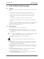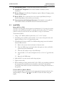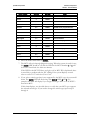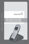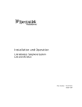
1
Link 150 M3 MCU Installation and Operation Link Wireless Telephone System Part Number: 72-0075-01 Issue F SpectraLink Corporation Installation and Operation Link WTS – Link 150 M3 MCU Notice SpectraLink Corporation has prepared this document for use by SpectraLink personnel and customers. The drawings and specifications contained herein are the property of SpectraLink and shall be neither reproduced in whole or in part without the prior written approval of SpectraLink, nor be implied to grant any license to make, use, or sell equipment manufactured in accordance herewith. SpectraLink reserves the right to make changes in specifications and other information contained in this document without prior notice, and the reader should in all cases consult SpectraLink to determine whether any such changes have been made. The terms and conditions governing the sale of SpectraLink hardware products and the licensing of SpectraLink software consist solely of those set forth in the written contracts between SpectraLink and its customers. No representation or other affirmation of fact contained in this document including but not limited to statements regarding capacity, response-time performance, suitability for use, or performance of products described herein shall be deemed to be a warranty by SpectraLink for any purpose, or give rise to any liability of SpectraLink whatsoever. In no event shall SpectraLink be liable for any incidental, indirect, special, or consequential damages whatsoever (including but not limited to lost profits) arising out of or related to this document, or the information contained in it, even if SpectraLink has been advised, knew, or should have known of the possibility of such damages. Trademark Information SpectraLink The SpectraLink logo LinkPlus Link NetLink SVP Are trademarks and registered trademarks of SpectraLink Corporation. All other trademarks used herein are the property of their respective owners. SpectraLink Corporation 5755 Central Avenue Boulder, CO 80301 303 440 5330 or 800 676 5465 www.spectralink.com Copyright © 1998 to 2006 SpectraLink Corporation. All rights reserved Information in this document is subject to change without notice and does not represent a commitment on the part of SpectraLink Corporation. The software described in this document is furnished under a license and/or copyright and may only be used with the terms of SpectraLink’s software license agreement as found in this manual or at http://www.spectralink.com/consumer/resources/software_updates.jsp. The software may be used only in accordance with the terms of the agreement. No part of this manual, or the software described herein, may be reproduced or transmitted in any form or by any means, electronic or mechanical, including photocopying and recording, for any purpose except for the sole intent to operate the product or without the express written permission of SpectraLink Corporation. PN: 72-0075-01-F.doc Page 2 SpectraLink Corporation Installation and Operation Link WTS – Link 150 M3 MCU WARNING: Changes or modifications to this equipment not approved by SpectraLink Corporation may cause this equipment to not comply with part 15 of the FCC rules and void the user’s authority to operate this equipment. WARNING: SpectraLink products contain no user-serviceable parts inside. Refer servicing to qualified service personnel. IMPORTANT SAFETY INFORMATION Follow these general precautions while installing telephone equipment: • Never install telephone wiring during a lightning storm. • Never install telephone jacks in wet locations unless the jack is specifically designed for wet locations. • Never touch uninsulated telephone wires or terminals unless the telephone line has been disconnected at the network interface. • Use caution when installing or modifying telephone lines • When installing Base Stations outside or in buildings other than the one containing the System Controller, take the following precaution: If wiring for a Base Station exits a building—whether to reach an outdoor Base Station location or to reach a Base Station in another building—the wiring must be protected at both ends by a Quick Clip Fuse from Illinois Tool Works, Linx Division, model number SCP-2X2. The Quick Clip Fuse replaces the bridging clips on the 66 blocks for all four connections to the non-internal Base Station. PN: 72-0075-01-F.doc Page 3 SpectraLink Corporation Installation and Operation Link WTS – Link 150 M3 MCU Table of Contents 1. About This Document 1.1 1.2 1.3 1.4 SpectraLink Corporation Model Numbers Related Documents Customer Support Hotline Icons and Conventions 2. Installation Overview 2.1 Installation Steps and Responsibilities 3. Link Wireless Telephone System Overview 3.1 3.2 System Operation The Front Panel of the Link 150 M3 MCU 4. Site Preparation 4.1 4.2 Required Materials Determine Location of MCU 5. Run Cable for System 5.1 5.2 5.3 5.4 5.5 5.6 5.7 Run Cables to Base Station Locations Pull Cable Terminate Cable at Base Station Locations Prepare Demarc Blocks Install Demarc Blocks Assign and Program Ports Connect Cables from Base Stations and Phone Lines to Demarc Blocks 6. Install Link Wireless Telephone System 6.1 6.2 6.3 6.4 6.5 Survey Site Check Components Install MCUs Install Base Stations Install Outdoor Base Stations 7. Connect and Register Handsets 7.1 7.2 7.3 7.4 7.5 Set Up Diagnostic Modem Register Handsets Unregister Handsets Program Handset Features Test Handsets 6 6 6 6 6 7 8 9 9 11 12 12 12 13 13 13 14 15 18 18 19 23 23 23 24 28 30 31 31 31 32 32 33 8. Site Certification 34 9. System Administration 35 9.1 9.2 9.3 9.4 9.5 9.6 Troubleshoot Error Codes Troubleshoot Handset Features Status LED Codes Replace a Handset Replace an MCU Replace a Base Station 35 35 36 39 40 41 10. Link Wireless Telephone Planning Worksheet 42 11. Base Station Location Worksheet 43 PN: 72-0075-01-F.doc Page 4 SpectraLink Corporation 12. Technical Parameters 12.1 12.2 Select Alternate Spread Spectrum Sequence Change Companding PN: 72-0075-01-F.doc Installation and Operation Link WTS – Link 150 M3 MCU 44 44 45 Page 5 SpectraLink Corporation 1. Installation and Operation Link WTS – Link 150 M3 MCU About This Document This document explains installation and operation of SpectraLink’s Link Wireless Telephone System (Link WTS), using the Link 150 Model 3 (M3) Master Control Unit (MCU). The Link 150 M3 MCU adds wireless service to your existing telephone system. The installation process connects the Link WTS to your telephone system, and activates the Link Wireless Telephones. 1.1 SpectraLink Corporation Model Numbers This document covers the following registered model numbers: SCA416, SCA408, SCA516, SCC408, SCC416, SCD408, SCD416, SCE408, SCE416, SCF4089, SCF416, SCI408, SCI416, SCJ408, SCJ416, SCK408, SCK416, SCL408, SCL416, SCM408, SCM416, SCN408, SCN416, SCO408, SCO416, SCS416, SCT416, SCX416 RCC400, RCO400, RCU100, RCU200, RCU201, MOG400 1.2 Related Documents Link 150 M3 MCU: Installation and Operation (72-0075-01) Link 150 M3 MCU: Quick Reference (72-0075-02) Link 150 M3 MCU: Open Application Interface (OAI) Gateway Installation and Setup (72-0075-07) Link 6020 Wireless Telephone Configuration and Administration (72-1204-00) Installing the Outdoor Base Station (72-0050-01) Available at http://www.spectralink.com/consumer/resources/manuals.jsp. LinkPlus Interface Guide (72-0171-xx where xx indicates a number corresponding to the type of PBX) Available at http://www.spectralink.com/consumer/resources/interface_guides.jsp. 1.3 Customer Support Hotline SpectraLink wants you to have a successful installation. If you have questions please contact the Customer Support Hotline at (800) 775-5330. The hotline is open Monday through Friday, 6 a.m. to 6 p.m. Mountain time. 1.4 Icons and Conventions This manual uses the following icons and conventions. Caution! Follow these instructions carefully to avoid danger. NORM PN: 72-0075-01-F.doc Note these instructions carefully. This typeface indicates a key, label, or button on the MCU or Link Wireless Telephone (handset). Page 6 SpectraLink Corporation 2. Installation and Operation Link WTS – Link 150 M3 MCU Installation Overview Installation has three phases. In most cases, a separate person is responsible for each phase. 1. Site preparation and wire installation: This is usually done by a wire technician or contractor. 2. Installing the SpectraLink system: This is done by SpectraLink or one of our certified distributors. 3. Programming the customer’s telephone system to work with the SpectraLink system: This is usually done by the customer’s system administrator or technician. Because these major steps require some parallel activities, it is important to coordinate the activities among the persons involved. This table lists the installation steps and the person usually responsible for each step. PN: 72-0075-01-F.doc Page 7 SpectraLink Corporation 2.1 9 Installation and Operation Link WTS – Link 150 M3 MCU Installation Steps and Responsibilities Task Description Wire Contractor or Electrician Field Service Engineer Customer Project Mgr/ System Admin Site Preparation Determine location of MCU 9 Run Cable for System Run cable to Base Station locations 9 Pull cable 9 Terminate cable at Base Station locations 9 Prepare and install demarc blocks 9 Assign and program ports Connect cables to demarc blocks 9 9 Install SpectraLink System Survey site and check components 9 Install MCUs 9 Install Base Stations 9 Install outdoor Base Stations 9 Connect and register handsets 9 Set up diagnostic modem 9 Register handsets 9 Program handset features 9 Test handsets 9 Site certification 9 PN: 72-0075-01-F.doc Page 8 SpectraLink Corporation 3. Installation and Operation Link WTS – Link 150 M3 MCU Link Wireless Telephone System Overview Review this section if you are unfamiliar with the features and operation of the Link WTS. 3.1 System Operation The Link WTS is a wireless communication system that offers direct telephone access for incoming and outgoing calls anywhere within a facility. The Link WTS consists of three basic components: the Master Control Unit, the Base Station and Link Wireless Telephones, or handsets. This diagram shows an overview of the system. Components are described below. PBX Analog or Digital Interface Master Control Unit Base Stations OAI Application Gateway Server Link Wireless Telephones The Link Wireless Telephone System Master Control Unit (MCU) Serves as the connecting point, or gateway, between the Base Stations and the existing telephone system. One or more of these boxes (approximately 12” x 3” x 7”) are typically installed in the telephone equipment room and provide connectivity from the telephone system to the Link WTS. Each MCU is hard-wired to one or more Base Stations, which in turn provides the wireless link to each of the Link handsets. The MCU establishes the connection from the telephone line to the appropriate Base Station in order to reach a handset. The MCU supports four Base Stations and up to 16 handsets. Up to four Link 150 M3 MCUs can be linked together for extended coverage area. Chained MCUs support up to 64 handsets maximum. PN: 72-0075-01-F.doc Page 9 SpectraLink Corporation Installation and Operation Link WTS – Link 150 M3 MCU SpectraLink offers an analog MCU that works with telephone systems (CO, PBX or Key Systems) with analog (loop start) ports. We also offer digital MCUs that work with the most common brands of telephone systems’ (PBX or key systems) digital ports. Base Stations Act as a radio transceiver to provide the communications signal between the handset and the MCU. Base Stations are slightly larger than a smoke detector and are typically mounted on the ceiling, in strategic locations throughout the facility. A single Base Station can provide radio coverage for an area of 5,000 to 50,000 square feet depending on building obstructions. Base Stations may be located up to 2,200 cable feet from the MCU. When a handset user makes or receives a call, the handset and Base Station establish a digital radio communication link. As the user moves around the coverage area, calls are “handed off” to the Base Station that is able to provide the best radio signal (typically the closest Base Station). These handoffs involve the handset establishing a communication link with another Base Station and dropping the previous link. Link Wireless Telephones Communicate with the Base Station using digital spread spectrum transmission at 902-928 MHz. Employees can carry handsets to keep in contact as they move throughout the building. The handsets use on-premises wireless technology; they are not cellular or satellite phones. They are connected to the facility’s existing telephone system and, just like wired telephones, can receive calls directly, receive transferred calls, transfer calls to other extensions, and make outside and long distance calls (subject to the restrictions applied in your facility.) PN: 72-0075-01-F.doc Page 10 SpectraLink Corporation 3.2 Installation and Operation Link WTS – Link 150 M3 MCU The Front Panel of the Link 150 M3 MCU The MCU’s front panel contains the connections to the telephone system, switches to control system administration, and status LEDs. 1. STEP Button: Selects a specific line or Base Station during registration process. 2. Mode Switch: Selects the mode of operation for the Link 150 M3 MCU. ADMIN: Administration mode, used to set up system features to match features on the telephone system. NORMAL: Normal mode, used during day-to-day operations. REGISTER: Registration mode, used to add or delete handsets and Base Stations. 3. DEL/ENTER Button: Removes a registered handset from the system. 4. IPC IN Port: Used to connect preceding MCUs in a multi-MCU configuration. 5. IPC OUT Port: Used to connect sequential MCUs in a multi-MCU configuration or to connect to an Open Applications Interface (OAI) Telephony Gateway. 6. ERROR LED: Flashes when the system has detected an error. When flashing, check the STATUS LEDs for an error code. 7. STATUS LEDs: Indicate system error messages and status. Refer to section 9.3 Status LED Codes for more information. 8. LINE LEDs: Indicate the line status of each handset: ringing, in use, or not active. 9. BASE STN LEDs: Indicate the status of each Base Station. 10. CONN A or B: RJ-21 connector to the crossconnect demarc block. Connector B is supplied and used only with four-wire interface. 11. Power Jack: Connects to the AC adapter to supply power to the system. CAUTION: Use only the provided Class II AC Adapter with output 24VDC, 1A. 12. Grounding Lug: For use on the analog interface MCU (SCA-5XX). PN: 72-0075-01-F.doc Page 11 SpectraLink Corporation Installation and Operation Link WTS – Link 150 M3 MCU 4. Site Preparation 4.1 Required Materials The following equipment must be provided by the customer: Outlet Strip Recommended for installations with more than one MCU. This will allow the MCUs to be turned on and off together. Cross-Connect Block Required to connect the telephone switch ports and the Base Stations to the MCU. 25 Pair Cables RJ-21 male at MCU end, required to connect the MCU to the cross-connect blocks. Backboard Space The MCU is designed to be wall mounted to 3/4” plywood securely screwed to the wall. Quick Clip Fuse Required with an RCO410 Outdoor Base Station or when a Base Station is located in a separate building from the Link 150 M3 MCU. Recommended Quick Clip Fuse is available from Illinois Tool Works, Linx Division, Model # SCP-2X2. Base Station Mounting Hardware If the Base Stations will be mounted on finished walls or ceilings, a 4 to 5” long 1/4” bolt, nuts, and washers will be required for each Base Station mounted. 4.2 Determine Location of MCU Each MCU is approximately 2.75” wide, 12.5” high, and 7” deep, and weighs about 5 pounds. The unit is designed to be wall-mounted over 3/4” plywood. • Select a location for the MCU with sufficient backboard space and an available outlet. • The MCU must be within 2,200 feet of the Base Stations. • All digital interface modules must be within 250 feet of the telephone system. • See your telephone system specifications for distance limitations for analog modules. • Since the front panel is used for cabling and as an operator’s console, mount the units so the front panel is accessible. If your system has more than one MCU, the units should be mounted vertically, side by side, physically touching the adjacent unit. Do not stack units on top of one another. Stacked MCUs can cause overheating and failure. PN: 72-0075-01-F.doc Page 12 SpectraLink Corporation Installation and Operation Link WTS – Link 150 M3 MCU 5. Run Cable for System 5.1 Run Cables to Base Station Locations The Base Station locations should be designated on the building floor plans provided to the SpectraLink field service engineer. Base Stations can be mounted easily on raised or acoustical ceiling tiles, or on the wall. Avoid locating Base Stations in high or hard-to-reach places, as this will hinder maintenance, testing and/or repositioning. Wire Specifications The customer’s wire contractor is responsible for adhering to all local codes for wiring. SpectraLink recommends UL-listed wire that conforms to the following specifications for AWG, distance, and number of power pairs required for this installation. Power Pairs Max Cable Feet 22 AWG Max Cable Feet 24 AWG Max Cable Feet 26 AWG 1 1,100 750 470 2 2,200 1,500 940 3 2,200 2,200 1,400 One additional pair is required for data. Attenuation must not exceed 6.8 dB/1,000 feet at 772KHz. Wire that is already installed (spare house cable) can be used when it is available. House cable will usually run from the MDF in the telephone equipment room to intermediate distribution frames (IDFs) spread throughout the facility. Install new wire from the closest IDF to the Base Station. Be sure no bridge taps, multiples, or “Y” connections are created or present. Determine the amount of wire needed to connect the Base Station to the MCU by scaling from a floor plan or a sketch, pacing, measuring, or estimating. Remember to include enough wire to reach the ceiling. 5.2 The wire length between the MCU and each Base Station may not exceed 2,200 cable feet. Install an extra 25 feet of wire at the Base Station to allow for possible relocation. Pull Cable Pull the cable from the MCU location (usually in the telephone equipment room) to the Base Station locations designated on the floor plans. If the cabling exits the building, consult the telephone system manual, the National Electrical Code (NEC), and local codes for instructions on providing lightning and other over-current protection. PN: 72-0075-01-F.doc Page 13 SpectraLink Corporation Installation and Operation Link WTS – Link 150 M3 MCU When cabling an external Base Station or a Base Station with wiring that exits the building, protect all Base Station wiring with the Quick Clip Fuse (Illinois Tool Works, Linx Division, SCP-2X2) before bridging with other Base Station power leads. Run all cable before attaching the RJ-45 connectors to the Base Stations. Label both the demarcation block end and the Base Station end of each wire with the Base Station number using a wire tie marker or other form of marker. Remove bridge taps, multiples, or “Y” connections to the Base Station wires; these will cause data transmission errors. The area above some suspended ceilings is used as an environmental air plenum. The NEC requires that wire installed in plenums be rated for plenum installation. 5.3 Terminate Cable at Base Station Locations After running the wire to the Base Station location, terminate the wire using an RJ45 modular crimp-on plug. Connect the data pair to pins 1 and 2, and the power pair to pins 7 and 8. If the connection uses more than two pair, refer to the table on the following page. To avoid damage to the connectors or crimps, be sure to run the wire to the Base Station before connecting the RJ-45 connectors. 1 8 RJ-45 Modular Cable PN: 72-0075-01-F.doc Page 14 SpectraLink Corporation Installation and Operation Link WTS – Link 150 M3 MCU When wiring the 8-pin connector, use the following table as a guide. 8-pin Modular Connector 5.4 MCU Pin Function Polarity 1 Data 1 Any 2 Data 2 Any 3 Power 3 + 4 Power 2 - 5 Power 2 + 6 Power 3 - 7 Power 1 - 8 Power 1 + Prepare Demarc Blocks The MCU connects to the existing telephone system using RJ-21 connections. An MCU is designed to operate with a specific interface to the telephone system: twowire digital or analog, or four-wire digital. The number of demarcation blocks required for the system depends on the number and type of MCUs installed. Interface Type MCU Part Number Wire Pairs # Blocks Analog POTS SCA-5XX 1 1 Universal Digital Interface (Norstar, Meridian, Comdial, Fujitsu, Inter-Tel, DEFINITY 2-wire, NEC, Rolm, Toshiba) SCU-5XX 1 1 Merlin Legend and DEFINITY 4-wire SCF-5XX 2 2 Mitel (DNIC) SCX-5XX 1 1 Panasonic (Universal 2-wire Auxiliary Digital) SCP-5XX 1 1 Executone (Universal 4-wire Auxiliary Digital) SCB-5XX 2 2 If the wiring between the Link 150 M3 MCU and the telephone system leaves the building, consult your telephone system manual for instructions on providing adequate lightning and other over-current protection. All MCUs (except the analog interface SCA-5XX) are intended only for connection to the isolated side of an on-premises telephone switch. The interfaces are intended to connect to digital telephone switch ports that provide signals of 5Vp-p (max) AC component, and some telephone switches provide a 48 V DC offset. Based on the number and type of interfaces in the system, determine the number of 25-pair cables required to connect line ports and Base Stations to the demarcation blocks. The diagrams which follow provide an overview of the connections. PN: 72-0075-01-F.doc Page 15 SpectraLink Corporation Installation and Operation Link WTS – Link 150 M3 MCU Multiple Power Pairs Some sites may prefer to wire Base Stations to a separate demarc block in order to split out power pairs. Dedicated Line for Diagnostic Modem The Link 150 M3 MCU can be accessed remotely using an internal modem. To use the modem for remote access, a dedicated dial-in line must be provided. On digital interface systems this line must be terminated as a digital extension to the MCU. Two-wire Analog or Digital Interface The wiring diagram below shows the connections required for a two-wire analog or digital interface. A To PBX Telephone Ports Pair 1-16 Pair 17 Unused Pair 18-19 Data Pair 20-23 Pair 24 & 25 Unused To Base Stations Power Pairs Base Stn. 1-4 Data Pairs Base Stn. 1-4 Two-wire Analog or Digital Connection PN: 72-0075-01-F.doc Page 16 SpectraLink Corporation Installation and Operation Link WTS – Link 150 M3 MCU Four-wire Digital Interface The wiring diagram below shows the connections required for a four-wire interface . Each MCU of this type requires two demarcation blocks which will be wired as indicated. B A Receive (RX) To PBX Telephone Ports Pair 1-16 Pair 17-25 Unused To PBX Transmit (TX) From PBX Telephone Ports Pair 1-16 Pair 17 - Unused Power Pairs 18-19 To Base Stations Base Stn. 1-4 Data Pairs 20-23 Base Stn.1-4 Pair 24 & 25 Unused Four-wire Digital Connection PN: 72-0075-01-F.doc Page 17 SpectraLink Corporation 5.5 Installation and Operation Link WTS – Link 150 M3 MCU Install Demarc Blocks The demarcation blocks used to connect the telephone system and Base Stations to the MCU should be installed on a typical telephone facility backboard. A 1/2” or 3/4” thick board mounted on the wall near the MCU is typical. Although this manual uses 66 blocks as examples, any standard cross-connect blocks are acceptable. When cabling an external Base Station or a Base Station with wiring that exits the building, protect all Base Station wiring with the Quick Clip Fuse (Illinois Tool Works, Linx Division, SCP-2X2) before bridging with other Base Station power leads. If the cabling between the MCU and the telephone system leaves the building, consult the telephone system manual, the NEC, and local codes for instructions on providing lightning and other over-current protection. 5.6 Assign and Program Ports The wire contractor should inform the system administrator which port numbers have been designated for the handsets and the remote diagnostics modem line. The system administrator must assign extension numbers to the handsets and plan the functions (trunk access, toll restrictions, system features, ringing options, etc.) to be programmed for the handsets. This programming will be done after the handsets are registered, but will be faster if it is planned in advance by verifying the parameters and features on the current telephone system and wired phones. For details, refer to the for the type of PBX in use at your location. PN: 72-0075-01-F.doc Page 18 SpectraLink Corporation 5.7 Installation and Operation Link WTS – Link 150 M3 MCU Connect Cables from Base Stations and Phone Lines to Demarc Blocks Two-pair twisted cable from Base Stations installed throughout the facility converge at the demarc block or backboard. Each MCU can support four Base Stations and up to 16 handsets. The Base Station and Link Wireless Telephone cables are punched down onto the demarc/cross-connect blocks as shown in the demarc block diagrams below. Refer also to the diagrams in section 5.4 Prepare Demarc Blocks and section 6.3 Install MCUs. Photocopy the and provided in this manual as needed. Use the forms to track the Base Stations and handset port assignments connected to each MCU. As the SpectraLink field service engineer makes each Base Station or handset connection, fill in the information on the form to identify the position of the Base Station or handset (the building and floor number, for example) and a detailed description of the location (perhaps a room number). A copy of this form should be posted near the cross-connect block. Up to four Base Stations can be connected on a single MCU. Each Base Station uses two pair, one for data and one for power. When cabling an external Base Station or a Base Station with wiring that exits the building, protect all Base Station wiring with fuse protection. One method is to use a Quick Clip Fuse (Illinois Tool Works, Linx Division, SCP-2X2) to provide protection from external wiring. If the wiring between the MCU and the telephone system leaves the building, consult the telephone system manual, the NEC, and local codes for instructions on providing lightning and other over-current protection. PN: 72-0075-01-F.doc Page 19 SpectraLink Corporation Installation and Operation Link WTS – Link 150 M3 MCU Two-wire Analog or Digital Demarc Block The demarc block for the two-wire analog or digital interface should be wired as follows. LINE1 LINE 2 LINE 3 LINE 4 LINE 5 LINE 6 LINE 7 Telephone Ports LINE 8 LINE 9 LINE 10 LINE 11 LINE 12 LINE 13 LINE 14 LINE 15 LINE 16 tip ring tip ring tip ring tip ring tip ring tip ring tip ring tip ring tip ring tip ring tip ring tip ring tip ring tip ring tip ring tip ring 25 PAIR MALE CONNECTOR CABLE TO MCU CONNECTOR A UNUSED Base Station Power Pairs 1&2 3&4 1 Base Station Data Pairs 2 3 4 UNUSED Two-wire Connector PN: 72-0075-01-F.doc Page 20 SpectraLink Corporation Installation and Operation Link WTS – Link 150 M3 MCU Four-wire Digital Demarc Block The four-wire digital interface (future release) requires two demarc blocks, one to Connector A and one to Connector B on the MCU. They should be wired as follows. tip ring tip ring tip ring tip ring tip ring tip ring tip ring tip ring tip ring tip ring tip ring tip ring tip ring tip ring tip ring tip ring Line 1 TX Line 2 TX Line 3 TX Line 4 TX Line 5 TX Line 6 TX Line7 TX Telephone Ports Note: TX denotes data transmitted from the telephone system to the Link150 Line 8 TX Line 9 TX Line 10 TX Line 11 TX Line 12 TX Line 13 TX Line 14 TX Line 15 TX Line 16 TX 25 PAIR MALE CONNECTOR CABLE TO MCU CONNECTOR A UNUSED Base Station Power Pairs 1, & 2 3&4 1 Base Station Data Pairs 2 3 4 Unused Four-wire Connector A PN: 72-0075-01-F.doc Page 21 SpectraLink Corporation Installation and Operation Link WTS – Link 150 M3 MCU Line 1 RX Line 2 RX Line 3 RX Line 4 RX Line 5 RX Line 6 RX Line 7 RX Telephone Ports Note: RX denotes data received by the telephone system from Link 150 Line 8 RX Line 9 RX Line 10 RX Line 11 RX Line 12 RX Line 13 RX Line 14 RX Line 15 RX Line 16 RX tip ring tip ring tip ring tip ring tip ring tip ring tip ring tip ring tip ring tip ring tip ring tip ring tip ring tip ring tip ring tip ring 25 PAIR MALE CONNECTOR CABLE TO MCU CONNECTOR B Unused Pairs DO NOT USE Four-wire Connector B PN: 72-0075-01-F.doc Page 22 SpectraLink Corporation Installation and Operation Link WTS – Link 150 M3 MCU 6. Install Link Wireless Telephone System 6.1 Survey Site Check the site to be sure pre-installation work has been completed correctly. This includes: • Location chosen for the MCU is adequate, and power is available. • Wiring to Base Station locations has been pulled and correctly terminated. • Phone lines for the Link Wireless Telephones are installed and properly terminated. • Dedicated line is available for remote access to diagnostic modem. • Telephone system administrator is on-site to program the existing telephone system. If the work has not been completed, the SpectraLink field service engineer can leave the site and reschedule the installation when the items have been completed or corrected, or assist in preparing the site. 6.2 Check Components The following items should be at the installation site. Link 150 M3 Master Control Unit Depending on the size of your system, there may be up to four MCUs, which will be chained together to extend the coverage area. The Link WTS MUST contain only Link 150 M3 MCUs. Link 150 Model 2 MCUs or Model 1 MCUs cannot be used in an M3 system. AC Adapter Supplies power to the Link 150 M3 MCU. Use only the provided Class II AC Adapter with output 24VDC, 1A. IPC Cable Each MCU is shipped with one inter-processor communication (IPC) cable to carry signals between Link 150 M3 MCU units. It is used only when multiple MCUs are chained together. Base Stations SpectraLink Part Number RCC 400/410 or RCO 400/410 (for outdoor use). Your system may have up to four Base Stations for each MCU shipped. Base Station Mounting Hardware A ceiling clip and plastic bolt used to attach each Base Station to the T-bar ceiling tile grid. MCU Mounting Hardware Four #8 x 3/4” panhead wood screws and star washers, used to mount the MCU to the wall. PN: 72-0075-01-F.doc Page 23 SpectraLink Corporation Installation and Operation Link WTS – Link 150 M3 MCU ESD Bonding Straps To provide static protection for the MCU. Link Wireless Telephones The correct number of handsets for this installation. Battery Chargers Link Wireless Telephones require a Battery Charging system, usually one per handset. Battery Packs The system may have one or more spare Battery Pack per handset, depending on the needs at your location. Documentation and Training Information This includes a user guide for each handset and the CD which contains all referenced documents. 6.3 Install MCUs Mount MCUs to Wall The MCUs are designed to be mounted on a backboard of 3/4” plywood, securely fastened to the wall. Mount the MCUs vertically, side by side, using 2.75” spacing center-to-center for each unit. Do not stack MCUs on top of one another. To mount the MCUs: 1. Using a 1/8” drill bit, drill four pilot holes, on 2” x 12.1” centers. 2. If installing only one MCU, insert the #8 x 3/4” screws in the pilot holes and tighten, leaving a 1/8 to 1/4” gap from the wall. 3. If installing more than one MCU, the ESD bonding strap(s) must be installed between adjacent units: 3.1 Remove the screws from the bottom of adjacent units. 3.2 Place the ESD strap over the pilot holes that span two units, and hold it against the plywood backboard. 3.3 Place the star washer on top of the ESD strap. 3.4 Insert the #8 x 3/4” screw and tighten to leave 1/8 to 1/4” gap from the wall. 3.5 Repeat for all ESD straps. 4. Slide the MCU over the screws until it drops in place. 5. Tighten screws fully. 6. When installing an analog interface MCU (SCA-5XX), the grounding terminal in the rear panel of each unit must be electrically connected to earth ground. Consult the NEC and local codes for instructions on making the connection to the ground. Connect MCU to Demarc Blocks Connect the male RJ-21 connector from the appropriate demarcation block to the designated RJ-21 connector (A or B) on each MCU. Secure the cables using the keeper. PN: 72-0075-01-F.doc Page 24 SpectraLink Corporation Installation and Operation Link WTS – Link 150 M3 MCU Connect Multi-Unit Systems Use the following procedure to connect multiple MCUs. 1. Mount the MCUs side by side. 5555 2. Connect the IPC cable from the OUT port of the first unit to the IN port of the adjacent unit. Repeat until all units are connected, as shown in the following illustration. STEP STEP ADMIN STEP ADMIN STEP ADMIN ADMIN NORMAL NORMAL NORMAL NORMAL REGISTER REGISTER REGISTER REGISTER DEL / ENTER DEL / ENTER DEL / ENTER DEL / ENTER IPC IN IPC IN IPC IN IPC IN IPC OUT IPC OUT IPC OUT IPC OUT CONN CONN S T A T U S B CONN S T A T U S B L I N E S CONN S T A T U S B L I N E S L I N E S L I N E S CONN CONN CONN CONN A A A A B A S E S T N S B A S E S T A T U S B S T N S B A S E S T N S B A S E S T N S PWR PWR PWR PWR ! ! ! ! Multi-Unit Link 150 M3 MCUs PN: 72-0075-01-F.doc No IPC cable is connected to the IN port of the first unit. An Open Applications Interface (OAI) Telephony Gateway may be connected to the OUT port of the last unit. Page 25 SpectraLink Corporation Installation and Operation Link WTS – Link 150 M3 MCU Connect Power 1. Connect the power plug from the AC adapter to the jack labeled PWR on the MCU. Use only the provided Class II AC Adapter with output 24VDC, 1A. For installations with more than one MCU, use an outlet strip with a built-in power switch. This allows the MCUs to be turned on and off together. 2. Plug the AC adapter into a 110VAC outlet or switch on the outlet strip to apply power to the MCU. Set Switch Interface Type The following steps explain how to assign a switch interface type to the MCU. This procedure must be done in on each MCU. 1. Power on the MCU with the mode switch in the NORMAL position. Because the MCU does not have a switch type assigned, it will alarm (the ERROR LED will flash along with STATUS LEDs 1, 2, 3, 4, and 5). This should take less than 2 minutes. 2. Power off the MCU. 3. Move the mode switch to ADMIN and power on the MCU. Within 15 seconds, STATUS LEDs 2 and 4 will light. 4. Press the STEP button three times. STATUS LEDs 1, 2, and 4 must be lit. LINE LEDs 1 through 8 (indicating an unconfigured MCU) should also be lit. If any other combination of LINE LEDs is lit, then a switch type has already been selected. Go to step 5 to pick the desired switch type. 5. Press the DEL/ENTER button to select the correct switch interface type. With each press of the DEL/ENTER button, a different series of LINE LEDs will be lit. Continue to press DEL/ENTER until the correct LINE LEDs are lit. Use the following list to select the desired switch interface. PN: 72-0075-01-F.doc Page 26 SpectraLink Corporation Switch Interface Installation and Operation Link WTS – Link 150 M3 MCU Line LEDs MCU Type Analog 1 SCA5xx Comdial 3 SCU5xx DEFINITY – Two-wire 1, 4 SCU5xx DEFINITY – Four-wire 1, 5 SCF5xx Four-wire Interface. Executone 2, 5 SCB5xx The SCB will only support Executone. Fujitsu 2, 4 SCU5xx Inter-Tel 2, 3, 4 SCU5xx Meridian 1, 2 SCU5xx Merlin Legend 1, 3 SCF5xx Four-wire Interface. Mitel 1, 2, 3 SCX5xx The SCX will only support Mitel. NEC 1, 2, 4 SCU5xx Norstar 2 SCU5xx Panasonic 5 SCP5xx Siemens / Rolm 4 SCU5xx 2, 3 SCU5xx Toshiba Unconfigured Notes The SCA will only support Analog. The SCX will only support Panasonic. 1 through 8 6. Move the mode switch back to NORMAL. 7. The MCU will cycle through diagnostic testing. When the system is ready for use, the ERROR LED should be off, and the LED for the MCU Number (1 to 4) will be lit. This should take less than two minutes. If the LED for the MCU ID does not light, or if an MCU ID is duplicated, there is most likely a problem with the IPC cabling. If the system displays an error refer to section 9.1 Troubleshoot Error Codes. 8. If you select a switch type that is not supported by the MCU type, the system will alarm. The ERROR LED will flash along with STATUS LEDs 4 and 5. For example, this alarm will display if you assign switch type NEC to an SCB-5XX – Executone MCU. If this alarm displays, use the table above to verify that your MCU type supports the selected switch type. If you need to change the switch type, repeat steps 2 through 6. PN: 72-0075-01-F.doc Page 27 SpectraLink Corporation 6.4 Installation and Operation Link WTS – Link 150 M3 MCU Install Base Stations Be sure the Base Station is positioned clear of anything that might damage it. The Base Station should be well above head height, away from doors and other objects that might strike it, and away from areas open to the elements or possible water leaks. Check your location for other radio antenna devices and place the Base Stations to avoid interference. Leave enough slack wire (approximately 25 feet) to account for possible future Base Station moves. Mount Base Stations on Dropped Tile Ceilings A ceiling clip and plastic bolt are supplied to install Base Stations on the drop ceiling rails (T-bars) used to support acoustical tile. The plastic bolt screws into the top of the Base Station, then snaps into the ceiling clip which has been attached to the rails that hold the acoustical tile. The fastener is designed for use on 15/16” wide rails. 1. Attach the metal fastener to the rail (T-bar) supporting the dropped ceiling by rotating it into position until it snaps into the locked position. 2. Screw the plastic bolt to the 1/4” x 20 captive nut into the top of the Base Station. 3. Slide the bolt into the exposed prongs of the metal clip until it snaps into position. 4. When properly attached, the Base Station should sit almost flush against the ceiling, and be tightly attached to the clip and T-bar grid work. 5. Once the Base Station is anchored to the fastener, lift the acoustical tile and plug the RJ-45 8-pin modular plug into the connector on the top of the Base Station. • The LED will blink red and green as the system software downloads to the Base Station and the Base Station is tested. • When the LED blinks amber, the system is ready for operation. • When the LED blinks green, a telephone has established a radio link with that Base Station. • If the LED turns solid red, there should be an error message on the MCU’s STATUS LEDs. Refer to section 9.1 Troubleshoot Error Codes. PN: 72-0075-01-F.doc Page 28 SpectraLink Corporation Installation and Operation Link WTS – Link 150 M3 MCU Mount Base Stations On Finished Ceilings If your site does not have a dropped tile ceiling, the Base Station can be mounted to a finished ceiling or wall with a 4 to 5” long 1/4” –20 TPI plastic or nylon screw or bolt (such as a lag screw). The customer’s wire contractor is responsible for this installation. 1. Drill two holes approximately 1” apart. Make the holes large enough to accommodate the RJ-45 connector and a bolt to secure the Base Station. 2. Insert a wide washer above the ceiling, then screw the bolt into the beam or ceiling. 3. Insert three nuts on the bolt, then screw the Base Station into the bolt, being careful not to insert the bolt more than 1/3”, five full turns, into the Base Station. 4. If the ceiling is open with I-beams or pipe construction, mount the Base Station with I-beam clamps or pipe clamps. PN: 72-0075-01-F.doc Page 29 SpectraLink Corporation 6.5 Installation and Operation Link WTS – Link 150 M3 MCU Install Outdoor Base Stations Outdoor Base Stations are equipped with a protective enclosure, designed to be mounted to a wall or pole. After the enclosure is mounted, the Base Station is inserted in the enclosure and connected. Only RCO Base Stations can be used outdoors. The customer’s wire contractor is responsible for wiring and mounting the outdoor Base Station enclosure. The contractor is responsible for supplying screws, brackets, and other appropriate hardware. Wire and Connect Outdoor Base Stations If the wiring for a Base Station exits a building—whether to reach an outdoor Base Station location or to reach a Base Station in another building—it should be equipped with primary protection according to the NEC and/or local codes. Wiring that exits the building must also be fuse protected at both ends. For example, use a Quick Clip Fuse from Illinois Tool Works, Linx Division, model number SCP-2X2. Insert the Quick Clip fuses in place of bridging clips on a 66 block for the non-internal Base Station circuits. 1. Mount the outdoor Base Station enclosure to a wall or pole. The enclosure should be attached at the highest point available that will provide central coverage for the outdoor area. 2. Insert the Base Station cable through the compression fitting and tighten the fitting. 3. Wire the Base Station connector just as you wired the RJ-45 connectors for the indoor Base Stations. 4. Place the Base Station inside the enclosure with the part number label facing the back of the enclosure. 5. Screw the protective cover onto the Base Station enclosure. PN: 72-0075-01-F.doc Page 30 SpectraLink Corporation Installation and Operation Link WTS – Link 150 M3 MCU 7. Connect and Register Handsets 7.1 Set Up Diagnostic Modem Each MCU has an internal modem feature that allows SpectraLink technicians to dial into the system for troubleshooting and maintenance. The modem is enabled on Line 1 when no handset is registered to Line 1. When enabled, the modem will autoanswer an incoming call to that line. This internal modem uses proprietary communication software. You cannot use commercial software packages to access this software. If you have a multiple MCU system, you only need to enable one modem line, on Line 1 of MCU 1. Line 1 positions on the other MCUs can be used for handsets. To set up the diagnostic modem: 1. Connect an analog Direct Inward Dial (DID) line to Analog Interface MCUs (SCA-5XX) or a digital DID line to Digital Interface MCUs. 2. Move the mode switch to the REGISTER position. The LED for Line 1 should be off, indicating that no handset is registered to Line 1. If the LED is on then a handset is registered to the line. Refer to section 7.3 Unregister Handsets. 3. Dial the number associated with the DID line. After one or two rings, you should hear the high-pitched modem answer tone. 7.2 Register Handsets Before a handset can be used it must be registered to a line on one of the MCUs. While handsets are being registered, the system will continue normal operation. Use the filled out by the system administrator to be sure you are correctly assigning each handset to its port and extension number. All lines are unregistered when shipped from the factory. However, if you are replacing a failed MCU you may not need to register the handsets. Refer to section 9 System Administration for details. Line 1 MCU 1 may be skipped to allow for remote access through the diagnostic modem. Each MCU supports eight simultaneous conversations. To optimize performance and reduce the possibility of call blocking, distribute the handsets evenly across all MCUs. To register a handset to your system do the following: 1. Be sure all unregistered handsets are powered off and that there is a Base Station plugged in and within range of the handsets to be registered. 2. Move the mode switch to the REGISTER position. (If your system has more than one MCU, be sure to move the switch only on the correct MCU.) The LED which indicates the Box ID (1 through 4) may change. This is normal and is not an error. PN: 72-0075-01-F.doc Page 31 SpectraLink Corporation Installation and Operation Link WTS – Link 150 M3 MCU The LINE indicator LEDs now show the registration status of each line. • If the LED is on, a handset is registered to the line. • If the LED is off, no handset is registered to the line. 3. Press the STEP button until the LED for the line to be registered flashes. • If the LED is flashing, that line is selected. A flash with the LED mainly off indicates no handset registered; a flash with the LED mainly on indicates a handset is registered to the selected line. • Initially Line 2 will flash. This is because Line 1 is usually set up as the remote access diagnostic modem. To register a handset to Line 1, press the STEP button until Line 1 flashes. • If the desired line already has a handset registered to it, follow the procedure outlined below to unregister the handset, then return to this step. 4. Turn on the handset to be registered by holding down the PWR key until the handset beeps twice. After a few seconds, the line indicator LED on the MCU will shine solid red. Once the handset is registered, the LED for the next line begins to flash. 5. To assign the extension number, hold down the FCN key until Volume Level displays. Press the # > key until EXTENSION displays on the handset. Press 0, then enter the correct extension number. Press END when finished. 6. Repeat steps 3 through 5 for all handsets to be registered. 7. When all handsets are registered, return the mode switch to the NORMAL position. 7.3 Unregister Handsets If the desired line already has a handset registered to it, follow this procedure to unregister the handset. 1. Move the mode switch on the MCU to the REGISTER position. If your system has more than one MCU, be sure to move the switch on the correct MCU. The LINE indicator LEDs now show which lines have handsets registered. 2. Use the STEP button to select the line to be unregistered. The LINE indicator LED for a line that has a handset registered to it will flash with the LED mainly on. 3. Press the DEL/ENTER button. The LINE indicator LED for the selected line will be off with a short on flash 4. Register the new handset or return the mode switch to the NORMAL position. 7.4 Program Handset Features PBX and Key Systems provide users with special features such as hold, transfer, conference, camp on, and speed dial. These features can be accessed via the handset, but the telephone system or Link 150 M3 MCU must be programmed to allow access to these features from the handset. For information on programming the switch to operate with the handsets, refer to for your PBX PN: 72-0075-01-F.doc Page 32 SpectraLink Corporation 7.5 Installation and Operation Link WTS – Link 150 M3 MCU • If the Link 150 M3 MCU is connected to your telephone system via analog lines, refer to the for analog systems. • If your Link 150 M3 MCU is connected to a digital key telephone system or PBX, refer to the document that deals specifically with your brand of telephone system. Test Handsets Verify proper registration and operation of each handset by performing the following steps. 1. Press the START key on each handset. The extension number should clear and you should hear dial tone. On some digital systems, depending on how the telephone system is programmed, you may have to select a line to get dial tone. 2. Place a call to each handset to verify ring, answer, clear transmit, and clear receive audio. 3. Verify all programmed features on each handset. 4. Press the END key. The LINE indicator should turn off. PN: 72-0075-01-F.doc Page 33 SpectraLink Corporation 8. Installation and Operation Link WTS – Link 150 M3 MCU Site Certification The SpectraLink field service engineer should not leave the site before contacting SpectraLink to perform remote install verification. Contact a SpectraLink engineer on the Customer Support Hotline at (800) 775-5330. The hours of operation are 6 a.m. to 6 p.m. Mountain time, Monday through Friday. The engineer will connect with the diagnostic modem, verify calling functions, and listen while you perform a walk test. The walk test will require you to walk the inside perimeter of the coverage area. If all Base Stations are running, note any areas with heavy static or clarity problems and report them to a SpectraLink Engineer. The installation is not complete until these certification steps have been performed. Do not hand out Link Wireless Telephones at a site that has not been certified. PN: 72-0075-01-F.doc Page 34 SpectraLink Corporation Installation and Operation Link WTS – Link 150 M3 MCU 9. System Administration 9.1 Troubleshoot Error Codes When an alarm is detected, the ERROR LED will light and the MCU’s STATUS LEDs will display an alarm code. If the error code refers to a Base Station problem, the Base Stn LED will indicate which Base Station has the problem. If more than one Base Stn LED is on, the error code refers to the lowest numbered Base Station with an error. Use the STEP button to select another Base Station to display its error code. For additional assistance in troubleshooting your system, please contact the SpectraLink Customer Support Hotline at (800) 775-5330. The hotline is open Monday through Friday, 6 a.m. to 6 p.m. Mountain time. 9.2 Troubleshoot Handset Features If handset features are not working properly, disconnect the handset from the MCU and plug a wired telephone into the port. The telephone should be the same type as the emulated telephone. Refer to the appropriate section of the LinkPlus Interface Guide for your PBX type. Test the features on the wired telephone. • For analog MCUs, verify that feature access codes and switchhook flash work correctly. • For digital MCUs, verify that features are assigned to the correct keys and are working properly. Refer to the appropriate for button mapping information for the brand of telephone system at your location. PN: 72-0075-01-F.doc Certain four-wire telephones (such as MERLIN LEGEND) use a different connector on the phone than on the back of the MCU. Therefore you may need phone cord or an adapter to perform these tests. Page 35 SpectraLink Corporation 9.3 Installation and Operation Link WTS – Link 150 M3 MCU Status LED Codes STATUS LEDs 12345 Description Action Random Cycling The Link 150 M3 MCU is powering up. Initialization to follow. This is not an error and should change to another code after a minute. 5 Link 150 M3 MCU is initalizing. Code number will change when finished. 1, 2, 3, or 4 MCU identification number. Indicates normal operation when it is on steady. If the same LED is lit on more than one MCU: Check the IPC connections. If the LED is flashing and the ERROR light is on: There is a problem with the MCU indicated by the flashing box ID. The following STATUS LEDs are displayed in combination with the ERROR LED. STATUS LEDs Description Action Assign a switch type to the MCU. See section 6.3 Install 1, 2, 3, 4, 5 MCU has not been configured for switch interface type. MCUs -Set Switch Interface Type for instructions. 1, 3 A Base Station has reported an internal problem. Replace the Base Station. In rare cases a problem with the MCU can cause this error. 2, 3 No communication with one or more Base Stations on this MCU. Check cabling to verify that the Base Station’s cable is plugged into and fully seated in the Base Station port at the back of the MCU and plugged into the Base Station at the other end. If the LED on the Base Station is not lit, check for proper wiring of the 8-pin modular plugs. See section 5.3 Terminate Cable at Base Station Locations. If the cable is over 600 feet long, verify that the extra wire pairs have been connected correctly. If the Base Station LED is flashing red, check for open or shorts on pins 1 and 2 of the cable. If the Base Station has been removed, acknowledge the alarm by moving the mode switch to REGISTER. Press the STEP button until the LED for the removed Base Station is blinking. Press DEL/ENTER, then move the mode switch back to NORMAL. 1, 2, 3 Internal communication problem with the MCU. Replace the MCU. 4 IPC problem. Check IPC cabling by disconnecting and reconnecting the MCUs. Connect the Male RJ-21 connector from the appropriate demarcation block to the designated RJ-21 connector (A or B) on each MCU. Secure cables using the keeper. If the error still occurs try using a different IPC cable. Replace MCU if the problem still occurs. PN: 72-0075-01-F.doc Page 36 SpectraLink Corporation STATUS LEDs Installation and Operation Link WTS – Link 150 M3 MCU Description Action 4, 5 The switch type selected is not supported by this MCU. Verify that the switch type selected is correct. If the type is incorrect, repeat the steps to select a new switch type. See section 6.3 Install MCUs -Set Switch Interface Type 1, 4 The operator is trying to register a handset or place an admin call on an MCU with no phone lines. Return mode switch to the NORMAL position. 2, 4 The MCU was powered on with the mode switch in the wrong position. Turn off the MCU, place the mode switch to the NORMAL position and turn back on. 3, 4 Configurations on a multi-MCU installation do not match in each of the units. Most likely to occur when an MCU was just added to the system. Erase the configuration in the MCU with incorrect configuration definitions (probably the MCU that was just added.) To erase the configuration, refer to section 9.5 Replace an MCU. Note: Do not erase the configurations in all the MCUs. In multiple MCU installations the handset registration information is shared among the MCUs. This allows you to replace an MCU without re-registering all the handsets. 1, 3, 4 REGISTER or ADMIN mode selected on more than one MCU at the same time. Only one mode switch can be in ADMIN or REGISTER at a time. Check the MCUs and take one of them out of REGISTER or ADMIN mode. 2, 3, 4 The MCU was powered on with the mode switch in the wrong position. Turn off the unit, place the mode switch to the NORMAL position and turn back on. 1, 2, 3, 4 Internal problem with the MCU. Contact SpectraLink Customer Service for technical support. 1, 5 The MCU was powered on with the mode switch in the wrong position. Turn off the MCU, place the mode switch in the NORMAL position and turn back on.. A possible Base Station failure has been detected. A Base Station that had previously been heard by another Base Station can no longer be heard. Check to see if the system was powered on with the switch in the wrong position. If not, contact SpectraLink Customer Service. The MCU was powered on with the mode switch in the wrong position. Turn off the MCU, place the mode switch in the NORMAL position and turn back on. One or more of the Base Stations on this unit is disabled because it is located too close to other Base Stations. The ERROR display refers to the LED that is red. If more than one LED is red, it refers to the lowest numbered Base Station. Identify which Base Station has been disabled and move it away from its nearest neighbor Base Station If Mode switch is in ADMIN mode: Adjust the companding mode from Mu law to A law. Refer to section 12.2 Change Companding The MCUs have incompatible versions of software. Contact SpectraLink Customer Service for technical support. 5 3, 5 PN: 72-0075-01-F.doc Page 37 SpectraLink Corporation Installation and Operation Link WTS – Link 150 M3 MCU Handset Status Indicator Messages Indicator Description Action BATT Displays when user is on the handset and the battery charge is low. The user has two minutes to complete the call. Replace the Battery Pack with one that is charged. BATTERY LOW Displays when user is not on the handset and battery charge is low. The handset will ring to alert user to this condition. The handset will not work until the Battery Pack is replaced. Replace the Battery Pack with one that is charged. INTERNAL ERROR Communications error between the handset and the MCU. Have the user turn the handset off, then on again. If the error persists try registering another handset to this port. If the problem persists, contact technical support. NO PBX There is no telephone system port connected to the port associated with this handset, or the telephone system has not yet synchronized the port. This message should disappear when the telephone system ports are wired and programmed correctly. PT UNREGISTERED The handset is not yet registered to an MCU. Register the handset. PN: 72-0075-01-F.doc Page 38 SpectraLink Corporation 9.4 Installation and Operation Link WTS – Link 150 M3 MCU Replace a Handset If a handset breaks or needs to be replaced, the old handset must be deleted and the new handset added. Delete Old Handset 1. Make sure all unregistered handsets are off. If this is not done an unregistered handset may unintentionally register to an available line. 2. Move the mode switch to the REGISTER position on the MCU. 3. Press the STEP button until the LED for the line to be deleted is flashing red. 4. Press the DEL/ENTER button. You can now register a new handset or return the mode switch to the NORMAL position. Register New Handset 1. Make sure all unregistered handsets are off. 2. Move the mode switch to the REGISTER position. 3. Press the STEP button until the desired line to be registered is flashing red. Only unregistered lines can be registered. 4. Press PWR on the handset that needs to be registered. The LED should change to mostly on once the handset is registered. 5. Wait at least three seconds and then press END. 6. Return the mode switch to the NORMAL position. 7. To assign the extension number, hold down the FCN key until Volume Level displays. Press the # > key until EXTENSION displays on the handset. Press 0, then enter the correct extension number. 8. When the handset is turned on, the extension will be displayed. Test the handset by placing a call to each handset to verify that the correct handset rings. PN: 72-0075-01-F.doc Page 39 SpectraLink Corporation 9.5 Installation and Operation Link WTS – Link 150 M3 MCU Replace an MCU When the system has more than one MCU, each MCU contains a complete set of configuration information for the entire system. This includes handset registration information, function definitions, and frequency sequence selection. This Configuration Sharing feature allows a failed MCU in a multi-unit installation to be replaced without having to register the handsets again. To replace a failed MCU, first clear the configuration information on the replacement MCU, then replace the failed MCU. Clear Configuration on Replacement MCU 1. Remove power from the replacement MCU. There should be no IPC cables connected to the IPC ports. 2. Slide the mode switch on the replacement MCU to the ADMIN position. 3. Apply power. 4. Press the STEP button until the STATUS LEDs light 2, 3, and 4 of the replacement MCU. 5. Press the DEL/ENTER button. 6. Remove power from the unit. 7. Slide the mode switch to the NORMAL position. Connect the Replacement MCU 1. Remove the failed MCU from the IPC chain 2. Connect the replacement MCU in the position vacated by the failed MCU. 3. Reconnect the IPC cables for the chain. Double-check that the IN and OUT ports are correctly connected. 4. Apply power to the MCU. 5. After a few moments each MCU in the chain should have a unique box ID number (1 through 4), shown on the STATUS LEDs. If this is not the case, recheck the IPC wiring. 6. If the replacement MCU has STATUS LED 3 and 4 lit, the configuration data has not been successfully shared. Most likely, the replacement MCU was powered up before it was correctly attached to the IPC chain. Repeat the entire replacement procedure. PN: 72-0075-01-F.doc Page 40 SpectraLink Corporation 9.6 Installation and Operation Link WTS – Link 150 M3 MCU Replace a Base Station To replace a Base Station, unplug the existing Base Station and plug in the new Base Station. • The LED will blink red and green as the system software downloads to the Base Station and the Base Station is tested. • When the LED blinks amber, the system is ready for operation. • When the LED blinks green, a handset has established a radio link with that Base Station. • If the LED turns solid red, there should be an error message on the MCU’s STATUS LEDs and the MCU ERROR LED should be lit. PN: 72-0075-01-F.doc Page 41 SpectraLink Corporation Installation and Operation Link WTS – Link 150 M3 MCU 10. Link Wireless Telephone Planning Worksheet Copy and complete this worksheet to keep track of the port numbers, extensions, users, and features assigned to your handsets. MCU ID: _________ Handset # Extension Port ID User Name Feature Notes 1* 2 ** 3 4 5 6 7 8 9 10 11 12 13 14 15 16 PN: 72-0075-01-F.doc *On MCU No. 1: Reserve Port 1 for access to SpectraLink Diagnostic Modem **On MCU No. 1: Port 2 is used for administrative programming (analog system only) Page 42 SpectraLink Corporation Installation and Operation Link WTS – Link 150 M3 MCU 11. Base Station Location Worksheet MCU: ________ Base Station # Location (e.g.: building, floor #, detailed description) Port ID Base Station 1 1 Base Station 2 2 Base Station 3 3 Base Station 4 4 MCU: ________ Base Station # Location (e.g.: building, floor #, detailed description) Port ID Base Station 1 1 Base Station 2 2 Base Station 3 3 Base Station 4 4 MCU: ________ Base Station # Location (e.g.: building, floor #, detailed description) Port ID Base Station 1 1 Base Station 2 2 Base Station 3 3 Base Station 4 4 MCU: ________ Base Station # Location (e.g.: building, floor #, detailed description) Port ID Base Station 1 1 Base Station 2 2 Base Station 3 3 Base Station 4 4 PN: 72-0075-01-F.doc Page 43 SpectraLink Corporation Installation and Operation Link WTS – Link 150 M3 MCU 12. Technical Parameters 12.1 Select Alternate Spread Spectrum Sequence The Link WTS uses spread spectrum radio transmission. Spread spectrum takes a discrete signal, such as a digitized voice conversation, and spreads it over a wide range of frequencies rather than transmitting at a single carrier frequency. The frequency range may need to be adjusted if other wireless devices in your facility, such as data terminals or bar code readers, share the same frequency band. Units shipped from the factory are preset to operate on sequence 1, which spans the entire spectrum from 902MHz to 928MHz. If interference between the Link WTS and other 900MHz radio devices is anticipated or observed, any one of six alternate sequences can be selected. Determine the frequency band of the interfering device, then use the frequency ranges below (given in MHz) to select the best interference avoidance pattern for the situation. Sequence Frequencies Used by SpectraLink 1 902-928 2 902-915 3 902-909 & 921-928 4 914-928 5 902-904 & 909-921 6 904-910 & 920-928 7 908-922 To change a system to an alternate sequence, perform the following steps for each MCU. 1. Wait for any calls in progress to end. Power the system off, then slide the mode switch to the REGISTER position. 2. Power the system on. STATUS LEDs 5 and 1 should be lit, indicating frequency selection mode. One of the LINE LEDs from 1 to 7 will be indicating the current frequency selected for the MCU. 3. Use the STEP button to select the desired new sequence. 4. Press the DEL/ENTER button. The LED indicates the new frequency that has been selected. 5. Return the mode switch to the NORMAL position. 6. Repeat steps 1 through 5 for each MCU of a multi-unit installation. PN: 72-0075-01-F.doc Page 44 SpectraLink Corporation Installation and Operation Link WTS – Link 150 M3 MCU 12.2 Change Companding The factory setting on the Link 150 M3 MCU is compatible with Mu-law companding (signal compression), which is the standard used by most PBXs in North America. Systems outside North America generally use A-law companding. If the PBX companding is incompatible with the MCU’s, the handsets will have distorted or hissing dial tone, and voice will be unintelligible. Before you begin, if the system has more than one MCU, erase the configurations from all MCUs except MCU 1. Refer to section 9.5 Replace an MCU for instructions. To change the default from Mu- to A-law on the Link 150 M3 MCU follow these steps. 1. Power the system off. 2. Slide the mode switch on the first MCU to the ADMIN position. 3. Power the system on. STATUS LEDs 2, 3, and 4 will be solid green. 4. Press the STEP button once. STATUS LEDs 2 and 5 will be lit. 5. If the LED for LINE 1 is lit, the system is set for Mu-law. If the LED for LINE 2 is lit, the system is set for A-law. 6. Press the DEL/ENTER button to toggle between Mu-law and A-law. 7. When the correct LINE LED is lit, return the mode switch to the NORMAL position. PN: 72-0075-01-F.doc Page 45 SpectraLink Corporation Installation and Operation Link WTS – Link 150 M3 MCU Index AC Adapter, 23 A-law, 45 Alternate sequence, 44 Forms Base Station location, 43 Wireless Telephone Planning Worksheet, 42 Attenuation, 13 Frequency, transmission, 44 Base Station, 23 Cabling, 13, 14 Description, 10 Installation, 28 LED, 35 Location form, 43 Outdoor, 30 Outside Wiring, 30 Replacing, 41 Hand-off, 10 Battery Chargers, 24 Cabling Base Station specifications, 13 Base Station, external, 18 Base Station, internal, 13 Demarcation blocks, 18 Exiting the building, 14 Four-wire digital, 17 IPC, 27 Prepare Demarc Blocks, 15 Quick Clip Fuse, 12 RJ-45 modular, 14 Shipped with system, 23 Troubleshooting, 36 Two-wire analog or digital, 16 Hotline, 6 Interface types, Demarc, 15 Interference, frequency, 44 LED Base Station, 35 Codes, 36 Front Panel, 11 Line indicator, 11 Troubleshooting, 35 Link WTS, Overview, 9 Master Control Unit. See MCU MCU Base Station cabling, 13 Connect to Demarc Blocks, 25 Description, 9 Front Panel, 11 Location, 12 Mounting, 24 Multiple, 25 Replacing, 40 Ceiling clip, 23, 28 Mode Switch, 11 Chargers, 24 Modem, 16, 31 Companding, 45 Mounting Hardware, 23 Configuration sharing, 40 Mu-law, 45 Connecting MCU to Telephone System, 15 PBX type, 26 Coverage, 10 Power AC Adapter. See Outlet strip, 12 Power jack, 11 Customer Support Hotline, 6 Demarcation blocks Four-wire digital, 21 Installing, 18 Two-wire analog or digital, 20 Programming, 18 Quick Clip Fuse, 12 Diagnostic Modem, 16 Register Wireless Telephone, 31 Error Codes, 35 Remote Access via modem, 16 ESD bonding strap, 24 Replacing Base Station, 41 MCU, 40 Wireless Telephone, 39 Extension numbers, 39 Batteries, 24 PN: 72-0075-01-F.doc Page 46 SpectraLink Corporation Installation and Operation Link WTS – Link 150 M3 MCU Site Certification, 34 Unregister Wireless Telephone, 32 Site Preparation, 12 Walk test, 34 Site Survey, 23 Wireless Telephone Description, 10 Planning Worksheet, 42 Program, 33 Register, 31 Replacing, 39 Test, 33 Unregister, 32 Spread Spectrum Sequence, 44 STEP Button, 11 Switch type, 26 Ports, 16 Troubleshooting, 35 PN: 72-0075-01-F.doc Page 47