1
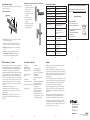
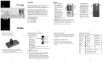
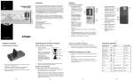
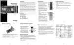
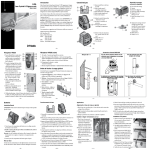
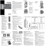
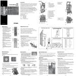
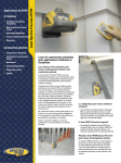
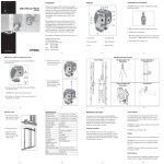
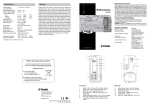
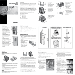
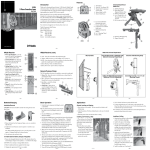
HR150 Receiver
User Guide
•
Introduction
Receiver
Thank you for choosing the Spectra Precision® Laser Receiver HR150
from the Trimble® family of precision instruments. The HR150 is a
battery-operated laser receiver that detects a rotating laser beam and
indicates its position relative to the beam using LEDs.
Before using the receiver, be sure to read this user guide carefully.
Included in it is information about setting up, using, and maintaining
the receiver. Also included in this manual are CAUTIONS and Notes.
Each of these words represents a level
of danger or concern. A CAUTION indicates a hazard or unsafe
practice that could result in minor injury or property damage.
A Note indicates important information unrelated to safety.
Your comments and suggestions are welcome; please contact us at:
Trimble Construction Division
5475 Kellenburger Road
Dayton, Ohio 45424-1099 U.S.A.
Phone: (937) 245-5600
(800) 538-7800
FAX:
(937) 233-9004
Internet: www.trimble.com
Features and Functions
1. Power/Audio Button—is a
multi-functional button that
4
turns on/off the receiver and
5
audio function.
3
2. Marking Notches (both
2
2
sides)—align with the
on-grade portion of the
photocell and are used to
1
mark elevation readings.
The marking notches are
6
50mm (2 inches) from the
top of the receiver.
3. LEDs (front and back)—
show the position of the
receiver relative to the laser beam (high, on-grade, or low), and
indicate power and low-battery status.
4. Level Bubble—is used to make sure that the receiver is level.
5. Photocell—detects the laser beam when it strikes the receiver.
6. Audio Port—is the opening the sound comes out of.
–2–
–3–
07. Clamp-Tab Recess—is the
area that the general-purpose
clamp’s release tab fits into.
08. Label—shows the serial
number and bar code.
09. Magnet—holds the receiver
on a wall molding, cross-T,
runner, etc.
10. Battery Housing—holds two
AA alkaline or Ni-Cd
batteries.
11. Battery Door—holds the
batteries securely in place.
12. Neck Cord Holder—allows a
neck cord to be attached to
the receiver.
9
8
7
10
11
12
www.trimble.com
How to Use the Receiver
Learning the Receiver Functions
Installing/Removing the Batteries
Turning On/Off the Receiver
1. Press the power/audio button to turn on the receiver.
Note: When the receiver is initially turned on, all LEDs and the
audio signal turn on for one second (diagnostic mode).
Note: The on-grade LED flashes once every two seconds to show
that the receiver is on.
2. Press and hold the power/audio button for two seconds to turn off
the receiver.
Note: When the receiver is being turned off, all the LEDs and the
audio signal quickly turn on for one second.
1. Release the battery door using your fingers, a coin, or a
screwdriver. Open the door.
2. Install/Remove the 2 AA batteries noting the positive (+) and
negative (–) diagram on the bottom of the battery housing.
3. Close the battery door and latch it shut.
Selecting the Audio Function
The receiver always starts up with the audio mode active.
1. Press the power/audio button repeatedly to turn on/off the
audio function.
Note: If the audio function is on, the receiver beeps quickly when
the receiver is above the laser beam, slowly when below it, and
continuously when centered in the laser beam or on grade.
–4–
Using the Receiver with a Laser
1. Press the power/audio button to turn on the receiver.
2. Position the receiver so that its photocell faces the laser.
3. Move the receiver up/down until the LEDs show an on-grade
reading.
Note: The top/bottom red LEDs flash when the receiver is above
or below the laser beam. The green LED flashes when the receiver
is on grade.
High
On Grade
Low Battery
LED/Audio Information
LED/Audio Indication Function
Audio Output
Green LED: flashes
once every two seconds
Receiver is on
N/A
Top red LED: flashing
High
Fast beeping tone
Green LED: flashing
On-grade
Continuous tone
Bottom red LED:
flashing
Low
Slow beeping tone
Both red LEDs:
flashing in sequence
Low battery
N/A
Speaker beep
Audio on
3 beeps
Beam location
Single beep
Low
Power/Audio Button
Audio Port
–5–
–6–
–7–
–8–
General-Purpose Clamp
The C61 general-purpose clamp allows the receiver to be attached to a
survey rod or wooden pole.
Features and Functions
1
2
3
4
Attaching the Receiver to the Survey Rod or Wooden Pole
1. Slide the general purpose
clamp into the receiver until it
“clicks” into position.
2. Turn the jaws screw
counterclockwise to open the
clamp’s jaws.
3. Slide the survey rod or
wooden pole between the
clamp’s jaws.
4. Turn the jaws screw clockwise
to hold the general-purpose
clamp securely in place.
Receiver Specifications
LED Channels
3
Capture Height
50 mm (2 in.)
Acceptance Angle
90°
On-Grade Sensitivity
Medium: 3.00 mm (1/8 in.)
Power Source
Two 1.5-V batteries (type LR6/AA)
–9–
Low Battery Indicator
Red LEDs flash in sequence
Automatic Shutoff
30 minutes after last laser detection
or push-button actuation
Spectral Sensitivity
Operates with red visible and
infrared rotating lasers with
wavelength between 610 and
900 nm
Marking Notch
50 mm (2 in.) below top of
receiver, on both sides
Operating Temperature
–20 °C to +50 °C
(–4 °F to +122 °F)
Storage Temperature
–40 °C to +70 °C
(–40 °F to +158 °F)
Weight
0.3 kg (.75 lb)
Dimensions (H x W x D)
13.6 x 5.0 x 2.8 cm
(5.37 x 2.00 x 1.11 in.)
– 10 –
Declaration of Conformity
Warranty
This receiver has been tested and found to comply with the limits for
a Class B digital device for radio noise for digital apparatus set out
in the Radio Interference Regulations of the Canadian Department
of Communication, and is pursuant to part 15 of the Federal
Communication Commission (FCC) rules. These limits are designed
to provide reasonable protection against harmful interference in a
residential installation. This receiver generates radio frequency. If it’s
not used in accordance with the instructions, it may cause harmful
interference to radio or television reception. Such interference can be
determined by turning the receiver off and on. You are encouraged
to try eliminating the interference by one or more of the following
measures:
• Reorient or relocate the receiving antenna.
• Increase the separation between the laser and the receiver.
For more information, consult your dealer or an experience radio/
television technician.
CAUTION: Changes or modifications to the receiver that are
not expressly approved by Trimble could void authority to use the
equipment.
Application of
Council Directive(s):
Manufacturer’s Name:
Manufacturer’s Address:
Trimble warrants the receiver to be free of defects in material and
workmanship for a period of one year.
Trimble or its authorized service center will repair or replace, at its
option, any defective part for which notice has been given during the
warranty period. If required, travel and per diem expenses to and from
the place where repairs are made will be charged to the customer at
the prevailing rates.
Customers should send the product to Trimble Navigation Ltd. or the
nearest authorized service center for warranty repairs, freight prepaid.
In countries with Trimble subsidiary service centers, the repaired
product will be returned to the customer, freight prepaid.
Any evidence of negligent, abnormal use, accident, or any attempt
to repair the product by other than factory-authorized personnel
using Trimble certified or recommended parts, automatically voids
the warranty.
The foregoing states the entire liability of Trimble regarding
the purchase and use of its equipment. Trimble will not be held
responsible for any consequential loss or damage of any kind.
This warranty is in lieu of all other warranties, except as set forth
above, including any implied warranty merchantability of fitness for
a particular purpose, are hereby disclaimed. This warranty is in lieu
of all other warranties, expressed or implied.
European Representative
Address:
Model Number:
Conformance to Directive(s):
Equipment Type/Environment:
Product Standards:
Trimble Navigation Ltd.
5475 Kellenburger Road
Dayton, Ohio 45424-1099 U.S.A.
Trimble GmbH
Am Prime Parc 11
65479 Raunheim, Germany
HR150
EC Directive 89/336/EEC using
EN55022 and EN50082-1
ITE/residential, commercial
& light industrial
Product meets the limit B
and methods of EN55022
Product meets the levels and
methods of IEC 801-2, 8 kV air,
4 kV contact IEC 801-3, 3 V/m 26
to 1000 MHz 80%, @ 1 kHz
Recycling in Europe
To recycle Trimble WEEE,
call: +31 497 53 2430, and
ask for the “WEEE associate,” or
mail a request for recycling instructions to:
Trimble Europe BV
c/o Menlo Worldwide Logistics
Meerheide 45
5521 DZ Eersel, NL
– 11 –
EMC Declaration of Conformity
89/336/EEC
For product recycling instructions and more information,
please go to: www.trimble.com/environment/summary.html
Battery Life @ 20 °C (68 °F) Alkaline: 70+ hours
5
1. Release Tab—allows the receiver to be locked onto or released
from the general-purpose clamp.
2. Jaws—close/open so that the general-purpose clamp can be
attached to or released from a survey rod or wooden pole.
3. Reading Edge—aligns with the receiver’s on-grade marking
notches.
4. Jaws Screw—controls the closing/opening of the jaws.
5. Circular Bubble Screw Holes—are where the optional
1277-6251S grade rod circular bubble kit is mounted.
Notice to Our European Union Customers
– 12 –
Trimble Construction Division
5475 Kellenburger Road
Dayton, Ohio 45424-1099
U.S.A.
+1-937-245-5600 Phone
www.trimble.com
– 13 –
– 14 –
– 15 –
© 2006, Trimble Navigation Limited. All rights reserved.
Reorder PN 1277-7571 (11/06)