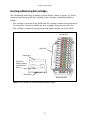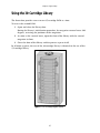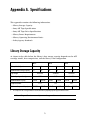
1
P.N. 90870782 Revision E
Notices
Notices
Except as expressly stated herein, Spectra Logic Corporation makes available its products and associated
documentation on an “as is” basis, without warranty of any kind, either expressed or implied, including but
not limited to the implied warranties or conditions of merchantability and fitness for a particular purpose.
In no event shall Spectra Logic be liable for any loss of profits, loss of business, loss of use of data,
interruption of business, or for indirect, special, incidental, or consequential damages of any kind, even if
Spectra Logic has been advised of the possibility of such damages arising from any defect or error.
Information furnished in this manual is believed to be accurate and reliable. However, no responsibility
is assumed by Spectra Logic for its use. Because of continuing research and development, Spectra Logic
may revise this publication from time to time without notice, and reserves the right to change any
product specification at any time without notice.
Some products or services mentioned in this manual are provided by companies other than Spectra
Logic. Inquiries about one or more of these products or services should be sent directly to the company
in question. These brand or product names, registered trademarks, and trademarks are property of their
respective owners. These trademarks may be registered in this country, other countries, or both.
Spectra 2K Library User Guide
Copyright © 2003 Spectra Logic Corporation. All rights reserved.
2
Notices
License
You have acquired Spectra Logic® products that include software owned by or licensed by Spectra Logic from
one or more software licensors (Software Suppliers). Such software products, as well as associated media,
printed materials and “online” or electronic documentation (Software) are protected by copyright laws and
international copyright treaties, as well as other intellectual property laws and treaties. The Software is
licensed, not sold.
If you do not agree to this End User License Agreement (EULA), do not use the Spectra Logic product.
Instead, promptly contact Spectra Logic for instruction on return of the product for a refund. Any use of
the Software, including but not limited to use of the product, will constitute your agreement to this EULA
(or ratification of any previous consent).
GRANT OF LICENSE. The Software is licensed, not sold. This EULA grants you the following rights to the
Software:
• You may use the Software only on the Product with which it was sold.
• Not fault tolerant. The Software is not fault tolerant. Spectra Logic has independently determined how
to use the Software in the product, and suppliers have relied upon Spectra Logic to conduct sufficient
testing to determine that the Software is suitable for such use.
• No warranties for this software. The Software is provided “as is” and with all faults. The entire risk as
to satisfactory quality, performance, accuracy, and effort (including lack of negligence) is with you.
Also, there is no warranty against interference with your enjoyment of the Software or against
infringement. If you have received any warranties regarding Software, those warranties do not
originate from, and are not binding on, Software Suppliers.
• Note on Java support. The Software may contain support for programs written in Java. Java technology
is not fault tolerant and is not designed, manufactured, or intended for use of resale as online control
equipment in hazardous environments requiring fail-safe performance, such as the operation of
nuclear facilities, aircraft navigation or communication systems, air traffic control, direct life support
machines, or weapons systems, in which the failure of Java technology could lead directly to death,
personal injury, or severe physical or environmental damage.
• No liability for certain damages. Except as prohibited by law, Software Suppliers shall have no liability
for any indirect, special, consequential or incidental, damages arising from or in connection with the
use or performance of the Software. This limitation shall apply even if any remedy fails of its essential
purpose. In no event shall Software Suppliers, individually, be liable for any amount in excess of U. S.
two hundred fifty dollars (U.S. $250.00).
• Limitations on reverse engineering, decompilation, and disassemly. You may not reverse engineer,
decompile, or disassemble the Software, except and only to the extent that such activity is expressly
permitted by applicable law notwithstanding this limitation.
• Software transfer allowed with restrictions. You may permanently transfer rights under this EULA only
as part of a permanent sale or transfer of the Product, and only if the recipient agrees to this EULA. If
the Software is an upgrade, any transfer must also include all prior versions of the Software.
• Export restrictions. Export of the Software from the United States is regulated by Export
Administration Regulations (EAR, 15 CFR 730-744) of the U. S. Commerce Department, Bureau of
Export Administration. You agree to comply with the EAR in the export of re-export of the Software:
(i) to any country to which the U.S. has embargoed or restricted the export of goods or services,
which as of May 1999 include, but are not necessarily limited to Cuba, Iran, Iraq, Libya, North Korea,
Sudan, Syria, and the Federal Republic of Yugoslavia (including Serbia, but not Montenegro), or to any
national or any such country, wherever located, who intends to transit or transport the Software back
to such country; (ii) to any person or entity who you know or have reason to know will utilize the
Software or portion thereof in the design, development or production of nuclear, chemical, or
biological weapons; or (iii) to any person or entity who has been prohibited from participating in U.S.
export transactions by any federal agency of the U.S. government. You warrant and represent that
neither the BXA nor any other U.S. federal agency has suspended, revoked or denied your export
privileges. For additional information see: http://www.microsoft.com/exporting/.
3
Notices
Warnings and Cautions
AC Power
Warning: Risk of electrical shock. To remove AC power from the library,
unplug the power cord from the power inlet. There are no user
serviceable parts within the library.
High Voltage
Warning: The Spectra 2K library contains high-voltage components that can
cause injury or death. Only qualified electricians should replace
or install high-voltage components.
Robotics
Warning: Serious injury can result if hair, clothing or appendages are
caught in the library’s robotics. Keep hair, clothing and
appendages clear of moving parts. Do not override any of the
safety features built into the library.
Tapes
Caution: Use only the data cartridges approved for use with the drives in
this library. Improper data cartridges can cause damage to the
drives, library and cartridges.
4
Contents
Notices . . . . . . . . . . . . . . . . . . . . . . . . . . . . . . . . . . . . . . . . . . . . . . . . . . . . . . . . . 2
License . . . . . . . . . . . . . . . . . . . . . . . . . . . . . . . . . . . . . . . . . . . . . . . . . . . . . . . . . 3
Warnings and Cautions . . . . . . . . . . . . . . . . . . . . . . . . . . . . . . . . . . . . . . . . . . . . . 4
Chapter 1. Introduction
9
About TreeFrog® Architecture . . . . . . . . . . . . . . . . . . . . . . . . . . . . . . . . . . . . . . . . 9
About This Guide . . . . . . . . . . . . . . . . . . . . . . . . . . . . . . . . . . . . . . . . . . . . . . . . . . 9
Getting Started . . . . . . . . . . . . . . . . . . . . . . . . . . . . . . . . . . . . . . . . . . . . . . . . . . . . 9
Conventions Used . . . . . . . . . . . . . . . . . . . . . . . . . . . . . . . . . . . . . . . . . . . . . . . . 10
How to Contact Spectra Logic Corporation
. . . . . . . . . . . . . . . . . . . . . . . . . . . . . 10
Chapter 2. Installing the Library
11
Unpacking the Library . . . . . . . . . . . . . . . . . . . . . . . . . . . . . . . . . . . . . . . . . . . . . 11
Attaching to the Host Computer . . . . . . . . . . . . . . . . . . . . . . . . . . . . . . . . . . . . . . 14
Attaching More than One SCSI Device . . . . . . . . . . . . . . . . . . . . . . . . . . . . . . . . . 18
Powering On the Library and Host Computer . . . . . . . . . . . . . . . . . . . . . . . . . . . . 20
Inserting Media . . . . . . . . . . . . . . . . . . . . . . . . . . . . . . . . . . . . . . . . . . . . . . . . . . 21
Installing the Data Cartridge Magazine(s) . . . . . . . . . . . . . . . . . . . . . . . . . . . . . . . 21
Using Horizontal and Rack Mounted Libraries . . . . . . . . . . . . . . . . . . . . . . . . . . . 24
Chapter 3. Configuring the Library
25
Changing the Library’s Configuration . . . . . . . . . . . . . . . . . . . . . . . . . . . . . . . . . . 25
Custom Configurations . . . . . . . . . . . . . . . . . . . . . . . . . . . . . . . . . . . . . . . . . . . . . 27
5
Contents
Chapter 4. Using the Library
31
Getting to Know the Library . . . . . . . . . . . . . . . . . . . . . . . . . . . . . . . . . . . . . . . . . 31
About AIT Bar Code Labels . . . . . . . . . . . . . . . . . . . . . . . . . . . . . . . . . . . . . . . . . 35
Attaching Bar Code Labels . . . . . . . . . . . . . . . . . . . . . . . . . . . . . . . . . . . . . . . . . . 36
Using AIT Data Cartridges . . . . . . . . . . . . . . . . . . . . . . . . . . . . . . . . . . . . . . . . . . 36
Using the Data Cartridge Magazine . . . . . . . . . . . . . . . . . . . . . . . . . . . . . . . . . . . . 39
Getting Information from the Picker’s LED . . . . . . . . . . . . . . . . . . . . . . . . . . . . . . 40
Using the 30-Cartridge Library . . . . . . . . . . . . . . . . . . . . . . . . . . . . . . . . . . . . . . . 41
Chapter 5. Using the AIT Tape Drives
43
Getting to Know the AIT Tape Drive . . . . . . . . . . . . . . . . . . . . . . . . . . . . . . . . . . 43
Getting Information From the Drive LEDs . . . . . . . . . . . . . . . . . . . . . . . . . . . . . . . 44
Maintaining the AIT Tape Drive . . . . . . . . . . . . . . . . . . . . . . . . . . . . . . . . . . . . . . 46
Chapter 6. Library Stacker Mode
49
Stacker Mode Overview . . . . . . . . . . . . . . . . . . . . . . . . . . . . . . . . . . . . . . . . . . . . 49
Arranging Cartridges in the DCM . . . . . . . . . . . . . . . . . . . . . . . . . . . . . . . . . . . . . 51
Controlling the Library Stacker . . . . . . . . . . . . . . . . . . . . . . . . . . . . . . . . . . . . . . . 52
Using the Library in Stacker Mode . . . . . . . . . . . . . . . . . . . . . . . . . . . . . . . . . . . . 52
Chapter 7. Maintenance, Troubleshooting, and Repairs
55
Maintaining the Library . . . . . . . . . . . . . . . . . . . . . . . . . . . . . . . . . . . . . . . . . . . . 55
Updating Library Robotics Firmware . . . . . . . . . . . . . . . . . . . . . . . . . . . . . . . . . . . 60
Troubleshooting the Library . . . . . . . . . . . . . . . . . . . . . . . . . . . . . . . . . . . . . . . . . 61
Purchasing Additional Library Accessories . . . . . . . . . . . . . . . . . . . . . . . . . . . . . . 64
Purchasing Bar Code Labels . . . . . . . . . . . . . . . . . . . . . . . . . . . . . . . . . . . . . . . . . 65
Shipping Information . . . . . . . . . . . . . . . . . . . . . . . . . . . . . . . . . . . . . . . . . . . . . . 66
Spectra Logic Repair Policies . . . . . . . . . . . . . . . . . . . . . . . . . . . . . . . . . . . . . . . . 67
Contacting Spectra Logic . . . . . . . . . . . . . . . . . . . . . . . . . . . . . . . . . . . . . . . . . . . 71
6
Contents
Appendix A. Specifications
73
Library Storage Capacity . . . . . . . . . . . . . . . . . . . . . . . . . . . . . . . . . . . . . . . . . . . . 73
Sony AIT Tape Specifications . . . . . . . . . . . . . . . . . . . . . . . . . . . . . . . . . . . . . . . . 74
Sony AIT Tape Drive Specifications . . . . . . . . . . . . . . . . . . . . . . . . . . . . . . . . . . . 75
Library Power Requirements . . . . . . . . . . . . . . . . . . . . . . . . . . . . . . . . . . . . . . . . 76
Power Cable . . . . . . . . . . . . . . . . . . . . . . . . . . . . . . . . . . . . . . . . . . . . . . . . . . . . 76
Library Operating Environment Limits . . . . . . . . . . . . . . . . . . . . . . . . . . . . . . . . . 77
Safety Agency Standards . . . . . . . . . . . . . . . . . . . . . . . . . . . . . . . . . . . . . . . . . . . 78
Appendix B. SCSI Cable and Terminator Requirements
79
SCSI Cable Requirements . . . . . . . . . . . . . . . . . . . . . . . . . . . . . . . . . . . . . . . . . . . 79
SCSI Terminator Requirements . . . . . . . . . . . . . . . . . . . . . . . . . . . . . . . . . . . . . . . 81
Appendix C. Regulatory Notices
83
FCC Notice . . . . . . . . . . . . . . . . . . . . . . . . . . . . . . . . . . . . . . . . . . . . . . . . . . . . . 83
Japan . . . . . . . . . . . . . . . . . . . . . . . . . . . . . . . . . . . . . . . . . . . . . . . . . . . . . . . . . . 83
Taiwan . . . . . . . . . . . . . . . . . . . . . . . . . . . . . . . . . . . . . . . . . . . . . . . . . . . . . . . . 83
EU Declaration of Conformity . . . . . . . . . . . . . . . . . . . . . . . . . . . . . . . . . . . . . . . . 84
Index
87
7
Contents
8
1 Introduction
About TreeFrog® Architecture
The Spectra 2K library uses TreeFrog architecture for robotic tape libraries developed
by Spectra Logic. TreeFrog architecture can be configured with 15 or 30 cartridge slots
and one or two tape drives. In addition, TreeFrog architecture supports SCSI-2
interfaces—both low-voltage differential/single-ended (LVD/SE) and differential. The
cornerstones of TreeFrog architecture are the integrated robotic picker and the
uni-body robotic chassis.
About This Guide
This guide is intended to be read by the owners of the Spectra 2K library. It covers the
installation and operation of the library, as well as troubleshooting information. For the
latest up-to-date information please go to www.spectralogic.com, and view the latest
Spectra 2K Library User Guide. Also available are these related publications:
Related Publications
• Spectra 2K Library Release Notes provides last-minute information about the Spectra
2K library.
• Spectra 2K Library Developer Guide provides SCSI reference material and other
references useful to application developers.
Getting Started
If your library is already installed and configured, begin with Chapter 4 Using the
Library. To install and configure the library from the beginning, read all of the
chapters of this guide in sequence.
9
Chapter 1. Introduction
Conventions Used
This guide uses special conventions to highlight notes, cautions, and warnings. These
conventions are explained below:
Note: Read Notes for additional information or suggestions about the
topic or procedure being discussed.
Caution: Read Cautions to learn ways to avoid damaging the library, tape
drives or other equipment.
Warning: Read Warnings to learn ways to avoid personal injury.
How to Contact Spectra Logic Corporation
United States Office
European Office
Mailing Address Spectra Logic Corporation
1700 N 55th Street
Boulder CO 80301
USA
Phone
(800) 833-1132 or (303) 449-6400
Mailing Address Spectra Logic Europe Limited
Hampden House
Monument Business Park
Warpsgrove Lane
Chalgrove Oxon
UK-OX44 7RW
Fax
(303) 939-8844
Phone
+44 (0) 870 112 2150
Fax
+44 (0) 870 112 2175
10
2 Installing the Library
To install the library, complete the steps outlined in these sections:
•Unpacking the Library
•Attaching to the Host Computer
•Attaching More than One SCSI Device
•Powering On the Library and Host Computer
•Inserting Media
•Installing the Data Cartridge Magazine(s)
•Using Horizontal and Rack Mounted Libraries
Unpacking the Library
Save the original packing material. If the need arises, return the library with the
original packaging materials.
Note: Failure to return the library in its original packaging risks voiding
the library’s warranty.
To unpack the library, first note how the library is packed into its box (Figure 2-1),
then proceed to the step-by-step instructions that follow.
11
Chapter 2. Installing the Library
Figure 2-1 Unpacking the library.
1. Remove the cardboard tray from the top of the box. This tray contains the
accessories for the library (see Library Accessories on page 13).
2. Remove the top piece of foam protecting the library.
3. Lift the library out of the box.
Warning: Take care when lifting the library. It weighs approximately 30
pounds.
4. Remove the plastic overwrap, taking care not to scratch the paint on the library’s
exterior.
5. With the library still sitting up on its end, use the library door key to open the
library door.
6. Remove the plastic and foam protecting the robotic picker (Figure 2-2 and
Figure 2-3).
12
Chapter 2. Installing the Library
Caution: Take care when removing these pieces not to damage the door
sensor cable (the white cable that runs along the right side of the
library).
Remove plastic.
Remove foam
Figure 2-2 Remove the plastic that protects the
robotic picker from moving while shipping.
Figure 2-3 Remove the foam that protects the
robotic picker from moving while shipping.
Note: Remember to save all packaging materials in the event that you
need to ship the library at a later date.
Library Accessories
The library comes with the following accessories:
•One 120-volt AC power cord
(in packages shipped within the United States and Canada)
•One or two data cartridge magazine(s)
•Two keys for the library’s front door
•One small screwdriver, for configuring settings on the back of the library
•One Quick Install Guide
•One CD-ROM with library documentation.
13
Chapter 2. Installing the Library
Attaching to the Host Computer
Follow this procedure to connect the library as the only unit on a SCSI bus. To attach
more than one SCSI device, read Attaching More than One SCSI Device on page 18, as
well as the documentation for the other device(s) on the bus.
About the SCSI IDs and the SCSI Bus
The library communicates with the host computer through a system of cables and
connectors called the Small Computer System Interface (SCSI). The library uses an
extremely fast version of SCSI called Ultra Wide SCSI, which can connect up to 16
devices in a series. Each SCSI device requires a unique SCSI ID. The library contains
either two or three SCSI devices:
•Library robotics
•Drive 1
•Drive 2 (optional)
The library requires one SCSI ID for the library robotics and one SCSI ID per drive for
a maximum of three possible SCSI IDs. The factory SCSI ID settings work correctly for
most SCSI bus configurations.
Note: Don’t change the default settings for the library’s SCSI IDs unless
necessary; see Attaching More than One SCSI Device on page 18.
LVD/SE or Differential SCSI Interface
The library is available with either an LVD/SE or differential SCSI interface. You will
need to purchase the appropriate terminator for that interface—the LVD/SE library
requires an active, multimode LVD/SE terminator, and the differential unit requires a
differential terminator.
If you are not sure about the interface for your library, you can determine it in one of
two ways:
1. Locate the SCSI interface label between the two SCSI connectors on the back
panel of the library (Figure 2-4).
14
Chapter 2. Installing the Library
2. The library interface can be identified by its part number sticker, also located on
the back panel of the library (Figure 2-4).
• An LVD/SE library has a W in the position directly following the second
hyphen of the part number: 9087####-#-W#
• The differential library has a D in the position directly following the second
hyphen: 9087####-#-D#
Part
number
SCSI interface
Figure 2-4 The part number sticker indicates the type of SCSI interface.
15
Chapter 2. Installing the Library
LVD/SE SCSI Bus
The LVD/SE library operates in either single-ended or low-voltage-differential SCSI
mode, depending on the type of bus that is attached.
Note: The entire bus (including host bus adapter, devices, and
termination) must be LVD to operate in LVD mode. Attaching any
single-ended SCSI device to an LVD bus renders the entire bus
(and all attached devices) subject to the maximum specification
requirements for single-ended SCSI (including maximum cable
lengths).
The LVD/SE terminator should function in either mode. To check the mode in which
your library is operating, look at the library terminator and the terminator’s lightemitting diode (LED). The top of the terminator lists the color of the LED for each
mode.
SCSI specifications for LVD and single-ended modes are shown in this table:
SCSI Specifications
LVD Mode
Single-Ended Mode
SCSI Bus Width
16 bits
16 bits
Maximum Bus Speed
80 MB/sec
40 MB/sec
Maximum Bus Cable Lengths
12 metersa
1.5 metersa
a
Maximum cable length requirements include the internal cabling for each device. The library contains 60 centimeters (24 inches) of
cabling inside the library.
Attaching the SCSI Cable
Note: The library requires a minimum of two SCSI IDs on the SCSI bus.
To attach the library to the host computer:
1. Turn off the computer and library.
2. Determine the correct specifications for the SCSI cable as described in SCSI
Cable Requirements on page 79.
3. Attach the SCSI cable to the connector on the back of the library.
4. Attach the other end of the SCSI cable to the host computer.
16
Chapter 2. Installing the Library
5. Determine the correct specifications for the SCSI terminator as described in SCSI
Terminator Requirements on page 81. Attach a SCSI terminator to the free SCSI
connector on the library, as shown in Figure 2-5.
Caution: The SCSI bus must be terminated at both ends or unexpected
errors may result. Make sure that the SCSI adapter in the host
computer has the appropriate termination enabled.
Computer
Library
SCSI cable
SCSI cable
Terminator
Figure 2-5 Connect the library to the host computer with the SCSI cable. Connect a SCSI terminator
to the library (as necessary).
6. To attach additional devices to the SCSI bus, continue with Attaching More than
One SCSI Device and complete any further procedures as necessary.
The SCSI card BIOS should display the following information:
SCSI ID: 1
SCSI ID: 2
SCSI ID: 3
Sony SDX-300C or Sony SDX-500C or Sony SDX-700C
Sony SDX-300C or Sony SDX-500C or Sony SDX-700C
(if Drive 2 is installed)
Spectra 215
17
Chapter 2. Installing the Library
Attaching More than One SCSI Device
To attach more than one device to the same SCSI bus, review the following sections:
•Verifying the SCSI Bus Requirements, below.
•Changing SCSI IDs as Necessary on page 19.
Verifying the SCSI Bus Requirements
To attach more than one device to a SCSI bus, confirm that the following requirements
have been met:
•Make sure that the total length of the SCSI bus is as short as possible to minimize
the potential for communication errors, such as cross-talk.
•Make sure that the total length of the SCSI bus, including cabling inside the library
and all other devices, does not exceed the maximum length specified in Appendix
B. SCSI Cable and Terminator Requirements.
•The SCSI IDs of all devices must be unique; no two devices can share the same SCSI
ID. To change the SCSI IDs for the library and drives, review Changing SCSI IDs as
Necessary on page 19.
Note: An incorrectly configured SCSI bus causes most problems
experienced while installing the library. Eliminate SCSI bus
problems early by taking the time to configure the bus correctly
the first time.
18
Chapter 2. Installing the Library
Changing SCSI IDs as Necessary
Note: Do not change the default SCSI ID settings for the library or the
drives unless they are set to the same value(s) already in use by
other devices on the same SCSI bus or unless required by your
software.
To change the SCSI IDs:
1. After you have confirmed the need to modify the
SCSI IDs of the library and/or the drives, power off
the library, the host computer, and any other
device on the SCSI bus.
2. Locate the SCSI ID switches on the back panel of
the library (see Rear Panel Components on page
34).
3. Determine the correct settings for the SCSI ID
switches. Each tape drive and the library require a
unique SCSI ID number.
4. Using the small screwdriver included with the
library, set the SCSI IDs of the drives and the
library to the correct values.
5. Verify that the SCSI IDs do not match the ID of any
other device on the SCSI bus including the SCSI ID
for the host computer’s controller card (usually 7).
6. Verify the unique settings of every device on the
SCSI bus.
Figure 2-6 Use a small
screwdriver to set the switch to the
correct SCSI ID (default setting
shown). Do not turn the library
configuration (Config) switch.
Caution: Incorrectly set SCSI IDs will cause malfunctions.
See Chapter 3 Configuring the Library for further explanation of the use of the
configuration switch.
19
Chapter 2. Installing the Library
Powering On the Library and Host Computer
After correctly connecting the library to the host computer, perform the steps
described in the following sections.
Powering On the Library
Power on the library before powering on the host computer and take note of the
library’s initialization routine:
•The picker moves along the length of the library, checking the data cartridge
magazine (DCM) and tape drive(s) for data cartridges.
•The picker records the cartridge locations in the library firmware.
•The bar code reader records bar code information in the library firmware.
•The picker parks at the bottom of the library in front of Drive 1; its LED displays a
green light.
If you experience problems, see Troubleshooting the Library on page 61.
Powering On the Host Computer
The host computer initializes the library and establishes connectivity between the SCSI
devices at power up. The default settings for the SCSI IDs and device identification
settings are:
SCSI ID: 1
SCSI ID: 2
SCSI ID: 3
Sony SDX-300C or Sony SDX-500C or Sony SDX-700C
Sony SDX-300C or Sony SDX-500C or Sony SDX-700C
(If Drive 2 is installed)
Spectra 215
Note: Most UNIX operating systems create device driver files for the
library as soon as the library and drives have been detected. Refer
to your operating system documentation for information about the
naming and location of device files.
For information about common problems communicating over the SCSI bus, see
Troubleshooting SCSI Problems on page 63.
To change the SCSI IDs, see Changing SCSI IDs as Necessary on page 19.
20
Chapter 2. Installing the Library
Inserting Media
The simplest way to insert media into your library is to load the DCM(s) with tapes
before installing the DCM(s) in the library. To do this, insert tapes one at a time into
the individual slots in the DCM, with the clear plastic window of the cartridges facing
away from the drives.
Note: For additional information regarding inserting media into the
DCM, see Figure 4-5 on page 37.
Installing the Data Cartridge Magazine(s)
A library may be configured to hold 15 cartridges (one DCM) or to hold 30 cartridges
(two DCMs). To install your first or only DCM, proceed as follows:
1. Use the library door key to open the library door.
2. Remove the DCM from its protective packaging.
21
Chapter 2. Installing the Library
Position the DCM so that the holes on the side of the DCM line up with the pegs
inside the library (Figure 2-7).
Holes
Figure 2-7 Properly align the DCM for insertion in the library.
Note: For additional information regarding the correct positioning of the
DCM, see Figure 4-5 on page 37.
3. Holding the DCM in one hand, push it firmly into its place behind the robotic
picker. You will hear it snap into place when it fits correctly.
4. Close and lock the library door.
To Install the Second (Optional) DCM:
1. Remove the DCM from its protective packaging.
2. Connect power to the library and turn it on; the library will initialize.
You will see the picker move and then stop to rest at the bottom of the library.
You will then see the rotation of the DCM, so that the first DCM installed now
faces the back of the library.
3. After the rotation completes, use the library door key to open the library door
and stop the initialization process.
4. Position the second DCM upright, as you did the first, and firmly press it into its
place. You will hear it snap into place when it fits correctly.
22
Chapter 2. Installing the Library
5. Close and lock the library door.
Reading and Writing Data to Tape
Before performing store and restore operations with the library, use your backup
software to test library/host communications. Refer to your backup software
documentation for instructions on specific testing procedures.
If you experience difficulty with any one of the procedures above, you may need to
change the library’s configuration as discussed in the next chapter.
23
Chapter 2. Installing the Library
Using Horizontal and Rack Mounted Libraries
Every Spectra 2K library can be operated in either a vertical or horizontal position.
In vertical position, the drives should be located on the bottom of the unit.
With the library in the horizontal position, the key lock is at the top and the hinges of
the door are at the bottom.
Operating the library in the horizontal position requires a Horizontal Conversion Kit.
To operate the library in a rack mount configuration requires a Horizontal Rack Mount
Kit. See Purchasing Additional Library Accessories on page 64 for information about
ordering these kits from Spectra Logic.
Figure 2-8 Positioned correctly, the horizontal (or rack mounted) library door opens downward.
24
3 Configuring the Library
The Spectra 2K library is compatible with most operating systems. This chapter
discusses:
• Changing the Library’s Configuration
• Custom Configurations
Changing the Library’s Configuration
The library is configured through the configuration switch located on the back panel.
Figure 3-1 The rear panel of the library with a larger view of the configuration switch.
About the Configuration Switch
The configuration switch determines:
• Emulation mode for the robotics
• Emulation mode for the AIT tape drives
25
Chapter 3. Configuring the Library
The default position of the configuration switch (0) identifies the library and tape
drives with the following information:
• Library Inquiry (or Name): Spectra 215
• Drive Manufacturer: Sony
• Drive Model: SDX-300C or SDX-500C or SDX-700C
• Drive DIP Switch: 0
These values, returned by the SCSI INQUIRY command, inform the host computer how
to communicate with the library and tape drives. Some operating systems require
custom configurations in order to communicate with the library. Customizing the
library’s configuration is the subject of the remaining sections in this chapter.
For the latest information about operating system specific installation procedures, see
your operating system documentation, or see the Server Preparation Document for
Spectra Logic Libraries, an on-line document located on the Spectra Logic Web site at
www.spectralogic.com/support/support_docs.cfm
Note: All configuration settings are controlled through the configuration
switch on the back panel of the library. The Configuration Switch
Settings table on page 28 summarizes the available configuration
switch settings.
26
Chapter 3. Configuring the Library
Determine Your Configuration
The Spectra 2K library will run successfully with the attached server or host computer
running most operating systems, and secondary configuration switch changes are
usually not required.
If the computer attached to the library is running one of the following, secondary
configuration switch changes are required.
Operating System
Computer Description
Switch Value
HPUX 9.x, HPUX 10.x, HPUX 11.x
HP 9000 Model 700/800 with GSC controller (HSC Bus)
A
HPUX 9.x, HPUX 10.x, HPUX 11.x
HP 9000 Model 800 with 28696A SCSI Controller (HP-PB Bus)
D
For more information about preparing your server for the Spectra 2K library, see the
Server Preparation Document for Spectra Logic Libraries, an on-line document located
on the Spectra Logic Web site at: www.spectralogic.com/support/support_docs.cfm
Custom Configurations
The library has two types of SCSI devices: the robotic tape picker and the AIT tape
drive(s). The configuration switch configures these devices to emulate, other devices.
Because one switch changes the behavior of both the robot and the drives, the
configuration switch may need to be set twice:
• Set the configuration switch once to change the library robotics emulation.
• Set the configuration switch a second time to change the AIT drive emulation.
Note: The most recent configuration always overrides previous
configurations. Values listed as no change retain the previous
setting.
27
Chapter 3. Configuring the Library
Before setting the emulation mode for the library robotics or tape drives, find the
setting you want to use in the table below.
Response to the Inquiry Command
Drive
Model
Drive DIP
Switch
Settinga
Emulation Mode
Switch Setting
Library Inquiry
Drive
Manufacturer
Default—
random access
0
Spectra 215
Sony
SDX-300C
SDX-500C
SDX-700C
0
Tape stacker mode—Drive
1 only,
no random access robotics
commands
1
No changeb
No changeb
No changeb
No changeb
Spectra 10000 library
emulation
2
Spectra 10000
No changeb
No changeb
No changeb
Exabyte EXB 210 library
emulation
3
Exabyte EXB-210
Exabyte
EXB-8900
No changeb
HP 9000 Model 700/800
(GSC Controller) emulation
A
No changeb
Hewlett Packard
C-1533A
13
Quantum DLT-7000 drive
emulation
B
No changeb
Quantum
DLT-7000
No changeb
Custom (AIT-2 only)
C
No changeb
Sony
SDX-300C
No changeb
StorageTek 9490 drive
emulation
D
No changeb
STK
9490
No changeb
Spectra 4000 library emulation
E
Spectra 4000
No change
No change
No changeb
User-defined emulation
F
Use the serial cable to change these settings
a. The Drive DIP Switch (default 0) determines the drive emulation and is set electronically by the configuration switch.
b. Values listed "No change" retain the last setting; it may be necessary to set the configuration switch a second time.
28
Chapter 3. Configuring the Library
Changing Configurations
To change the emulation mode for the library robotics or tape drives:
1. Power off the library.
2. With a small screwdriver, set the configuration switch to the value that
corresponds with the desired emulation mode.
3. With the library door closed, power on the library.
As the library changes its configuration, the robotic tape picker pauses in front
of the data cartridge magazine and the LED blinks amber and green. When
complete, the picker parks in front of the drive(s).
4. Check the new configuration by using your backup software, or by checking
that the host computer reflects the SCSI ID inquiry string changes.
The SCSI card BIOS should display the following information:
SCSI ID: <ID #>
SCSI ID: <ID #>
SCSI ID: <ID #>
<DRIVE MODEL>
<DRIVE MODEL>
<LIBRARY INQUIRY>
Make sure that the ID numbers, drive models, and library setting appear as you
wanted them set.
5. Repeat Step 1 through Step 4 for other emulations as necessary.
Changing Configurations More than Once
The configuration switch default position of 0 overrides all previous configuration
switch settings and verifies that no previous changes to the configuration of the library,
drives, or drive switch positions remain, reducing the chance of mishap.
Before beginning a series of configuration changes:
1. Power off the library.
2. Set the configuration switch to the default position of 0.
3. Power on the library with the door closed.
After using this process to ensure that no previous switch settings remain, you can
follow Step 1 through Step 4 under Changing Configurations for new emulations.
29
Chapter 3. Configuring the Library
30
4 Using the Library
Once the library is already installed and configured, review this chapter to begin using
the library. This chapter includes:
• Getting to Know the Library
• Attaching Bar Code Labels
• Using AIT Data Cartridges
• Using the Data Cartridge Magazine
• Getting Information from the Picker’s LED
• Using the 30-Cartridge Library
Getting to Know the Library
The various components of the library include:
• Front panel components
• Internal components
• Rear panel components
31
Chapter 4. Using the Library
Front Panel Components
The front panel components of the library include:
Door Provides access to the data cartridge magazine, tape drives and robotic tape
picker.
Window Allows full visibility of the data cartridge magazine, tape drives and robotic tape
picker.
Keys Lock and unlock the library.
Door
Window
Keys
Figure 4-1 The library’s front panel components.
Note: To prevent the door from accidentally opening, and to make sure
that the library operates without interruption, keep the door
locked when not in maintenance.
32
Chapter 4. Using the Library
Internal Components
To open the door, turn the key in the lock. The internal components accessible through
the front door include:
• Data cartridge magazine(s) (DCM(s))
• AIT tape drive(s)
• Robotic tape picker
Door
Data cartridge
magazine
Tape drives
Robotic tape
picker
Figure 4-2 The library’s internal components.
Note: Using the internal components is described in detail later in this
chapter.
33
Chapter 4. Using the Library
Rear Panel Components
The rear panel components of the library are used to install, configure, and repair the
library; they include:
• Power entry module (includes fuse, power switch, and power cable connector)
• SCSI connectors (shown terminated in diagram below)
• Male DB-9 serial port connector (SSCL interface)
• Drive access panel and fan
• Library configuration switch
• SCSI ID switches
Power entry module, from left to right:
fuse, power switch, and power cable connector
SCSI connectors
(cable not included)
SCSI ID switches
SCSI Terminator
(not included)
Configuration switch
Serial port
Drive access panel
and fan
Figure 4-3 The rear panel of the library.
34
Chapter 4. Using the Library
About AIT Bar Code Labels
Review the following information before attaching bar code labels to AIT data
cartridges.
Note: Spectra Logic bar code labels are pre-approved for use with the
Spectra 2K library; keep this information for future reference.
Label Quality Use labels designed for AIT data cartridges. Avoid poor quality labels having
poor contrast and resolution.
Bar Code Type Use only bar codes with standard 3-in-9 encoding (Standard 39 Code).
Number of Characters Use labels with eight or fewer characters (including zeros).
Checksums Bar code labels are available with or without checksum characters; the
Spectra 2K library accepts only bar code labels with a checksum character.
35
Chapter 4. Using the Library
Attaching Bar Code Labels
Bar code labels allow the library to track data cartridges within the library.
To attach a bar code label to an AIT data cartridge:
1. Review About AIT Bar Code Labels on page 35, for bar code label requirements.
2. Attach the Spectra Logic approved bar code label to the cartridge.
• Make sure that the label is within the indented box with the numbers closest
to the top of the cartridge (the side with the clear plastic window).
• Make sure the edge of the label is parallel to the edge of the cartridge as
shown in Figure 4-4.
Figure 4-4 Example of a bar code label attached to a data cartridge.
Using AIT Data Cartridges
AIT is the only tape to incorporate the unique Memory-In-Cassette (MIC) feature. A
memory chip built into the tape cartridge holds the tape’s entire data structure, history,
and other user-definable information read directly by the AIT drive. The MIC feature
reduces file access time and expedites the operation of the drive.
36
Chapter 4. Using the Library
Inserting and Removing Data Cartridges
The relationship of the data cartridges and the DCM is shown in Figure 4-5. When
inserting and removing AIT data cartridges, the cartridges should be handled as
follows:
• The cartridge is inserted in the DCM with the cartridge window facing the top of
the magazine. Correctly installed, the data cartridge snaps into the tape slot.
• The cartridge is removed when grasped and pulled straight out of the DCM.
Top of the DCM
Holes to left
Cartridge door
Top of the AIT
cartridge, indicated
by the clear plastic
window
Bar code label
Bottom of the DCM
Figure 4-5 An AIT cartridge, left, and a DCM containing multiple AIT cartridges.
37
Chapter 4. Using the Library
Write-Protecting and Recording
The write-protect tab on the AIT cartridge prevents accidental data erasure. To use the
write-protect tab on the AIT data cartridge:
• With your fingernail, move the tab on the edge of the data cartridge to the SAFE
position. With the tab in this position, the tape can be read, but it cannot be written
to, and data on the tape is safe from accidental deletion.
• Move the tab to the REC position to record data. With the tab in this position, the
tape can be written to, and the data already on tape can be erased and written over.
Note: There is a slight difference in the configuration of the write-protect
tab between the AIT-1 cartridge and the AIT-2 and AIT-3
cartridges: the tab is vertical on AIT-1, and it is horizontal on AIT-2
and AIT-3. The example in Figure 4-4 on page 36 shows the AIT-2
and AIT-3 cartridge style.
Inserting a Tape Cartridge into a Drive
The robotic tape picker moves tapes between tape storage slots and the tape drives. If,
for any reason, you need to manually install the data cartridge directly in the tape drive
(for example, to load a firmware tape), follow this procedure.
To insert a data cartridge directly into a tape drive:
1. Open and close the library door. Shortly before the picker completes its
calibration routine, it pauses in front of the DCM and the LED shines green.
2. Open the door of the library while the picker is parked in front of the DCM.
3. Carefully insert the tape cartridge in the drive with the window facing the top of
the drive.
To remove a data cartridge from the drive without using the library robotics:
1. Power on the library.
2. Open the door of the library with the picker in front of the DCM.
3. Press Eject on the front of the drive, and the tape ejects.
Caution: Do not attempt to remove an AIT data cartridge from the tape
drive without pressing Eject, or you risk damaging the cartridge
and/or the drive. For a diagram showing the location of the drive
Eject button, see Figure 5-1 on page 43.
38
Chapter 4. Using the Library
Using the Data Cartridge Magazine
Once you have finished installing data cartridges in the DCM, insert the full magazine
in the library. Align the DCM holes with the library’s posts and press firmly to latch the
retaining clips on each side of the DCM. Remove the magazine by firmly grasping near
the top of the magazine with one hand and pulling it straight out through the door.
Figure 4-6 Inserting the DCM in the library.
Storing Cartridges Outside the Library
Follow these guidelines to store data cartridges outside the library with the DCM:
• Attach the clear plastic lid to the front of the DCM to shield the data cartridges from
dust and other debris while in storage.
• Follow the tape storage suggestions described in Caring for Data Cartridges on
page 56.
• Before inserting cartridges in the library, store the cartridges for 24 hours in the
same room as the library; this prevents problems such as tape seizure caused by
cold or cool tapes.
39
Chapter 4. Using the Library
Getting Information from the Picker’s LED
The robotic picker’s light-emitting diode (LED), visible through the window of the
library, shines either green or amber. The colored light indicates the status of the
picker. The following table describes the LED operational modes and the information
conveyed by these operating modes.
Mode
Information
Green
The picker is idle and the library is ready for use; this is the normal operating mode.
Green and Blinking
The picker is active and functioning properly.
Amber
The library is not ready for use.
Verify that the door is shut and that the library SCSI connection is terminated and is within
specifications; see Appendix B. SCSI Cable and Terminator Requirements.
Amber and Blinking
Failure. For example; to indicate a jam condition. Locate the source of the jam to return
the picker to its normal state.
Blinking Amber and Green
The library configuration switch has been changed since the last power-up and the library
is changing its configuration (as explained in Chapter 3. Configuring the Library).
40
Chapter 4. Using the Library
Using the 30-Cartridge Library
The front door provides access to one 15-cartridge DCM at a time.
To access the second DCM:
1. Open and close the library door.
During the library’s initialization procedure, the magazine carousel turns 180
degrees, reversing the positions of the magazines.
2. As soon as the carousel turns, open the door of the library with the second
magazine in front.
3. Close the door of the library and the process repeats itself.
In all other respects, the use of the 30-cartridge library is identical to the use of the
15-cartridge library.
Figure 4-7 The 30-cartridge magazine carousel.
41
Chapter 4. Using the Library
42
5 Using the AIT Tape Drives
The Sony AIT tape drive is a high-performance, low-maintenance tape drive. Using the
AIT tape drives requires:
• Getting to Know the AIT Tape Drive
• Getting Information From the Drive LEDs
• Maintaining the AIT Tape Drive
Getting to Know the AIT Tape Drive
The AIT tape drive has an internal, variable-speed fan that cools the baseplate and
other drive components without introducing airborne dust into the tape path. The fan,
visible from the outside of the library, is also a critical part of the drive-cooling
mechanism.
Eject button
Tape door
LEDs
Drive sled
Figure 5-1 An AIT drive in a drive sled.
For further information about AIT tapes and tape drives, see Sony AIT Tape
Specifications on page 74.
43
Chapter 5. Using the AIT Tape Drives
Built-In Cleaning Feature
The Sony AIT drive uses a built-in head cleaner designed to last for the life of the drive.
This built-in cleaner works well, but it should not be relied upon as the only drivecleaning mechanism, particularly in environments where more excessive drive head
contamination may occur. Spectra Logic recommends that drives be cleaned after every
100 hours of use in normal data center environments. If excessive read or write errors
occur while the drives are being cleaned with that frequency, Spectra Logic
recommends cutting the cleaning time to every 50 hours of drive use.
Caution: Drive cleaning should be performed using only approved Sony
SDX-TCL cleaning cartridges. For ordering information, see
Purchasing Additional Library Accessories on page 64.
For more information about cleaning your drives, see Tape Drive Head Cleaning on
page 46.
Getting Information From the Drive LEDs
The AIT tape drive has three light emitting diodes (LED) on the front of the drive:
Busy Indicates drive read and write activity.
Tape Indicates tape load and unload activity and error rate information.
Status Indicates the status of the tape drive, including whether the tape inside is writeprotected, if it is a cleaning tape, or if the drive failed a self-test.
Figure 5-2 The AIT tape drive LEDs.
44
Chapter 5. Using the AIT Tape Drives
The following table summarizes the information carried by the blinking methods of the
different drive LEDs:
LED Type
Type of Blink
Busy
Tape
Status
Offa
Not Busy
Unloaded
N/A
Onb
SCSI Active
Loaded
Write protected
Fast Blinkc
Drive active
Loading/Unloading
Cleaning tape at EOM
Slow Blinkd
N/A
Error Rate Warning: data may
be written incorrectly
Cleaning request
Single Pulsee
Waiting for reset
Waiting for eject
N/A
Double Pulsef
N/A
N/A
Self-test failure: power
cycle the library to reset
a.
b.
c.
d.
e.
f.
Off: no color in the LED
On: green* and not blinking
Fast blink: blinks green* for 1/4 second and off for 1/4 second
Slow blink: blinks green* for 3-1/2 seconds and off for 1/2 second
One pulse: blinks green* for 1/4 second and off for 1 second
Two pulse: blinks green* for 1/4 second twice in a row then off for 1 second
* A green light on AIT-1 and AIT-2 drives is equivalent to a blue light on AIT-3 drives.
If the drive’s Tape LED indicates possible errors with the data on that tape, the errors
may be caused by old media or physical damage to the media. Resolve the problem by
copying the data to another tape and discarding the old tape.
45
Chapter 5. Using the AIT Tape Drives
Maintaining the AIT Tape Drive
The AIT tape drive is an extremely reliable media storage subsystem; performing a few
simple maintenance procedures will keep the drives reading and writing reliably for
many years.
• For best performance with AIT tape drives, perform a read/write confidence test
with your backup software regularly. For information about performing this
operation, see the documentation for your backup software.
• As explained in Getting to Know the AIT Tape Drive on page 43, the drive cleans
itself when necessary. If further cleaning is necessary, as indicated by the drive LED
light and/or by the read/write confidence test, use only Sony SDX-TCL cleaning
cartridges. For ordering information, see Purchasing Additional Library Accessories
on page 64.
Tape Drive Head Cleaning
Head cleaning with a Sony SDX-TCL cleaning cartridge should be performed in the
following situations:
• Every 100 hours of drive use (or less) in the following situations:
• When the tape library has been installed in areas having high amounts of
airborne particulates.
• When the drive fails to write or read data correctly.
• When the drive fails to eject a data cartridge.
Note: Dirty drive heads are not the only cause for read or write failures.
Damaged media can also cause this type of failure.
Most installations require scheduled cleaning using SDX-TCL cleaning cartridges.
Scheduled cleaning is definitely required in installations having high amounts of
airborne particulates. Most software applications have features that allow scheduled
automatic head cleaning of tape libraries.
46
Chapter 5. Using the AIT Tape Drives
Manual Drive Head Cleaning Operation
To clean your AIT tape drives, follow these steps:
Note: Use only Sony SDX-TCL cleaning cartridges.
1. Power on the library.
2. Open and close the library door.
Before the picker completes its calibration routine, it pauses in front of the DCM
and the LED shines green.
3. Open the door of the library while the picker is parked in front of the DCM.
4. Carefully insert the cleaning tape into the drive with the window facing the top
of the drive.
The cleaning tape performs automatic cleaning and ejects the cartridge when
complete.
Caution: Do not use the cleaning cartridge for more than the number of
specified cleaning cycles indicated on the cartridge label. Mark
the cleaning cartridge each time you use it or use backup
software to track cleaning cartridge usage.
47
Chapter 5. Using the AIT Tape Drives
48
6 Library Stacker Mode
If you are familiar with the operations of a tape stacker, you should have no problems
operating the library in stacker mode. The following information covers the basics of
the stacker mode for both the 15-cartridge and 30-cartridge libraries.
Stacker Mode Overview
In tape stacker mode, the library:
• Treats the DCM(s) as a single storage unit
• Reads and writes data using only Drive 1
• First selects cartridges at one end of the DCM and works towards the other end,
requiring careful arrangement of cartridges in the DCM
• Performs different operations as controlled by opening the door for less than two
seconds
Using Drive 1 Only
Only Drive 1 is used in stacker mode. In a library with two tape drives, Drive 2 is
powered on and idle, but unrecognized by the library and host computer. Furthermore,
a drive must always be installed in the location for Drive 1; stacker mode never
recognizes the location for Drive 2.
Thinking Like One Big Data Cartridge
The library stacker treats the DCM as if it were a single storage unit. It performs
cartridge operations beginning with the cartridge in the first slot of the DCM. When the
library stacker is through with a cartridge, it moves the cartridge to the next available
slot in the DCM. The library stacker then grabs the cartridge in the next slot, moves it
to the drive, and continues in this way until the command is complete.
See the diagrams on page 50 for a detailed view of the stacker mode process.
49
Chapter 6. Library Stacker Mode
Empty
Cartridge 1
1. DCM inserted with (at least) the top slot left empty. Upon closing the door,
inventory is taken, but no cartridges are moved.
Empty
Empty
Cartridge 2
2. To load a cartridge to Drive 1, open the door for less than
two seconds. Write operation begins.
Note: If the library is powered on after the door is already shut,
the library moves the highest positioned cartridge (not
written to by a previous operation) from the DCM to Drive 1.
Cartridge 1
Empty
Cartridge 2
Cartridge 14
Drive Empty
3. When a cartridge is filled and
ejected by the backup script, the
library moves the full cartridge to the
top-most available slot.
Cartridge 14
Cartridge 1
in drive
Cartridge 14
Drive Empty
Cartridge 1
Empty
Empty
Cartridge 3
4. The library moves the highest positioned cartridge not yet written to from
the DCM to drive one. Write operation continues in this manner until...
Cartridge 1
Cartridge 5
Empty
Empty
Cartridge 7
5. Write operation completes; to remove the cartridge
from the drive:
- Backup script issues EJECT command OR
- Open the door for less than two seconds.
Cartridges
containing
data from the
operation
Empty
Cartridge 14
Cartridge 2
in drive
Cartridge 14
Cartridges
not used
in the
operation
Cartridge 6
in drive
Drive empty
50
6. Open the door to access the
DCM. Cartridges above the
empty slot contain data from
the operation; those below
the empty slot contain old
data or no data at all.
Chapter 6. Library Stacker Mode
Arranging Cartridges in the DCM
Because the library only distinguishes between individual cartridges by their order in
the DCM, arrange the cartridges in the DCM following these guidelines:
Empty Top Slot Leave the top slot empty. When the library stacker completes operations
with a cartridge, it moves the used cartridge to the highest available slot and removes
the cartridge in the next lower slot. By leaving the top slot empty, you assure that a
space remains between the cartridges used and cartridges not used by the stacker, thus
making it easier to tell the difference when you want to remove the DCM.
Cartridge Order Install the cartridges in the order you want them to be used. The cartridge
at the top of the DCM is the first cartridge loaded. Make sure that the write protect tab
on all cartridges is set to REC before attempting a write operation.
Do Not Overload Do not overload the DCM with cartridges. After a store completes, you
don’t want to mistake cartridges that contain data for cartridges that are empty. Use a
maximum of 14 cartridges in a 15-cartridge library or 29 cartridges in a 30-cartridge
library.
Do Not Underload Do not under-load the DCM with cartridges. Most stacker scripts return
an error when the media runs out of room and require that the entire operation (or
series of operations) be repeated.
Do Not Use for Cartridge Storage Do not store cartridges in the library stacker. All cartridges
within the stacker (not write-protected) are fair game for stacker read or write
operations.
Label Cartridges When storing data cartridges, label the cartridges carefully. Include the
date, data type, and script name. Additional DCMs may be useful for organized storage.
See Purchasing Additional Library Accessories on page 64 for ordering information.
51
Chapter 6. Library Stacker Mode
Controlling the Library Stacker
The operation of the door determines the operating mode for the library as described
by the following table.
When You Do This…
The Library Running in Stacker Mode Does This.
Shut the door
Scans the cartridges in the DCM, but until the door is opened for less than two seconds, the
library will not load a cartridge in the drive.
Open the door
less than two seconds
Moves the cartridge in the slot with the lowest slot number (highest slot of the DCM) into Drive
one; ends the current operation and moves the tape from the drive to the highest empty slot in
the DCM.
Open the door
more than two seconds
Resets stacker mode; the library forgets the number and location of previous data cartridges.
You can replace the DCM with the door open.
Caution: To avoid errors, do not open the door during read/write
operations.
Using the Library in Stacker Mode
Tape stacker mode allows you to create your own backup and restore scripts and run
them with the library. For information on writing scripts, see your UNIX man pages
and/or operating system documentation.
To read or write data with the library stacker:
1. Configure the library for stacker mode as described in Custom Configurations
on page 27.
2. Power on the library stacker and host computer.
3. Load the cartridges in the DCM as described in Thinking Like One Big Data
Cartridge on page 49.
• The cartridge nearest the top of the magazine is the first cartridge loaded in
the drive.
• Leave empty the very top slot in the data cartridge magazine so that you can
distinguish between cartridges used in the operation and cartridges not used.
52
Chapter 6. Library Stacker Mode
4. Shut the door, open it for less than two seconds, then close it. The library loads
the first cartridge into Drive 1.
5. Issue a command over the SCSI bus. The library stacker mode cycles through
cartridges as they are filled with data until the command completes or the
stacker runs out of unused data cartridges.
Note: To differentiate between tapes containing data and unused tapes,
always insert the DCM in the library with the top slot empty. This
way, once the store completes, an empty slot separates the tapes
with data from the tapes not used (see the diagrams on page 50).
53
Chapter 6. Library Stacker Mode
54
7 Maintenance, Troubleshooting, and
Repairs
This chapter reviews maintenance, troubleshooting, and repairs; this includes:
• Maintaining the Library
• Troubleshooting the Library
• Shipping Information
• Purchasing Additional Library Accessories
• Shipping Information
• Spectra Logic Repair Policies
Maintaining the Library
Maintaining the library requires:
• Caring for Data Cartridges
• Caring for the Library
• Replacing the Fuses
55
Chapter 7. Maintenance, Troubleshooting, and Repairs
Caring for Data Cartridges
Although AIT cartridges are ruggedly built, they must be handled with care to preserve
the data that they contain. The following are guidelines for storing and using AIT
cartridges:
• Do not open the tape access door of the cartridge or touch the magnetic tape; one
fingerprint can prevent a drive from reading the tape. Handle only the plastic tape
cartridge.
• Keep the cartridge away from sources of electromagnetic fields such as telephones,
dictation equipment, mechanical or printing calculators, motors, stereo speakers,
and bulk erasers. Do not lay cartridges on a computer monitor or on the base unit
of a computer.
• Keep the cartridge away from direct sunlight and heat sources, such as radiators
and warm air ducts.
• Keep the cartridge free of moisture. Do not wet or submerge a cartridge in liquid.
• Do not expose the cartridge to temperature extremes. Allow the cartridge to reach
room temperature slowly.
Figure 7-1 AIT data cartridges.
56
Chapter 7. Maintenance, Troubleshooting, and Repairs
Handling of Tape Cartridges
Proper handing of tape cartridges is essential to insuring data integrity.
• Tape cartridges must be kept in a clean, dust-free environment. Store tape
cartridges in a sealed container (the individual tape case or the 15-slot cartridge
packs with the dust cover installed) when they are not loaded in the library. The
Spectra Logic Pack RackTM cartridge storage system is recommended for storing
DCMs.
• Avoid abusive handling or dropping of tape cartridges. If a cartridge is
inadvertently dropped, inspect it for damage. The dust cover on the cartridge must
be properly seated or it could cause a jam condition in the tape drive.
• Cartridges should be used under the following conditions:
• Temperature: 41oF to 113oF (5oC to 45oC)
• Relative Humidity: 20 percent to 80 percent (non-condensing)
• Maximum Wet Bulb Temperature: 77oF (25oC)
Note: Extreme changes in temperature and humidity should be avoided
whenever possible.
• Condition of the cartridge. Before use, the cartridge should be conditioned by
exposure to the operating environment for a time at least equal to the period during
which it has been out of the operating environment (up to a maximum of 24
hours).
57
Chapter 7. Maintenance, Troubleshooting, and Repairs
Caring for the Library
For a lifetime of reliable performance from your library, disconnect the power to the
library and perform an annual inspection of the internal components.
• Use compressed air to clean out the slots in the DCM(s).
• Use compressed air to clean out the inventory sensors on the robotic tape picker
(Figure 7-2).
• Use a soft cloth to clean the bar code scanner window on the robotic tape picker
(Figure 7-2).
• With power to the library disconnected, open the rear access panel and use
compressed air to clean out the area behind the drives.
Picker jaws (rear)
Inventory sensors
Bar code reader
LED (front)
Figure 7-2 Robotic tape picker (shown removed for clarity).
58
Chapter 7. Maintenance, Troubleshooting, and Repairs
Replacing the Fuses
The fuses used in the library are 1/4 x 1-1/4 inches (3AG) or 5 x 20 mm, 250-volt,
2A slow fuses. For purchasing information, see Purchasing Additional Library
Accessories on page 64.
To check or replace the fuses, follow these steps:
1. Shut down your system and disconnect the AC power cable from the library.
2. On the back of the library, open the fuse compartment by prying under the
short tab with a small screwdriver (Figure 7-3).
3. Remove the fuse holder underneath.
4. Remove the two fuses and replace them with new fuses.
5. Insert the fuse holder back into its original location and close the fuse door.
The door may take a little force to shut; it will snap when completely closed.
6. Attach the AC power to the library.
7. Power on the library.
8. Power on the computer.
Tab
Figure 7-3 Use a screwdriver to pry open the fuse drawer door.
59
Chapter 7. Maintenance, Troubleshooting, and Repairs
Updating Library Robotics Firmware
Note: To complete this procedure, you must have a Spectra Logic
firmware upgrade tape available from Spectra Logic Technical
Support.
To load the library firmware:
1. Power down the host computer.
2. Disconnect the SCSI cable from the library; this will prevent conflicts between
the host bus adapter and the library SCSI ID setting.
3. Open and close the library door.
Before the picker completes its initialization routine, it pauses in front of the
DCM and the LED shines green.
4. Open the door of the library while the picker is parked in front of the DCM.
5. Carefully insert the firmware upgrade tape into Drive 1 with the tape’s clear
plastic window facing the top of the drive.
Note: In a two-drive library, Drive 1 is the drive closest to the DCM.
6. Turn off the power to your library.
7. Move the library to a position that provides easy access to both the front and
rear of the library.
Note: You may close the library door while moving the library, if
necessary. However, you must re-open the door before the
upgrade. The library door must remain open during the entire
upgrade procedure.
8. Locate the configuration switches on the rear of the library.
9. Write down the current settings of the library configuration switch and the
library SCSI ID switch.
10. Use a small screwdriver to turn the library configuration switch (Config) to 4
and the library SCSI ID switch (Library) to 7.
11. Make sure that the library door is open.
60
Chapter 7. Maintenance, Troubleshooting, and Repairs
12. Turn on the power to the library.
The picker parks at the bottom of the library, and its LED turns amber for the
duration of the firmware upgrade (usually less than five minutes).
13. When the drive ejects the tape, the upgrade is complete; remove the firmware
tape from the drive.
Note: If the tape fails to eject at the end of the procedure, do the
following:
i. With the picker parked in front of the DCM, open the library
door.
ii. Press EJECT on the front of the drive, and the tape will eject.
Caution: Do not attempt to remove a cartridge from the tape drive without
pressing EJECT, or you risk damaging the cartridge and/or the
drive.
14. Turn off power to the library.
15. Use a small screwdriver to return the library SCSI ID switch (Library) and the
library configuration switch (Config) to their original settings.
16. Return the library to its normal operating location.
17. Reconnect the SCSI cable to the back of the library.
18. Power up the library and the host computer.
Troubleshooting the Library
The following procedures, described in the following pages, solve many common
problems:
• Troubleshooting Library Initialization
• Troubleshooting the Robotic Tape Picker
• Troubleshooting SCSI Problems
• Troubleshooting the Bar Code Reader
Also, you can reference the Spectra Logic Technical Support Knowledge Base on the
Web at www.spectralogic.com/support/kbase/index.cfm.
61
Chapter 7. Maintenance, Troubleshooting, and Repairs
Troubleshooting Library Initialization
To troubleshoot problems with library initialization:
1. Check that the power cable is securely inserted in the library and the wall outlet.
2. Make sure that the foam piece that secures the picker during transit has been
removed (for a diagram of its location, see Figure 2-2 on page 13.
3. Make sure that the door is completely closed and that the key is turned to the
locked position.
4. Make sure that a tape or other object is not blocking the motion of the picker;
check the picker jaws, the drives, and the DCM.
5. Make sure that the SCSI terminator is properly connected.
6. Make sure that the library configuration switch is set correctly. (Settings 4 and 5
can cause errors.)
7. Make sure that all devices on the SCSI bus are set to a unique SCSI ID number.
8. If the LED on the picker does not light, or if the fan is not running, check that
the fuse has not blown. If you suspect a blown fuse, follow the procedure in
Replacing the Fuses on page 59.
Note: On SE/LVD libraries, the fan will not run unless a tape is in the
drive.
Troubleshooting the Robotic Tape Picker
As a general rule, any problem you experience with the tape picker can most likely be
solved by power cycling the library.
To troubleshoot problems with the tape picker:
1. Make sure that the door is completely closed. You should see a green LED
through the library window when the library is ready. When you close the door,
the library performs a short calibration routine before it becomes ready to use.
2. Make sure that nothing is blocking the tape path. Check that you removed the
protective foam piece shipped with the library to protect the picker. For a
diagram of its location, Figure 2-2 on page 13.
3. There may be a tape stuck in the picker. This happens when power to the
library has been shut off while the picker is holding a tape. Turn on the library,
and the picker replaces the data cartridge in a tape slot in the magazine.
4. Check that all tapes are correctly installed in the tape slots. A tape that is loose
in a tape slot may block the picker’s path.
62
Chapter 7. Maintenance, Troubleshooting, and Repairs
Troubleshooting SCSI Problems
To troubleshoot problems with a SCSI device:
1. Make sure that each SCSI device in your SCSI chain has a unique SCSI ID. If two
or more devices have the same ID, the computer may stop when you try to use
the library robotics, or it may fail to recognize other SCSI devices.
2. Check that the SCSI host adapter card is firmly seated in the card slot in your
server computer.
3. Make sure that the SCSI bus is terminated at both ends.
4. Make sure that the terminator is correct for the type of SCSI bus you are using.
• Differential configurations require differential SCSI terminators.
• Single-ended terminators can be passive or active, but must be the same at
both ends of the SCSI bus.
• LVD configurations require LVD terminators.
5. Check for bent pins on the cable connectors. Make sure that all cable connectors
are firmly seated and screwed in, if possible.
6. Make sure that the chain of SCSI devices is compatible.
• SCSI-3 devices may not function on SCSI-2 cables.
• SCSI-2 devices may not function on SCSI-3 cables.
7. Recalculate the length of the SCSI bus including the cables inside the library and
server computer. The maximum length specified in Appendix B. SCSI Cable and
Terminator Requirements includes the cables inside the library.
Troubleshooting the Bar Code Reader
To troubleshoot problems with the bar code reader:
1. Make sure that the backup software’s bar code feature is enabled.
2. Make sure that bar code labels are compliant with the standards listed in About
AIT Bar Code Labels on page 35.
3. Make sure that all bar code labels are installed parallel to the cartridge edge
(Figure 7-4).
Figure 7-4 Sample AIT bar code label applied to a data cartridge.
4. If none of these steps resolve the problem, call Spectra Logic Technical Support.
63
Chapter 7. Maintenance, Troubleshooting, and Repairs
Purchasing Additional Library Accessories
Spectra 2K library accessories, including bar code labels numbered sequentially from
000000 to 000720, are available directly from Spectra Logic.
Note: For media, see our Web site: www.spectralogic.com/media.
To order approved Spectra Logic accessories:
1. Call (800) 833-1132 or (303) 449-6400.
2. Ask for a sales representative.
3. Use the correct part number when ordering:
Accessory
Part Number
AIT Data Cartridge Magazine and Cover
90870652
AIT Cleaning Cartridge
4569
180 AIT Bar Code Labels
92844100
Replacement Fuse
4735
Replacement Key Set
90870224
Drive Installation Kita:
LVD/SE Spectra 2K Library, AIT-1 Drive
LVD/SE Spectra 2K Library, AIT-2 Drive
Differential Spectra 2K Library, AIT-2 Drive
90870622
90870696
90870697
Horizontal (Non-Rack Mount) Conversion Kit
Call Spectra Logic Sales
Horizontal Rack Mount Kita
For Standard 19" Equipment Rack
For Enclosed Flush-Mount Rack
Call Spectra Logic Sales
a. This can be upgraded in the field by an authorized service technician. Ask your Spectra Logic sales
representative for the authorized service technician closest to you.
Note: Upgrading to AIT-3 drives requires swapping the entire library. If
you are interested in upgrading to AIT-3 technology, call your
Spectra Logic sales representative for details.
64
Chapter 7. Maintenance, Troubleshooting, and Repairs
Purchasing Bar Code Labels
You can purchase bar code labels from Spectra Logic.
• You can purchase bar code labels within the range of 000000-0000179 directly from
Spectra Logic. Use part number 92844100 to place your order.
• Pre-bar-coded Certified AIT Media is available directly from Spectra Logic. All bar
code numbers on Certified AIT Media are unique and sequenced.
Bar Code Type Use only bar codes with Standard 3-in-9 encoding (Standard 39 Code).
Number of Characters Use labels with nine or fewer characters (including zeros, but not
including the Checksum character, if used). For optimal performance, always use labels
with the same number of characters. The library firmware adapts to a standard number
of characters during power up and retries any label with fewer characters.
Checksums Bar code labels are available with or without a checksum character. The
Spectra 2K library only supports bar code labels with a checksum character.
Installation Install all bar code labels parallel to the edge of the cartridge.
Vendors While many vendors are available for standard 8 mm bar code labels, AIT labels
are slightly smaller, so caution should be exercised when acquiring labels. Use only bar
code labels that are specifically designed for AIT tape cartridges.
65
Chapter 7. Maintenance, Troubleshooting, and Repairs
Shipping Information
To ship the library for any reason, reverse the procedure in Unpacking the Library on
page 11, making sure to use the original packaging materials.
The following table lists the size and weight of the library for shipping purposes.
Vertical
Spectra 2K Library
Horizontal
Spectra 2K Library
30-Cartridge
Spectra 2K Library
Height
16.9”
8.6”
Same
Width
8.6”
16.9”
Same
Depth
16.5”
16.5”
Same
Weight
28 poundsa
28 poundsa
32 poundsa
a. Library weight is calculated for a unit containing one drive, zero data cartridges, and one bar code reader.
Caution: Never ship a library with the cartridge packs installed.
Remember to remove both cartridge packs from a 30-cartridge
library before shipping.
66
Chapter 7. Maintenance, Troubleshooting, and Repairs
Spectra Logic Repair Policies
Spectra Logic offers a standard three-year return-to-factory warranty on all Spectra 2K
libraries. As of January 10, 2003, Spectra Logic is also offering a free upgrade to
QuickSwap when users register their libraries on the Spectra Logic Web site within 60
days from the date on which the library was shipped to them (U.S. and Canada only).
The details of the standard warranty are found under Limited Warranty, below. The
details of the QuickSwap service are found under QuickSwap Service on page 70.
Notices
Under any Warranty and Additional Service Option, if Spectra Logic forwards to
Customer a library or part to replace a malfunctioning library or part, Customer will
return the malfunctioning unit or part to Spectra Logic (using the RMA # provided)
within five days of receipt of the replacement library/part. If Customer does not return
the malfunctioning library/part within five days (fob destination), Customer will pay
for the unit/part at the then-applicable list price and upon receipt of invoice from
Spectra Logic.
If Customer does not pay as provided herein and such non-payment continues for 10
days after written notice, Spectra Logic may unilaterally void the warranty and pursue
all available remedies.
Limited Warranty
Spectra Logic warrants the tape library to be in good working order for a period of
three full years from the date of shipment from Spectra Logic or an authorized Spectra
Logic dealer. Should this product fail to be in good working order at any time during
this three-year period, Spectra Logic will, at its option, repair or replace this product at
no additional charge except as follows:
67
Chapter 7. Maintenance, Troubleshooting, and Repairs
Suspect parts sent to Spectra Logic will be repaired or replaced. Exchanged parts will
be either reconditioned or new at the option of Spectra Logic. This limited warranty
does not include:
• Service to repair damage resulting from accident
• Disaster, misuse, and abuse
• Non-Spectra Logic modification of the product including, but not limited to,
product expansion through plug-in additions except as provided by Spectra Logic
• Removal of serial number tags
• Physical damage caused by inadequate packaging
• Tape head cleaning performed on drives provided by Spectra Logic with a noncertified cleaning cartridge
• Drives purchased from vendors other than Spectra Logic
If any of the above conditions exist, Spectra Logic reserves the right to repair the unit
at the current fixed price of repair.
Warranty service can be acquired during the three-year period by shipping the product
to Spectra Logic with an invoice and Return Materials Authorization (RMA) number.
Note: No return can be accepted without an RMA number from Spectra
Logic Technical Support. Returns must be shipped prepaid in their
original packing containers; damage incurred in transit is not
covered by Spectra Logic’s warranty.
Spectra Logic makes no other warranties, expressed or implied, and specifically
disclaims any warranty of merchantability or fitness for a particular purpose or use. If
this product is not in good working condition as warranted above, your sole remedy
shall be replacement or repair as provided above. In no event will Spectra Logic be
liable to you for any damages, including any lost profits, lost savings, or other
incidental or consequential damages arising out of the use of or inability to use such
product, even if Spectra Logic has been advised of the possibility of such damages, or
for any claim by any other party.
Warranty Shipping
The library must be returned in the original carton and packed with the original
packing material. Failure to do so will void the warranty. See the label on the inside lid
of the shipping container for instructions on packing the library.
The purchaser is responsible for paying the shipping and insurance charges for
warranty goods to Spectra Logic. Spectra Logic will pay for shipping the repaired item
back to the purchaser.
68
Chapter 7. Maintenance, Troubleshooting, and Repairs
International warranty repairs must be accompanied by a commercial invoice, a
packing slip, and a carrier waybill. The following must be written on the invoice:
GOODS OF U.S. ORIGIN, RETURN FOR WARRANTY REPAIR, VALUE FOR CUSTOMS USE ONLY.
Import duties assessed on incoming shipments will be prorated to the customer’s
account if proper documentation does not accompany the shipment.
Warranty Turnaround Time
A standard repair turnaround time is two weeks from receipt of the product. Spectra
Logic shall reserve the right to replace the unit if it cannot be repaired within the two
week time frame. A 48-hour turnaround is available for an additional charge.
Out-of-Warranty Repairs
Contact Technical Support for the current fixed library repair price. The repair is
warranted for ninety days from the date the unit is shipped to a customer.
Out-of-Warranty Shipping
All non-warranty units will be shipped back to the purchaser as determined by the
purchaser. Shipping charges to and from Spectra Logic are the responsibility of the
purchaser. International customers with non-warranty units are responsible for
customs and duties charges coming into the United States as well as charges on
returned products into their own countries.
Out-of-Warranty Turnaround Time
The non-warranty turnaround time is two weeks from receipt of the unit. An expedited
turnaround time of 48 hours is available for an additional fee. Spectra Logic reserves
the right to either repair or replace the unit.
69
Chapter 7. Maintenance, Troubleshooting, and Repairs
QuickSwap Service
The QuickSwap program covers the Spectra 2K library for the original return-to-factory
period (three years from the date of shipment) at no cost to the customer. The program
includes:
• Access to a Spectra Logic Technical Support representative any business day (not
including evenings, weekends, or holidays) from 8:00 a.m. to 5:00 p.m. Mountain
Time (MT).
• Upon verification that the product has malfunctioned, the replacement part or unit
will be shipped to the customer.
• The replacement arrives within five to seven business days. The replacement can be
expedited from the Spectra Logic manufacturing line for an additional charge.
Contact your sales or service representative for more information.
• The customer returns the defective part or unit within 10 days of receipt of the
replacement.
This program begins January 10, 2003. It covers the product for the original return-tofactory period (three years from the date of shipment) at no cost to the customer.
Advanced Service Options
There are three advanced technical support services available on a contractual basis.
• Advanced Replacement Service
• Next Business Day On-Site Service
• Four-Hour On-Site Service
Please contact Technical Support for more information and the contract pricing for
these options.
70
Chapter 7. Maintenance, Troubleshooting, and Repairs
Contacting Spectra Logic
Information
Web Site
http://www.spectralogic.com
Technical Assistance
Technical Support Phone
United States: (800) 227-4637 or (303) 449-6444 extension 3175
Europe: +44 (0) 870 112 2185
Technical Support E-Mail
[email protected]
Knowledge Base
http://www.spectralogic.com/support/kbase/index.cfm
Supplies and Accessories Sales
United States Sales
Phone: (800) 833-1132 or (303) 449-6400
Fax: (303) 939-8844
E-mail: [email protected]
European Sales
Phone: +44 (0) 870 112 2150
Fax: +44 (0) 870 112 2175
E-mail: [email protected]
Ordering Media
[email protected]
RMA Number for Equipment Service and Returns
Technical Support Phone
United States: (800) 227-4637 or (303) 449-6444 extension 3175
Europe: +44 (0) 870 112 2185
Technical Support E-Mail
[email protected]
71
Chapter 7. Maintenance, Troubleshooting, and Repairs
72
Appendix A. Specifications
This appendix contains the following information:
• Library Storage Capacity
• Sony AIT Tape Specifications
• Sony AIT Tape Drive Specifications
• Library Power Requirements
• Library Operating Environment Limits
• Safety Agency Standards
Library Storage Capacity
As shown in the table below, the library’s data storage capacity depends on the AIT
cartridge model, data compression, and the library’s slot configuration.
AIT-1
AIT-2
AIT-3
Library Slot Configuration
15
30
15
30
15
30
Maximum Data Cartridge Capacity
15
30
15
30
15
30
Tape Length
230 meters
230 meters
230 meters
35 GB
50 GB
100 GB
Native Capacity per Cartridge
Maximum Native Capacity
525 GB
Compression Ratioa
Maximum Compressed Capacitya
a.
1050 GB
750 GB
2.6:1
1365 GB
1500 GB
1500 GB
2.6:1
2730 GB
1950 GB
3900 GB
2.6:1
3900 GB
The compression ratio is an approximation. Actual results will vary depending upon the type and amount of data.
Note: All specifications are subject to change without notice.
73
3000 GB
7800 GB
Appendix A. Specifications
Sony AIT Tape Specifications
Sony is the only manufacturer of AIT tape cartridges. The table below lists the
capacities of the different types of AIT tape cartridges.
Note: All specifications are subject to change without notice.
Tape Type
Spectra Logic P.N.
Length
Capacity
AIT-1
SDX-25C
4655
170 meters
25 GB native
65 GB with ALDC
AIT-1-XL
SDX-35C
5114
230 meters
35 GB native
91 GB with ALDC
AIT-2
SDX2-50C
5122
230 meters
50 GB native
130 GB with ALDC
AIT-3
SDX3-100c
5877
230 meters
100 GB native
260 GB with ALDC
AIT-3
SDX3-100w
6648
230 meters
100 GB native
260 GB with ALDC
74
Appendix A. Specifications
Sony AIT Tape Drive Specifications
The following table summarizes the specifications for Sony AIT drives.
Parameter
Specification
Ambient operating temperaturea
+41°F to +104°F (+5°C to +40°C)
Storage temperature
-40°F to +158°F (-40°C to +70°C)
Operating humidity
20% to 80% non-condensing
MTBF
AIT-1 = 200,000 hours @ 100% duty cycle
AIT-2 = 300,000 hours @ 100% duty cycle
AIT-3 = 400,000 hours @ 100% duty cycle
Average file access time
AIT-1 = less than 55 seconds
AIT-2 = less than 27 seconds
AIT-3 = less than 27 seconds
Uncorrectable error rate
Less than 1 x 10-17 bits
Sustained transfer rateb, c
AIT-1 = 3 MB/sec native
AIT-2 = 6 MB/sec native
AIT-3 = 12 MB/sec native
Burst transfer rated
AIT-1 = 40 MB/sec Synchronous maximum
AIT-2 = 80 MB/sec Synchronous maximum
AIT-3 = 160 MB/sec Synchronous maximum
a.
b.
c.
d.
The upper limit applies to the drives themselves. The temperature limits for the Spectra 2K library are given in Library Operating
Environment Limits on page 77. Be sure there is adequate air flow around the library at all times.
This is a per drive value. Total sustained transfer rate for the library depends on the number of drives installed in the library.
The sustained transfer rate per drive can increase by an average of 2.6 times the specified value with compression. Compression
thoughput and capacity depends on the type of data.
The actual burst data transfer rate is limited by the performance of the SCSI host bus adapter, the SCSI bus interface controller,
and the buffer control hardware of the drive.
75
Appendix A. Specifications
Library Power Requirements
Power requirements for the library are summarized in the table below:
Source
Requirements
Input Voltage
100-240 volts-AC; 2 A maximum
Input Power
90 Watts minimum, 120 Watts maximum
Input Frequency
50/60 Hz
Fuses
The library includes two 1/4-inch x 1-1/4-inch or 5 mm x 20 mm (3AG), 250-volt AC,
2A slow fuses. For complete instructions on replacing fuses, see Replacing the Fuses on
page 59.
Caution: For continued fire protection, replace fuses only with the
specified type and rated fuses.
Power Cable
The power cable included with the library is a standard, three-conductor, 18 AWG
power cord, safe for 120-volt use in the United States and Canada. The cable has a
molded NEMA 5-15P male connector to plug in the wall and a molded IEC type CEE-22
female connector to plug into the library.
Note: To use the library outside of the United States or Canada, the power
cord must meet the specifications for that country.
76
Appendix A. Specifications
220-Volt AC Power Cord for Use in North America
The criteria for a U.S. and Canadian 220-volt AC power cord for the library are as
follows:
• Power cord must have a molded NEMA 6-15P attachment plug on one end.
• Power cord must have a molded IEC type CEE-22 female connector to connect to
the library.
• Cordage must be SJT type, three-conductor, 18 AWG minimum.
• Power cord must comply with local electrical code.
220-Volt AC Power Cord for International Use
The criteria for an international 220-volt AC power cord are as follows:
• Power cord must have an attachment plug of the proper type, rating, and safety
approval for the intended country.
• Power cord must have an IEC type CEE-22 female connector on one end to connect
the library.
• Cord must be a flexible, HAR (harmonized) type H05VV-F, three-conductor, cord
with minimum conductor size of 0.03 square inches (1.0 square millimeters).
Library Operating Environment Limits
Place the library and media in a reasonably controlled environment that does not
exceed the environment limits listed in the table below:
Condition
Minimum
Maximum
Operating Temperature (Ambient Outside Library)
2° C
35.6° F
30° C
86° F
Storage Temperature
-40° C
-°104 F
65° C
149° F
Relative Humidity (non-condensing)
20%
80%
Maximum Wet Bulb Temperature
N/A
26° C
Altitude
0m
Sea level
3,000 m
9,842 ft
77
Appendix A. Specifications
Safety Agency Standards
The following lists the safety standards with which the library and its components
(including the drives) comply:
• UL 1950: 3rd Edition, Information Technology Equipment Including Electrical
Business Equipment
• CSA-C22.2 No. 950-M95, Safety of Information Technology Equipment Including
Electrical Business Equipment
• EN60950/IEC950: Safety of Information Technology Equipment Including Electrical
Business Equipment
78
Appendix B. SCSI Cable and Terminator
Requirements
To operate correctly, the library must meet certain requirements as explained by the
following sections:
• SCSI Cable Requirements
• SCSI Terminator Requirements
SCSI Cable Requirements
The following table lists the recommended specifications for a SCSI cable (not
included).
Cable Feature
Requirement
Standard Construction
68 conductors (34 twisted pairs with drain wire and shield)
Primary Conductors
Insulated per UL Style 1589
Gauge: #28 AWG minimum stranded (7/34) annealed, tinned copper
Insulation: Polypropylene (80° C) 0.010 inch nominal
Shielding
80% minimum tinned copper braid over aluminum/mylar foil
Outer Jacket
Insulated per UL Style 2919, polyvinyl chloride (PVC) (80° C)
Voltage Rating
30 VAC
Impedance
100 Ohms ±10% @ 1.5 MHz
Grounding
Case to case grounding
Connector
68-contact AMP Amplimate 0.050 male, shielded, SCSI-3 connector
79
Appendix B. SCSI Cable and Terminator Requirements
The maximum length of the SCSI cable (including the internal and the external cable)
depends on the SCSI configuration:
• Single-ended SCSI maximum allowable bus length is 1.5 meters (4.5 feet) including
the 60 centimeters (24 inches) of cabling inside the library.
• Differential SCSI maximum allowable bus length is 20 meters (60 feet) including the
60 centimeters (24 inches) of cabling inside the library.
• LVD SCSI maximum allowable bus length is 12 meters (39 feet) including the 60
centimeters (24 inches) of cabling inside the library.
Note: The entire bus (including host bus adapter, devices, and terminator)
must be LVD to operate in LVD mode. Attaching any single-ended
SCSI device to an LVD bus renders the entire bus, including all
devices, subject to the limits for the maximum specification
requirements for single-ended SCSI.
For maximum performance with a single-ended SCSI interface,
Spectra Logic recommends that you attach the Spectra 2K library as
the only device on the SCSI bus.
Follow these steps to determine if your SCSI configuration complies with the maximum
cable length specifications:
1. Measure the length of the SCSI cables between each device on the
SCSI bus.
2. Add these lengths together.
3. To that sum, add 60 centimeters (24 inches) for the cabling inside
each library.
For single-ended libraries, this total must not exceed 1.5 meters in length.
LVD configurations must not exceed 12 meters in length.
Differential configurations must not exceed 20 meters in length.
80
Appendix B. SCSI Cable and Terminator Requirements
SCSI Terminator Requirements
If the library is the last device on the SCSI bus, a terminator must be attached to the
empty SCSI connector on the back of the library.
Terminator
(not included)
SCSI cable
(not included)
Figure 7-1 Close-up shows a SCSI cable attached to the top connector and a SCSI
terminator attached to the bottom connector.
The SCSI terminator must match the SCSI bus configuration, whether differential, LVD,
or single-ended. Teminators are not included with the library. Termination can be
active or passive on a single-ended SCSI bus, but must be the same at both ends.
Note: For best performance, do not terminate the library internally.
81
Appendix B. SCSI Cable and Terminator Requirements
82
Appendix C. Regulatory Notices
FCC Notice
This equipment has been tested and found to comply with the limits for a Class A
digital device, pursuant to Part 15 of the FCC rules. These limits are designed to
provide reasonable protection against harmful interference when the equipment is
operated in a commercial environment. This equipment generates, uses, and can
radiate radio frequency energy and, if not installed and used in accordance with the
instruction manual, may cause harmful interference to radio communications.
Operation of this equipment in a residential area is likely to cause harmful
interference, in which case the user will be required to correct the interference at his
own expense.
Japan
Taiwan
83
Appendix C. Regulatory Notices
EU Declaration of Conformity
We
Spectra Logic Corporation
1700 North 55th Street
Boulder, Colorado 80301
USA
declare under sole responsibility that
Spectra Logic’s Spectra 2K automated tape library
to which this declaration relates, meets the essential health and safety requirements and
is in conformity with the EU Directives listed below using the relevant section of the
following EU standards and other normative documents:
EU Low Voltage Directive 73/
23/EEC
Essential health and safety requirements relating to electrical equipment designed for use
within certain voltage limits.
EN 55022 (CISPER 22) Class B
Limits and methods of measurements of radio interference characteristics of information
technology equipment.
EN 60950 (IEC 60950)
Safety requirements of information technology equipment including electrical machines.
EN 61000-4-2 (1995)
Electrostatic discharge requirements for industrial process measurement and control
equipment.
EN 61000-4-3 (1996),
ENV 50204 (1995)
Radiated electromagnetic field requirements for industrial process measurement and
control equipment.
EN 61000-4-4 (1995)
Electrically fast transients for industrial process measurement and control equipment.
EN 61000-4-5 (1995)
Electrical surge immunity for industrial process measurement and control equipment.
EN 61000-4-6 (1996)
Conducted radio frequency immunity for industrial process measurement and control
equipment.
EN 61000-4-8 (1993)
Power frequency magnetic field immunity for industrial process measurement and control
equipment.
EN 61000-4-11 (1994)
Immunity to voltage dips, interruptions and variations for industrial process measurement
and control equipment.
EU EMC Directive 89/336/EEC
Essential health and safety requirements relating to electromagnetic compatibility.
84
Appendix C. Regulatory Notices
The Spectra 2K automated tape library complies with all safety relevant provisions
referring to:
• Protection against electrical hazards.
• Protection against hazards such as:
•
•
•
•
Mechanical Hazards
Fire Hazards
Noise
Vibration
The CE marking has been affixed on the device according to Article 10 of the EU
Directive 89/336/EEC and 73/23/EEC.
85
Appendix C. Regulatory Notices
86
Index
A
about
AIT data cartridges 36
library configuration 25
library interfaces 14
library stacker mode 49
SCSI 14
this user guide 9
Treefrog architecture 9
accessories
included with library 13
purchasing additional 64
AIT cleaning cartridges
ordering 64
using 46
AIT data cartridges
about 36
bar code labels
about 35
purchasing 64
caution 4
inserting into DCM 21, 37
inserting into drive 38
maintenance 56
MIC feature 36
purchasing 71
removing from DCM 37
specifications 74
storing 39
using 36
write-protecting 38
AIT tape drives
built-in head cleaner 44
cleaning manually 46
components 43
data transfer rate 75
drive sled 43
features 43
inserting media 38
internal fan 43
LEDs 44
purchasing 64
read/write confidence test 46
specifications 75
stacker mode 49
using 43
amber LED
on robotic picker 40
attaching
multiple SCSI devices 18
SCSI cable 16
to host computer 14
B
bar code labels
checksums 35
purchasing 65
blinking LED
on robotic picker 40
on tape drive 45
bus, SCSI 14
attaching multiple devices 18
Busy LED (tape drive) 44
C
cables
87
Index
attaching SCSI 16
power 76
power connector 34
SCSI requirements 79
capacity
library specifications 73
tape drive specifications 74
cautions
AIT data cartridges 4
library 4
cautions as conventions 10
changing library configuration 27
more than once 29
checksums 35
cleaner, tape head
built into drive 44
in cleaning cartridge 46
cleaning
AIT tape drives 46
library 58
cleaning cartridge
ordering 64
components
AIT tape drives 43
library
front panel 32
internal 33
rear panel 34
robotic picker 58
computer
attaching host 14
powering on host 20
configuration, library
custom settings 27
determine settings 27
multiple 29
switch 25, 29, 34
connectors
power cable 34
SCSI 34
serial port 34
contact information
Spectra Logic 10, 71
controlling
library stacker 52
conventions used in this guide 10
D
data
write-protecting 38
data cartridge magazine (see DCM)
data transfer rate (per drive) 75
DCM
30-cartridge units 41
inserting media 21, 37
installing 21
ordering additional 64
removing media 37
stacker mode 51
storing 39
using 39
devices (SCSI)
attaching multiple 18
troubleshooting 63
differential
interface 14
terminator 14
drive sled 43
drives (see AIT tape drives)
E
e-mail Spectra Logic
ordering media 71
technical support 71
emulation
library 27
enclosed rack mount kit
ordering 64
88
Index
F
I
fans
library 34
tape drive 43
fax Spectra Logic 10
firmware update
library robotics 60
front panel
library components 32
fuses
location 34
maintenance 59
ordering replacement 64
replacing 59
specifications 76
IDs, SCSI
about 14
changing 19
switches 34
initailization
library 20
initialization
library
troubleshooting 62
installation
DCM 21
library 11
media 21
interfaces
library 14
SCSI 14
internal library components 33
G
getting started 9
green LED
on robotic picker 40
on tape drive 45
K
keys, library
about 32
control of library stacker 52
ordering replacement 64
Knowledge Base 61, 71
H
head cleaner
built into tape drive 44
in cleaning cartridge 46
high voltage
warning 4
horizontal library 24
ordering kit 64
host computer
attaching 14
powering on 20
HPUX 27
L
labels
bar code (see bar code labels)
library SCSI interface 14
part number 15
LEDs
robotic picker 40
tape drive 44
legal
89
Index
license 3
limited warranty 67
notices 2
repair policy 67
library
30-cartridge 41
accessories
included 13
purchasing additional 64
cautions 4
components
front panel 32
internal 33
rear panel 34
configuration 27
configuration switch 25, 34
emulation 27
fan 34
horizontal or rack mounted 24
initialization 20
troubleshooting 62
installation 11
interfaces 14
keys 32
lock 32
maintenance 55
operating environment 77
part number 15
power entry module 34
preventative maintenance 58
related publications 9
repair policy 67
returns 71
service 71
shipping information 66
specifications 73
stacker mode 49
Treefrog architecture 9
update robotics firmware 60
using 31
warnings 4
warranty 67
where to begin 9
license, legal 3
limited warranty 67
limits
operating environment 77
lock, library 32
low-voltage differential (LVD)
SCSI bus 16
M
maintenance
AIT data cartridges 56
cleaning tape drives 46
fuses 59
library 55, 58
read/write confidence tests 46
media
inserting into DCM 21
inserting into tape drives 38
purchasing 71
MIC (Memory-In-Cassette) 36
N
notes as conventions 10
notices, legal 2
O
operating environment limits 77
operating systems 27
out-of-warranty repairs 69
P
packaging
90
Index
robotic picker 12
part number
label 15
phone Spectra Logic 10
sales 71
technical support 71
picker (see robotic picker)
policies
limited warranty 67
repair 67
power
cable 76
cable connector 34
host computer 20
requirements 76
toggle switch 34
warning 4
power cord
international requirements 77
US requirements 77
problems
library initialization 62
read/write errors 46
robotic picker 62
SCSI device 63
publications, related 9
pulsing LED on tape drive 45
repairs
out-of-warranty 69
replacement
fuse 59
ordering parts 64
requirements
bar code labels 35
multiple SCSI devices on same bus 18
power 76
SCSI cable 79
SCSI terminator 81
RMA numbers
contacting technical support 71
robotic picker
components 58
LED 40
packaging 12
troubleshooting 62
warning 4
S
SAFE/REC tab on data cartridge 38
safety agency standards 78
SCSI
attaching cable 16
attaching multiple devices 18
busses 16
cable requirements 79
changing IDs 19
connectors 34
device problems 63
ID switches 34
interface 14
library interface label 14
overview 14
specifications 16
terminator requirements 81
troubleshooting 63
verifying bus requirements for
multiple devices 18
R
rack mounted library 24
ordering kit 64
read/write
confidence test 46
troubleshooting errors 46
rear panel
library components 34
REC/SAFE tab on data cartridge 38
related publications 9
repair policy 67
91
Index
serial port connector 34
shipping
library information 66
under warranty 68
single-ended (SE) SCSI bus 16
specifications
AIT data cartridges 74
AIT tape drives 75
library storage capacity 73
operating environment 77
power 76
SCSI 16
Spectra Logic
contacting 10
sales 71
technical support 71
e-mail 71
phone 71
Web site 71
stacker mode
control 52
DCM 51
overview 49
using 52
using Drive 1 only 49
standards
safety agency 78
Status LED (tape drive) 44
storage capacity
library specifications 73
tape drive specifications 74
switches
library configuration 25, 34
SCSI ID 34
technical support
contacting 71
Knowledge Base 61, 71
RMA numbers 71
warranty policies 67
terminator, SCSI
requirements 81
terminators
differential 14
tests
read/write confidence 46
transfer rate (per drive) 75
Treefrog architecture 9
troubleshooting
Knowledge Base 61, 71
library initialization 62
read/write errors 46
robotic picker 62
SCSI 63
U
unpacking the library
accessories 13
update firmware
library robotics 60
user guide
getting started 9
intent 9
using
30-cartridge library 41
AIT data cartridges 36
AIT tape drives 43
DCM 39
library 31
T
tape drives (see AIT tape drives)
Tape LED (tape drive) 44
tape stacker mode (see stacker mode)
tapes (see AIT data cartridges)
V
verification
92
Index
SCSI bus requirements 18
voltage
warning 4
W
warnings
AC power 4
high voltage 4
library 4
robotics 4
warnings as conventions 10
warranty 67
shipping 68
Web site
Spectra Logic 71
Knowledge Base 61, 71
write-protecting data cartridges 38
93
Index
94