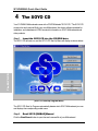
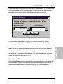
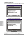
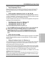
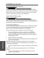
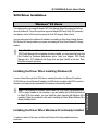
1
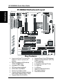
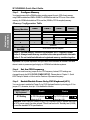
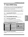
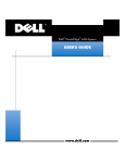
Introduction
The SOYO CD
Quick BIOS
Setup
Hardware
Installation
SY-D6IBA2
Motherboard
SCSI Utilities
Quick Start Guide
Tested To Comply
With FCC Standards
FOR HOME OR OFFICE USE
C
FC
100%
POST CONSUMER
RECYCLED PAPER
SOYO ™
SY-D6IBA2 Motherboard
Single or Dual Pentium ® III & Pentium ® II processors
supported
82440 BX AGP/PCI Motherboard
66&100MHz Front Side Bus supported
ATX Form Factor
Copyright © 1999 bySoyo Computer Inc.
Trademarks:
Soyo is a registered trademark of Soyo Computer Inc. All trademarks are the property of their
owners.
Product Rights:
Product and corporate names mentioned in this publication are used for identification purposes
only and may be registered trademarks or copyrights of their respective companies.
Copyright Notice:
All rights reserved. This manual is copyrighted by Soyo Computer Inc. You may not reproduce,
transmit, transcribe, store in a retrieval system, or translate into any language, in any form or by
any means, electronic, mechanical, magnetic, optical, chemical, manual or otherwise, any part of
this publication without express written permission of Soyo Computer Inc.
Disclaimer:
Soyo Computer Inc. makes no representations or warranties regarding the contents of this
manual. We reserve the right to revise the manual or make changes in the specifications of the
product described within it at any time without notice and without obligation to notify any
person of such revision or change. The information contained in this manual is provided for
general use by our customers. Our customers should be aware that the personal computer field is
the subject of many patents. Our customers should ensure that their use of our products does not
infringe upon any patents. It is the policy of Soyo Computer Inc. to respect the valid patent rights
of third parties and not to infringe upon or assist others to infringe upon such rights.
Restricted Rights Legend:
Use, duplication, or disclosure by the Government is subject to restrictions set forth in
subparagraph (c)(1)(ii) of the Rights in Technical Data and Computer Software clause at
252.277-7013.
About This Guide:
This Quick Start Guide is for assisting system manufacturers and end users in setting up and
installing the Motherboard. Information in this guide has been carefully checked for reliability;
however, no guarantee is given as to the correctness of the contents. The information in this
document is subject to change without notice.
If you need any further information, please visit our Web Site on the Internet. The address is
"http://www.soyo.com.tw".
D6IBA2 Serial - Version 1.0 - Edition: April 1999
* These specifications are subject to change without notice
2
1
Introduction
Congratulations on your purchase of the SY-D6IBA2 Motherboard. This Quick Start Guide
describes the steps for installing and setting up your new Motherboard.
This guide is designed for all users to provide the basic steps of Motherboard setting and
operation. For further information, please refer to SY-D6IBA2 Motherboard User's Guide and
Technical Reference online manual included on the CD-ROM packed with your
Motherboard.
Unpacking
* If your board comes with a driver disc and a paper manual, the Quick Start Guide and the CD-ROM are not included in the package.
When unpacking the Motherboard, check for the following items:
u The SY-D6IBA2 82440 BX AGP/PCI Motherboard
u This Quick Start Guide
u The Installation CD-ROM
u Three SCSI Driver Installation Diskettes
labeled “7800 Family Manager Set V3.01”(optional)
u Two CPU Retention sets
u One IDE Device Flat Cable
u One Floppy Disk Drive Flat Cable
u One 50-pin Narrow SCSI Cable (optional)
u One 68-pin Wide SCSI Cable (optional)
u One 68-pin Ultra2 SCSI Cable (optional)
3
Introduction
SY-D6IBA2 Quick Start Guide
SY-D6IBA2 Quick Start Guide
Introduction
SY-D6IBA2 Motherboard Layout
PS/2 KB PS/2 Mouse
Connector Connector
JP1
1
USB 1
1
1
FAN1
CPUFAN
3
FAN2
DIMM 1
DIMM 2
DIMM 3
DIMM 4
CPUFAN
USB 2
Slot 1 #2
Slot 1 #1
PRT
Hardware Monitoring
COM 1
W83781D
828AC
Winbond
W83781D
COM 2
Intel
ATX
Power
82443 BX
1
AGP Slot
1
1
IR1
5
1
IDE 2
FDC
IDE 1
PCI Slot #4
Ultra
I/O Chipset
Winbond
83977EF-AW
PCI Slot #3
JP7
(Optional)
Intel
SB-LINK
(PC-PCI)
PCI Slot #2
82371 EB
adaptec
AIC - 7890AB
JP4
3
PCI Slot #1
SCSI HDD AQWA741
LED
1
Wide SCSI (68-pin)(Optional)
Flash BIOS
JP53
3V
Lithium
Battery
1
1
1
1
CMOS Clear
Jumper
ISA Slot #1
Ultra2 SCSI (68-pin) (Optional)
Narrow SCSI (50-pin)
(Optional)
ISA Slot #2
Adaptec
AIC-3860
Power
LED Keylock Speaker
+
Ø
Supports Intel Pentium® III processor (450550MHz) & Pentium® II processor (233450MHz)
Ø
Ø
Ø
Easy CPU settings in BIOS with the
“SOYO COMBO Setup”
Auto-detect CPU voltage
SCSI port onboard (optional)
PC98, APM, Ultra DMA/33
Power-on by modem or alarm
Supports onboard hardware monitoring
and includes Hardware Doctor ™ utility
Supports Wake-On-LAN (WOL)
Ø
Ø
Ø
Ø
Ø
Ø
Ø
Ø
Ø
Ø
Ø
Ø
Ø
4
_
+
+
_
+
_
Reset PWRBT Turbo HDD LED
LED
1
JP44
1
Key Features
_
3
WOL
Header
FAN3
Supports Power-On by PS/2 Keyboard
Supports Creative SB-LINK ™ (PC-PCI)
for PCI audio card
1 x 32-bit AGP slot
4 x 32-bit bus mastering PCI slots
2 x USB ports
1 x IrDA port
Supports multiple-boot function
ATX power connector
Power failure resume
SY-D6IBA2 Quick Start Guide
2
Installation
l
Before handling the Motherboard, ground yourself by grasping an unpainted portion
of the system's metal chassis.
l
Remove the Motherboard from its anti-static packaging. Hold it by the edges and
avoid touching its components.
l
Check the Motherboard for damage. If any chip appears loose, press carefully to seat
it firmly in its socket.
Follow the directions in this section designed to guide you through a quick and correct
installation of your new SY-D6IBA2 Motherboard. For detailed information, please refer to
SY-D6IBA2 Motherboard User's Guide and Technical Reference online manual included on
the CD-ROM packed with your Motherboard.
PREPARATIONS
Gather and prepare all the necessary hardware equipment to complete the installation
successfully:
u
u
u
u
u
u
u
u
u
u
u
u
Slot 1 processor with built-in CPU cooling fan (boxed type)
SDRAM module
Computer case and chassis with adequate power supply unit
Monitor
PS/2 Keyboard
Pointing Device (PS/2 Mouse)
VGA Card
Sound Card (optional)
Speaker(s) (optional)
Disk Drives: HDD, CD-ROM, Floppy drive …
External Peripherals: Printer, Plotter, and Modem (optional)
Internal Peripherals: Modem and LAN cards (optional)
5
Hardware
Installation
To avoid damage to your Motherboard, follow these simple rules while
handling this equipment:
SY-D6IBA2 Quick Start Guide
Install the Motherboard
Follow the steps below in order to perform the installation of your new SY-D6IBA Motherboard.
Step 1.
Install the CPU
: Record the working frequency of your CPU that should be clearly marked on the CPU cover.
FSB 66MHz
266MHz (66 x 4.0)
300MHz (66 x 4.5)
333MHz (66 x 5.0)
366MHz (66 x 5.5)
400MHz (66 x 6.0)
433MHz (66 x 6.5)
450MHz (100 x 4.5)
500MHz (100 x 5.0)
550MHz (100 x 5.5)
600MHz (100 x 6.0)
Hardware
Installation
FSB 100MHz
350MHz (100 x 3. 5)
400MHz (100 x 4.0)
Notice 1: When installing two processors, please make sure the front side bus and working
frequency are identical for both processors.
Notice 2: If you are using a single processor, preferably install the processor in Slot 1 #1,
leaving Slot 1 #2 empty for future expansion to dual CPU.
Retention Module
Step 1.
Open the two sides by folding them up.
Step 2.
Push the locks on top of the CPU
inward.
Step 3.
Insert the CPU into the retention
module. The CPU fits in the CPU slot in
only ONE way, do not try to force it in.
Step 4.
After completely inserting the CPU, push the two locks on
top of the CPU outward. Now your CPU is ready for use.
To remove the CPU, press
the two notches on top of
the CPU inward. Now
press the two slides on the
retention module down and
remove the CPU.
6
SY-D6IBA2 Quick Start Guide
Note: Installing a heat sink and cooling fan on top of your CPU is necessary for
proper heat dissipation. Failing to install these items may result in overheating
and possible burn-out of your CPU.
Make Connections to the Motherboard
Step 2.
For more details on how to connect internal and external peripherals to your new SYD6IBA2 Motherboard, please refer to SY-D6IBA2 Motherboard User's Guide and Technical
Reference online manual on CD-ROM.
Connectors and Plug-ins
PCI Audio Card Header: SB-Link ™(PC-PCI)
Wake-On-LAN Header: JP44
Connect the SB-Link ™(PC-PCI) cable from your PCI audio
card to this header.
Slot 1 #1 CPU
Cooling Fan: FAN 1
Pin1
GND
Pin2
12V
_
+
Pin1
GND
Pin2
12V
Pin1
5V
LED Anode
Pin1
GND
Pin2
12V
Keylock
Pin3
GND
Pin1
Control Pin
Pin2
Pin3
NC
NC
5V
Turbo LED
Pin1
LED
Cathode
Pin2
NC
Pin3
SENSOR
Pin2
GND
Speaker
Pin1
Reset PWRBT Turbo LED HDD LED
Pin2
LED
Cathode
Chassis Fan: FAN 3
Power LED
_
+ _+ _
Pine1
Pin3
MP-Wakeup
Pin3
SENSOR
Speaker
+
HDD LED
Pin2
GND
Slot 1 #2 CPU
Cooling Fan: FAN 2
Pin3
SENSOR
Power LED Key Lock
Pin1
5VSB
PWRBT
Pin1
Power
On/Off
Pin2
GND
Pin2
GND
Pin4
Speaker out
RESET
Pin1
Power
Good
Pin2
GND
IrDA (Infrared Device Header): IR1
Pin1
VCC
Pin2
None
Pin3
IRRX
ATX Power On/Off: PWRBT
Connect your power switch to this
header (momentary switch type).
To turn off the system,
please press this switch and hold
down for longer than
4 seconds.
Pin4
GND
Pin5
IRTX
ATX Power Supply: ATX PW
Attach the ATX Power cable to this connector.
When using the Power-On by PS/2 Keyboard
function, please make sure the ATX power supply
can take at least 720mA load on the 5V Standby lead
(5VSB) to meet the standard ATX specifications.
7
Hardware
Installation
This section tells how to connect internal peripherals and power supply to the Motherboard.
Internal peripherals include IDE devices (HDD, CD-ROM), Floppy Disk Drive, Chassis Fan,
Front Panel Devices (Turbo LED, Internal Speaker, Reset Button, IDE LED, and KeyLock
Switch.), Wake-On-LAN card, VGA card, Sound Card, and other devices.
SY-D6IBA2 Quick Start Guide
Step 3.
Configure Memory
Your board comes with four DIMM sockets, providing support for up to 1GB of main memory
using DIMM modules from 8MB to 256MB. For 66MHz front side bus CPUs use 12ns or faster
memory; for 100MHz front side bus CPUs use 8ns (100MHz, PC100 compliant) memory.
Hardware
Installation
Memory Configuration Table
Number of
Memory Modules
DIMM 1
1
1st
2
1st
2nd
3
1st
2nd
3rd
4
1st
2nd
3rd
DIMM 2
DIMM 3
DIMM 4
4th
RAM Type
SDRAM
Memory Module
8/16/32/64/128/256 Mbytes
Size (MB)
Notice 1: 256 MB memory modules only available on PC registered DIMM.
Notice 2: Always install memory modules in the order prescribed in this table.
Notice 3: Do not install unbuffered and registered memory modules together.
Important: It is of prime importance that you install DIMM modules as outlined in the table
above in order to preserve signal integrity on 100MHz front side bus systems.
Step 4.
Set the CPU Frequency
You do not need to set any jumper for the CPU frequency. Instead, CPU settings are
changed through the BIOS [SOYO COMBO SETUP]. Please refer to Chapter 3 - Quick
BIOS Setup for details on how to set the Pentium® II processor frequency.
Step 5.
Enable/Disable Power-On by PS/2 Keyboard (JP1)
You can choose to enable the Power-On by PS/2 Keyboard function by shorting pin 2-3 on
jumper JP1, otherwise, short pin 1-2 to disable this function.
Support Power-On
by Keyboard
Enable
Disable
Enable Power-On
Disable Power-On
by PS/2 Keyboard
by PS/2 Keyboard
1 2 3
1 2 3
(short pin 2-3)
(short pin 1-2)
Important: When using the Power-On by PS/2 Keyboard function, please make sure
the ATX power supply can take at least 720mA load on the 5V Standby lead (5VSB)
to meet the standard ATX specifications.
JP1 Setting
8
SY-D6IBA2 Quick Start Guide
Step 6.
Power Button Enable (JP7)
Your system can be power on by either pressing a power button or typing in a password,
which can be set in the BIOS SOYO COMBO Setup. To avoid being unable to power up the
system due to of forgetting the password, you can place a jumper cap to short JP7. This will
always enable the Power Button.
JP7 Setting
Step 7.
Power Button always
enabled
Short pin to always
enable the Power
Button.
Power Button according to
BIOS setting
Open pin for a Power
Button function according
to the BIOS setting.
Clear CMOS Data (JP5)
Clear the CMOS memory by momentarily shorting pin 2-3 on jumper JP5 for at least 5
seconds, and then by shorting pin 1-2 to retain new settings. This jumper can be easily
identified by its white colored cap.
CMOS Clearing
JP5 Setting
Retain CMOS Data
Short pin 1-2 to retain
the new settings.
1
Clear CMOS Data
2 3
Short pin 2-3 for
at least 5 seconds
to clear the CMOS. 1 2 3
Note: You must unplug the ATX power cable from the ATX power connector when
performing the CMOS Clear operation.
9
Hardware
Installation
Power Button
Enable
SY-D6IBA2 Quick Start Guide
Note on Over-clocking Capability
Hardware
Installation
The SY-D6IBA2 Motherboard provides over-clocking capability. Due to the over-clocking
setting your system may fail to boot up or hang during run time. If this occurs, please perform
the following steps to recover your system from the abnormal situation:
1.
Turn off system power. (If you use an ATX power supply, and depending on your
system, you may have to press the power button for more than 4 seconds to shut
down the system.)
2.
Press and hold down the <Insert> key while turning on the system power. Keep
holding down the <Insert> key until you see the message of the CPU type and
frequency (133MHz or 200MHz) appear on screen.
3.
Press the <Del> key during the system diagnostic checks to enter the Award BIOS
Setup program.
4.
From the BIOS main menu, select [SOYO COMBO SETUP] and move the cursor to
the [CPU Frequency] field to set the proper working frequency.
5.
Select [Save & Exit SETUP] and press <Enter> to save the configuration to the
CMOS memory, and continue the boot sequence.
Note: SOYO does not guarantee system stability if the user over clocks the system.
Any malfunctions due to over-clocking are not covered by the warranty.
10
SY-D6IBA2 Quick Start Guide
3
Quick BIOS Setup
This Motherboard does not use any hardware jumpers to set the CPU frequency. Instead,
CPU settings are software configurable with the BIOS [SOYO COMBO SETUP]. The
[SOYO COMBO SETUP] menu combines the main CPU parameters that you need to
configure, all in one menu, for a quick setup in BIOS.
After the hardware installation is complete, turn the power switch on, then press the <DEL> key
during the system diagnostic checks to enter the Award BIOS Setup program. The CMOS
SETUP UTILITY will display on screen. Then, follow these steps to configure the CPU settings.
Step 1.
Select [LOAD SETUP DEFAULT]
Step 2.
Select [STANDARD CMOS SETUP]
Set [Date/Time] and [Floppy drive type], and then set [Hard Disk Type] to “Auto”.
Step 3.
Select [SOYO COMBO SETUP]
Move the cursor to the [CPU Speed] field to set the CPU working frequency.
Available [CPU Speed] settings on your SY-D6IBA2 Motherboard are detailed in the
following table. If you set this field to [Manual], you are then required to fill in the next two
consecutive fields: (1) the CPU Host Clock, and (2) the CPU Ratio.
CPU Frequency
233MHz (66 x 3.5)
350MHz (100 x 3.5)
266MHz (66 x 4.0)
400MHz (100 x 4.0)
300MHz (66 x 4.5)
450MHz (100 x 4.5)
333MHz (66 x 5.0)
500MHz (100 x 5.0)
366MHz (66 x 5.5)
550MHz (100 x 5.5)
400MHz (66 x 6.0)
600MHz (100 x 6.0)
Select the working frequency of
your Pentium® III, Pentium® II
processor among these preset
values.
Note:
Mark the checkbox that
corresponds to the working
frequency of your Pentium® III,
Pentium® II processor in case the
CMOS configuration should be lost.
433MHz (66 x 6.5)
Step 4.
Select [SAVE & EXIT SETUP]
Press <Enter> to save the new configuration to the CMOS memory, and continue the boot
sequence.
11
Quick BIOS
Setup
Select the “LOAD SETUP DEFAULT”menu and type “Y”at the prompt to load the BIOS
optimal setup.
SY-D6IBA2 Quick Start Guide
4
The SOYO CD
Your SY-D6IBA2 Motherboard comes with a CD-ROM labeled "SOYO CD." The SOYO CD
contains the user's manual file for your new Motherboard, the drivers software available for
installation, and a database in HTML format with information on SOYO Motherboards and
other products.
Step 1.
Insert the SOYO CD into the CD-ROM drive
The SOYO CD
The SOYO CD will auto-run, and the SOYO CD Start Up Menu will display as shown below.
(SOYO CD Start Up Program Menu)
The SOYO CD Start Up Program automatically detects which SOYO Motherboard you own
and displays the corresponding model name.
Step 2.
Read SOYO [D6IBA2] Manual
Click the Read Manual button to open the user's manual file of your Motherboard.
12
SY-D6IBA2 Quick Start Guide
Please note that if the Start Up program was unable to determine which SOYO Motherboard
you own, the manual selection menu will pop up, as shown below. Then select the user's
manual file that corresponds to your Motherboard model name and click OK.
SOYO CD Manuals
Please select your manual in the box below
and click OK.
686 boards:
586 boards:
D6IBA2
OK
Back
(Manual Selection Menu)
Note: The Start Up program automatically detects if the Acrobat Reader utility is already
present in your system, and otherwise prompts you on whether or not you want to install it.
You must install the Acrobat Reader utility to be able to read the user's manual file. Follow
the instructions on your screen during installation, then once the installation is completed,
restart your system and re-run the SOYO CD.
Step 3.
Install Drivers
Click the Install Drivers button to display the list of drivers software that can be installed with
your Motherboard. The Start Up program displays the drivers available for the particular
model of Motherboard you own. We recommend that you only install those drivers.
13
The SOYO CD
The user's manual files included on the SOYO CD can be read in PDF (Postscript
Document) format. In order to read a PDF file, the appropriate Acrobat Reader software
must be installed in your system.
SY-D6IBA2 Quick Start Guide
The following drivers are available for Windows 95
Driver Installation
Please select the driver you want to install and click OK, You will have to
restart your system after installation. Only the drivers that are relevant
to your board are displayed initially.
Intel Southbridge Drivers
SOYO Speedpro BusMaster Driver for win 95/98
Intel BusMaster Drivers for Win NT
Intel BusMaster Drivers for Win95
Intel BusMaster Drivers for OS/2
SOYO CD Xpress utility
Winbond hardware doctor for win 95/98
Cancel
Display all drivers
on the SOYO CD
OK
(Driver Installation Menu)
The following drivers are available for Windows 98
The SOYO CD
Driver Installation
Please select the driver you want to install and click OK, You will have to
restart your system after installation. Only the drivers that are relevant
to your board are displayed initially.
SOYO Speedpro BusMaster Driver for win 95/98
Intel BusMaster Drivers for Win NT
Intel BusMaster Drivers for OS/2
SOYO CD Xpress utility
Winbond hardware doctor for win 95/98
Cancel
Display all drivers
on the SOYO CD
OK
(Driver Installation Menu)
However, to display the list of all drivers software available with SOYO Motherboards, click
the Display all drivers on the SOYO CD button. Please make sure to install only the
drivers adapted to your system, or otherwise this cause system malfunctions.
14
SY-D6IBA2 Quick Start Guide
A short description of all available drivers follows:
Ø
Intel Southbridge Drivers
Because Windows 95 does not recognize the Southbridge of the newer Intel chipsets (TX,
BX, ZX etc) this utility has to be run, it will update the necessary Windows files. (Only for
Windows 95)
Ø
SOYO SpeedPro Busmaster Driver for Win 95/98
Without the busmaster drivers the CPU will need to be involved every time data is read from
or written to the Harddisk. The busmaster drivers make use of DMA (Direct Memory Access)
to relieve the CPU of this burden, thus speeding up the system.
The SOYO SpeedPro driver makes use of an advanced caching algorithm, which gives it an
advantage over other busmaster drivers.
Ø
Intel Busmaster Drivers for Windows 95
Ø
Intel Busmaster Drivers for Win NT
Ø
Intel Busmaster Drivers for OS/2
These are the official busmaster drivers as supplied by Intel.
Ø
SOYO CD Xpress Utility
This utility will enhance your CD-ROM Drive data-thoughput by using space on the Harddisk
as cache. This way application programs can access data faster. This utility is suitable for
Windows 95/98.
Ø
Winbond hardware doctor for Windows xx
Your motherboard comes with a hardware monitoring IC. By installing this utility Temperature,
Fan speed and Voltages can be monitored. It is also possible to set alarms when current
system values exceed or fall below pre-set values.
This utility comes with a preset monitoring rage for the CPU voltage. However, the core voltage
of the processor you purchased may fall out of this preset range, so you may need to adjust the
pre-set value. Please refer to the SY-D6IBA2 Motherboard’s CD manual for the details.
Select which driver you want to install and click OK, or click Cancel to abort the driver
installation and return to the main menu.
Note 1: Once you have selected a driver, the system will automatically exit the SOYO CD to
begin the driver installation program. When the installation is complete, most drivers require
to restart your system before they can become active.
15
The SOYO CD
Note: Do NEVER install two types of busmaster drivers on your system, this will
lead to conflicts and system instability. Therefore, if you install the SOYO
SpeedPro Busmaster driver you can NOT install the Intel Busmaster drivers.
Before installing a new busmaster driver first UNINSTALL the old busmaster
driver.
SY-D6IBA2 Quick Start Guide
Note 2: EZ-SCSI Utility: The SCSI utility for use with the onboard Adaptec® SCSI chip is
located in the \drivers\EZ-SCSI directory. EZ-SCSI is suitable for DOS or Windows 3.1
environment only. The manual file in PDF format can be found at the following location:
\Manual\EZ-SCSI.pdf.
Step 4.
Check the Latest Releases
Click the 'Check the latest Releases' button to go the SOYO Website to automatically find
the latest BIOS, manual and driver releases for your motherboard. This button will only work
if your computer is connected to the internet through a network or modem connection. Make
sure to get your modem connection up before clicking this button.
Step 5.
Enter the SOYO CD
Click the Enter SOYO CD button to enter the SOYO HTML database. The Start Up
program will activate the default HTML browser installed on your system (for example,
Internet Explorer or Netscape) to visualize the contents of the SOYO CD.
The SOYO CD
The SOYO CD contains useful information about your Motherboard and other SOYO
products available. For your convenience, this information is available in HTML format,
similar to the format widely used on the Internet.
(SOYO CD HTML Database in English*)
Note: If no HTML browser is installed on your system, the Start Up program will prompt you
on whether or not you would like to install the Internet Explorer* browser. Click YES to install
the HTML browser. After the installation is complete, please restart your system. Then re-run
the SOYO CD and you will be able to browse the SOYO HTML database.
(* Internet Explorer is a Microsoft Trademark)
16
SY-D6IBA2 Quick Start Guide
5
SCSI Utilities
Ultra2 SCSI I/O Subsystem
Your new SYD6IBA2 high-performance Motherboard is equipped with the onboard
Adaptec® AIC-7890 Ultra2 SCSI host adapter for your high bandwidth applications, providing
data transfer rates of up to 80 Mbytes per second. The Ultra2 SCSI is an input/output bus
interface that provides a powerful multitasking interface between your computer’s PCI bus
and your SCSI devices.
With SCSI, you can connect a variety of devices on your computer (Hard/Floppy Disk Drives,
CD-ROM Drives, Scanners, Tape Drives, Removable Media Drives, etc.) in a daisy-chain
topology to a common host adapter. Daisy-chaining SCSI devices allows them to
communicate with each other by sending commands and data via the SCSI bus.
The AIC-7890 Ultra2 SCSI provides maximum data transfer rates of 20 Mbytes/sec in the
narrow 8-bit mode (Fast SCSI) and 40 Mbytes/sec in the wide 16-bit mode (Ultra SCSI), and
80 Mbytes/sec in the LVD mode (Ultra2 SCSI)
Installing SCSI Devices
Your Motherboard features two internal SCSI connectors onboard, and comes with one 50pin flat cable, one 68-pin flat cable, and one 68-pin Ultra2 cable.
50-pin Fast SCSI Connector
50-pin Fast SCSI internal connector
If you are connecting more than 2 internal SCSI devices, you must use an internal SCSI
cable with enough connectors to accommodate all your devices. Contact your dealer for
special cable service.
When Fast SCSI devices are connected to the bus, the total length of all cables is not to
exceed 3 meters (9.8 ft.) to ensure reliable operation.
17
SCSI Utilities
Narrow SCSI allows data transfer rates of up to 20 Mbytes/sec. With Narrow SCSI, you can
connect up to 7 internal Fast SCSI devices to the 50-pin Fast SCSI connector on the
Motherboard. Use the enclosed Narrow SCSI cable to connect up to 2 internal SCSI
devices.
SY-D6IBA2 Quick Start Guide
68-pin Ultra-Wide SCSI Connector
68-pin Ultra-Wide SCSI internal connector
Ultra-Wide SCSI allows you to connect up to 15 devices (7 Narrow internal and 8 Wide
internal or external SCSI devices, or 15 Wide internal or external SCSI devices) to the 68-pin
Ultra-Wide SCSI connector on the Motherboard. Devices that connect to the 16-bit Wide
SCSI bus can transfer data at the maximum rate of 40 Mbytes/sec.
68-pin Ultra2 SCSI Connector
68-pin Ultra2 SCSI internal connector
Ultra2 SCSI allows you to connect up to 15 devices (LVD/SE mode) to the 68-pin Ultra2
SCSI connector on the Motherboard. Devices that connect to the 16-bit Ultra2 SCSI bus can
transfer data at the maximum rate of 80 Mbytes/sec.
Connecting Internal SCSI Devices
If you are connecting several internal SCSI devices (more than 2 SCSI devices), make sure
you have an internal SCSI cable with enough connectors to accommodate all of your
devices. The enclosed SCSI flat cables can serve up to 2 SCSI devices.
SCSI Utilities
Follow these steps to ensure a proper installation of your internal SCSI devices:
1.
Prepare each SCSI devices for installation; configure the device SCSI ID and
terminators (terminate the last internal device attached to the cable by setting its
termination to the ON position; all other internal devices on the SCSI bus must have
their termination set to OFF).
2.
Install the SCSI devices in your computer.
3.
Plug the connector at one end of the internal SCSI cable into the host adapter’s SCSI
connector on the Motherboard.
Note: Make sure the cable’s colored stripe is aligned with pin-1 of the host adapter’s
connector. Pin-1 of the SCSI connector is usually designated by a small triangle (5), or a
“1”at one corner of the connector.
4.
Connect the remaining connectors on the cable to the SCSI devices (CD-ROM drives,
etc.).
Note: Make sure the cable’s colored stripe is aligned with pin-1 of the SCSI device’s
connector.
5.
Connect a DC power cable (from your computer’s power supply) to the power
connector on each SCSI device.
18
SY-D6IBA2 Quick Start Guide
SCSI Driver Installation
Windows® 95 Users
This chapter explains how to install the Adaptec 7800 Family Manager Set aic78xx.mpd and aic78u2.mpd
drivers for Windows 95. The aic78xx.mpd driver supports all Adaptec7800 Family Ultra2 SCSI (and earlier)
host adapters, and the aic78u2.mpd driver supports all Ultra2 SCSI adapters. Refer to the list.
If you are performing a first time Windows 95 installation, see Installing the Driver When Installing Windows
95 If Windows 95 is already installed in your system, see Installing the Driver When Windows 95 is Already
Installed.
Note: When Windows 95 starts, if a New Hardware Found dialog is displayed after your
7800 Family Manager Set host adapter has been installed, you must select the Driver from
Disk Provided by Hardware Manufacturer option. Insert your Adaptec 7800 Family
Manager Set v. 3.01 diskette into the floppy drive and type a:\win95 as the path. Then,
follow the on screen instructions.
Installing the Driver When Installing Windows 95
Note: If the Windows 95 installation cannot detect the 7800 Family host adapter(Ultra2
SCSI or earlier) installed in your computer, or you are installing the aic78u2.mpd driver for
an Ultra2 SCSI host adapter, you must install the driver manually after Windows 95 is
complete. Follow the procedures in the section Installing the Driver When Windows 95 is
Already Installed, below
Installing the Driver When Windows 95 is Already Installed
To update or install the aic78xx.mpd or aic78u2.mpd if Windows 95 is already installed, follow these
instructions:
19
SCSI Utilities
A version of the aic78xx.mpd (Ultra2 SCSI) driver is embedded (included) in the Windows 95 installation
CD-ROM. During a normal Windows 95 installation, the 7800 Family host adapter (Ultra2 SCSI or earlier) is
detected in your system and the embedded aic78xx.mpd driver is automatically installed.
SY-D6IBA2 Quick Start Guide
Note: All Adaptec 7800 Family Ultra2 SCSI (and earlier) host adapters use the
aic78xx.mpd driver. Ultra2 SCSI adapters use the aic78u2.mpd driver. Once the correct
driver is updated, it is not necessary to update it again for each 7800 Family host adapter
installed in your system.
1.
2.
3.
4.
5.
Start Windows 95.
Click the [Start] button on the Windows 95 task bar, and then point to Settings.
Click [Control Panel].
Double-click the [System] icon.
On the Device Manager tab, click the plus sign (+) next to the SCSI controller icon.
Note: If Windows 95 cannot determine the type of host adapter installed in your
computer, a yellow question mark labeled Other devices appears instead of the JSCSI
controller icon. To continue, click the plus sign (+) next to the question mark; a yellow
question mark labeled PCI SCSI Bus Controller then appears.
6.
7.
8.
Double-click the 7800 Family host adapter you wish to update, or if a yellow question mark labeled
PCI SCSI Bus Controller is displayed, double-click the question mark.
Insert the Adaptec 7800 Family Manager Set v.3.01 diskette into drive A.
Select the Drives tab
SCSI Utilities
Note: If the version of Windows 95 you are using displays an Update Drivers button
instead of a [Change Driver] button, follow the procedures in the section Updating the
Driver for Windows 95 (Version OSR2).
9.
10.
11.
12.
13.
14.
Click [Change Driver]. If you are prompted to select the hardware type, select [SCSI Controller].
Click the [Have Disk] button and enter a:\win95 as the path.
Click [OK]
Select the 7800 Family host adapter, and click [OK].
Click [OK]. The driver is copied and scanned.
You must restart your computer for the changes to take effect. Click [Yes] to restart your computer.
Click [No] to return to the system properties window.
20
SY-D6IBA2 Quick Start Guide
Updating the Driver for Windows 95 (Version OSR2)
This section covers the remaining steps for updating the drives.
1.
Follow steps 1 through 7 in the Previous section, Installing the Driver When Windows 95 is Already
Installed.
2.
Click [Update Drivers].
3.
In the Update Device Driver Wizard, select [Yes], then click [Next].
4.
Under Location type a:\win95, then click [OK].
5.
Click [Finish].
6.
The message Please insert the disk labeled ‘7800 Family Manager Set v.3.01 Installation Disk’
appears dialog box. Click [OK].
7.
In the Copying Files dialog box, a message starting that ‘The file AIC 78XX.MPD or AIC78U2.MPD
on 7800 Family Manager Set V3.01 installation disk could not be found …’ appears. Type a:\win95
and click [OK] to install the driver.
8.
Click [Yes] to restart you computer to update the changes. To return to the System Properties
windows, click [OK].
SCSI Utilities
Note: If you wish to re-update the driver again, you must select No at step 3 above, then
click Next and follow the onscreen instruction \s to re-update.
21
SY-D6IBA2 Quick Start Guide
Windows® NT Users
This chapter explains how to install the Adaptec 7800 Family Manager Set and aic78u2.sys driver for
Windows NT. The aic78xx.sys driver supports all Adaptec 7800 Family Ultra2 SCSI (and earlier) host
adapters, and the aic78u2.sys driver supports all Ultra2 SCSI adapters.
If you are performing a first time Windows NT installation, see Installing the Driver When installing Windows
NT. If Windows NT is already installed in your system, see Installing the Driver When Windows NT is
Already Installed.
Installing the Driver When Installing Windows NT
A version of the aic78xx.sys driver (Ultra2 SCSI) driver is embedded (Included) in the Windows NT 3.5x and
4.0 installation disks (or CD-ROM). During a normal Windows NT installation, the 7800 Family host adapter
is detected in your system and the embedded driver is automatically installed.
Note: If you are booting from a 7800 Family host adapter and you are unable to install
the embedded aic78xx.sys driver by performing a Windows NT installation, follow the
instructions for completing a fresh Windows NT installation.
The aic78u2.sys driver (Ultra2 SCSI) is not embedded on the Windows NT 3.5x and 4.0 installation disks (or
CD-ROM) and must be installed after Windows NT has been installed. When completing the Windows
installation, you can update the driver by following the instructions in Installing the Driver When Windows NT
is Already Installed.
SCSI Utilities
Completing a Fresh Windows NT 3.5x Installation
1
2
3
4
If you choose to install Windows NT from a floppy drive, locate the Windows NT Setup Disk 1 for
Floppy Installation.
If you are installing from a CD-ROM drive, locate the Windows NT Setup Disk 1 for CD-ROM
Installation.
Insert the diskette into drive A(not drive B) and turn ON your computer. When prompted, insert
Windows NT Disk 2.
From the Welcome to Setup Screen, press [Enter] to set up Windows NT.
When prompted, select [Custom] setup.
22
SY-D6IBA2 Quick Start Guide
Note: If you are installing an Ultra2 SCSI host adapter such as the AHA-2940U2W, you
cannot select Express setup, because the aic78u2.sys driver is not embedded. Selecting
Express setup loads the embedded driver aic78xx.sys included with Windows NT which is for
Ultra SCSI adapters only.
6
7
8
9
10
11
Press [S] to skip mass storage device detection. This allows you to manually select the driver for
your host adapter.
Since mass storage device detection was skipped in the previous step, Windows NT Setup displays
none in the list of recognized devices. Press [S] to configure additional SCSI adapters.
From the list of additional SCSI adapters, expand the list, select [Other], and press [Enter] requires
disk provided by a hardware manufacturer.
Insert the Adaptec 7800 Family Manager Set diskette for Windows NT into drive A and press
[Enter].
The screen displays the adapter drivers supported on the diskette. For Window NT 3.5x, the
following is displayed:
Adaptec AHA-290x/291x/294x/4944/AIC-78xx PCI SCSI Controller (NT 3.5x)
or
Adaptec AHA-294xu2/AIC-7890/91 PCI Ultra2 SCSI Controller (NT3.5x)
Highlight the driver and press [Enter].
To add other host adapters that are not a part of the 7800 Family, do so at this time by repeat from
step 7 for each additional adapter and insert the appropriate driver disk. The Adaptec 7800 Family
host adapters use the same driver; it is not necessary to install the driver again.
Press [Enter] to continue with the Windows NT operating system setup. Follow the instructions
given onscreen and in the Windows NT installation documentation.
Completing a Fresh Windows NT 4.0 Installation
1
Start your system with the Window NT Boot Diskette in the floppy drive.
2
When prompted, insert diskette #2 in your floppy drive. After a few moments you will see a blue
screen. To setup Windows NT now, press [Enter].
3
Press [S] to skip auto-detection of your SCSI host adapter.
4
Press [S] again to specify an additional device.
5
Press [Enter] to select Others; insert the 7800 Family Manager Set diskette for Windows NT in your
floppy drive.
6
Select from the following drivers:
Adaptec AHA-290x/291x/294x/394x/4944/AIC-78xx PCI SCSI Controller (NT4.0)
or
Adaptec AHA-294xu2/AIC-7890/91 PCI Ultra2 SCSI Controller (NT 4.0)
23
SCSI Utilities
5
SY-D6IBA2 Quick Start Guide
7
8
9
Highlight a driver and press [Enter].
To add other host adapters that are not part of the 7800 Family, press [S] and repeat from Step4 for
each additional adapter and insert the appropriate driver disk. The Adaptec 7800 Family host
adapters use the same driver; it is not necessary to install the driver again.
Press [Enter] to continue with the Windows NT operating system setup. Follow the instructions
onscreen and in the Windows NT documentation to complete the installation.
Installing the Driver When Windows NT is Already Installed
To update or install the aic78xx.sys or aic78u2.sys driver if Windows NT is already installed, follow the
instructions below for the version of Windows NT you are installing.
Updating Windows NT 3.5x
1
2
3
4
SCSI Utilities
5
6
7
8
9
Select and start the Windows NT Setup program. (Its icon is usually found in the Main program
group0.) There is a brief pause while Windows NT Setup scans your hardware configuration.
Select the [Options] pull-down menu and then select Add/Remove SCSI Adapter]. The SCSI
Adapter setup program displays a list of all host adapters currently installed.
Click the [Add] button to add another host adapter type to the list. A list of additional SCSI adapters
appears.
Expand the list of additional SCSI adapters; select [Other] and press [Enter]. (Requires disk
provided by the hardware manufacturer.)
Insert the Adaptec 7800 Family Manager Set diskette for Windows NT into drive A; enter one of the
following paths to the installation files and then click [OK].
a:\winnt\3_5)
The screen displays the adapter drivers supported on the diskette:
Adaptec AHA-290x/291x/294x/4944/AIC-78xx PCI SCSI Controller (NT 3.5x)
Adaptec AHA-294xu2/AIC-7890/91 PCI Ultra2 SCSI Controller (NT 3.5x)
Highlight a driver, then click [OK]. The driver is added to the list of SCSI adapters.
Select the driver form the list of SCSI adapters and click [Install]. At this point, Windows NT Setup
checks to see if the specified driver has already been copied to the system disk.
If the following message appears, click [New] to replace the existing driver and skip to Step 10.
The driver(s) for this SCSI Adapter are already on the system. Do you want to use the
currently installed driver(s) or install new one(s).
If the following message appears, continue with Step9.
Please enter the full path to the Windows NT SCSI Adapter files.
Change the path to the a:\winnt\3_5 directory, then click [Continue].
The device driver is copied to your system disk and the Windows NT configuration is updated so
24
SY-D6IBA2 Quick Start Guide
10
11
12
13
that the new device driver loads when Window s NT reboots.
When the installation is complete, Windows NT Setup again displays a list of currently installed host
adapter types. Verify that the new host adapter appears on the list. The text string should look
similar to:
Adaptec AHA-290x/291x/294/4944/AIC-78xx PCI SCSI Controller (NT 3.5x)
or
Adaptec AHA-290xu/AIC-7890/91 PCI Ultra2 SCSI Controller (NT 3.5x)
Add other types of host adapters if necessary, or click [Close] to exit the SCSI adapters portion of
Windows NT Setup, and then close the program.
When you see this message, click [OK] to exit:
The changes you have made will not take effect until the computer is restarted.
If this message does not appear, no changes have been made to the Windows NT system
configuration.
Restart your computer and Windows NT. It is possible that some drive letter assignments may
change from the previous configuration.
1
2
3
4
5
6
7
8
9
10
11
12
Start Windows NT.
Click the [Start] button on the Windows NT task bar, and then point to Settings.
Click the [Control Panel].
Double-click the [SCSI Adapters]icon.
Click the [Drivers] tab, and then click the [Add] button.
In the Install Driver window, click the [Have Disk] button.
Insert the 7800 Family Manager Set diskette for Windows NT into drive A.
From the Copy Manufacturer’s File From text box, type a:\winnt\4.0, and click [OK].
In the Install Driver windows, Click [OK].
Click the [New] button when asked if you want to use the currently installed driver(s) or install new
one(s).
Type a:\winnt\4_0 again, and click [Continue]. The driver is now installed.
You must restart your computer for the changes to take effect. Click [Yes] to restart your computer.
Click [No] to return to the SCSI Adapters window.
Using Advanced Configurable Parameters
Advance users may use software parameters to alter the configuration of the Windows NT device drivers
sup0plied by Adaptec. All Windows NT configuration information is stored in a data structure called the
Registry. You can edit this information through a tool called the Registry Editor.
25
SCSI Utilities
Updating Windows NT 4.0
SY-D6IBA2 Quick Start Guide
Do not edit your registry unless it is absolutely necessary. If there is an error in
your registry, your computer may become nonfunctional.
Using Windows NT SCSI Parameters
Follow the instructions below to enter the registry values that affect how the Windows NT SCSI manager
interprets the generic configuration information of SCSI device drivers. All SCSI host adapters installed in
your system are affected by the values you enter here. A list of valid values follows.
Note: The following value keys are case-sensitive and must be entered exactly as
shown.
∗
∗
∗
∗
∗
DisableTaggedQueuing – A nonzero value indicates that the SCSI host adapter disabled tagged
queueing for SCSI devices. The data type for this value is REG_SZ.
DisableSynchronousTransfers – A nonzero value indicates that the SCSI host adapter is not to
initiate synchronous negotiations (but it may stall accept negotiations initiated by a SCSI target). The
data type for this value is REG_SZ.
DisableDisconnects – A nonzero value indicates that targets are not permitted to disconnect during
the execution of a SCSI command. The data type for this value is REG_DWORD.
MaximumLogicalUnit – This can limit the scan for connected devices on the SCSI bus. Valid values
are 1 to 8 If 1 is specified, the Windows NT SCSI manager assumes that no SCSI targets support
LUNs other than 0. Otherwise, LUNs from 0 to 8 are scanned during system initialization. The data
type for this value is REG_DWORD.
Maximum SGList – Specifies the maximum number of scatter-gather elements. Valid values are 17255. The data type for this value is REG_DWORD.
SCSI Utilities
To enter Windows NT parameters, follow these steps:
1
2
3
Select [Run] from the File menu (Windows NT 3.5x), or Run from the [Start] button (Windows NT
4.0).
Type regedt32 and press [Enter].
Open the registry list to the following location:
\HKEY_LOCAL_MACHINE\System\CurrentControlSet\Services\aic78xx\Parameters\Device
or
\HKEY_LOCAL_MACHINE\System\CurrentControlSet\Services\aic78u2\Parameters\Device
If the \Parameters\Device keys already exit, skip to step 8 below to begin entering values. If the keys
do not yet exist, you will need to create them by continuing with step 4.
26
SY-D6IBA2 Quick Start Guide
4
5
6
7
8
9
Click on the aic78xx or aic78u2 key.
Select [Add] Key from the Edit menu; Type device in the Key Name edit box. Leave the Class edit
box blank.
Click on the Parameters key.
Select [Add] Key from the Edit menu; Type Device in the Key Name edit box. Leave the Class edit
box blank.
To specify a certain host adapter, append device with the number of the host adapter. For example,
type Device0 for the first host adapter, jDevice1 for the second, etc. If you omit the host adapter
number, the configuration information applies to all 7800 Family host adapters.
Click on the Device key.
Select [Add Value] from the edit menu. In the Value Name edit box, enter one of the valid parameter
values. Make sure to enter the appropriate Data Type for the value. To enter additional values,
repeat steps 8-9.
Note: Changes made with the Registry Editor do not take effect until you shut down and
then restart your system.
Using Driver-specific Parameters
To use the Registry Editor to enter aic78xx.sys or aic78u2.sys driver-specific parameters that affect the
configuration information for Adaptec SCSI PCI device drivers, follow the instructions below. A list of valid
parameters follows.
∗
∗
∗
/INSTRUMENTAION – enables recording of I/O statistics and errors. If this option is not specified,
instrumentation defaults to disabled. The data type for this value is REG_SZ.
/INSTR_ERRIOG_Z=nnn – sets the maximum number of error log entries, if /INSTRUMENTATION
is enabled. If a number is not specified, the maximum number or error log entries defaults to 32. Valid
values are 0-128. The data type for this value is REG_SZ.
/MAXTAGS=nnn – specifies the tagged command queue depth. If a number is not specified, the
tagged queue depth defaults to 128. Valid values are 1-255. The data type for this value is REG_SZ.
27
SCSI Utilities
Note: The following parameters are case-sensitive and must be entered exactly as
shown. When entering multiple parameters, each parameter must be separated by a
space.
SY-D6IBA2 Quick Start Guide
To enter driver-specific parameters, follow these steps:
1
2
3
4
5
6
7
8
9
SCSI Utilities
10
Select [Run] from the File menu (Windows NT 3.5x), or Run form the Start button (Windows NT
4.0).
Type regedt32 and press [Enter].
Open the registry list to the following location:
\HKEY_LOCAL_MACHINE\System\CurrentCJontrolSet\Services\aic78xx\Parameters\Device\Driv
erParameters
or
\HKEY_LOCAL_MACHINE\System\CurrentCJontrolSet\Services\aic78u2\Parameters\Device\Driv
eParameters
If the \Parameters\Device\DriverParameters keys already exist, skip to step 10 below to begin
entering parameters. If the keys do not yet exist, you will need to create them by continuing with step
4.
Click on the aic78xx or aic78u2 key.
Select Add Key from the Edit menu; Type Parameters in the Key Name edit box. Leave the Class
edit box blank.
Click on the Parameters key.
Select Add Key from the Edit menu; Type Device in the Key Name edit box. Leave the Class edit
box blank.
To specify a certain host adapter, append Device with the number of the host adapter. For example,
type Device0 for the first host adapter, jDevice1 for the second, etc. If you omit the host adapter
number, the configuration information applies to all 7800 Family host adapters.
Click on the Device key.
Select Add Value from the Edit menu; type DriverParameters in the Key Name edit box. Enter
REG_SZ as the Data Type and press [Enter].
A String Editor text box appears. Enter valid parameters in the text box. When entering multiple
parameters, each parameter must be separated by a space.
Note: Changes made with the Registry Editor do not take effect until you shut down and
then restart your system.
28
SY-D6IBA2 Quick Start Guide
Using Windows NT and the Host Adapter
This section contains useful information on using Windows NT and your host adapter.
Removing a Host Adapter
Removing a host adapter can be as simple as physically removing it from the slot when your computer is
shut down. Windows NT boots and functions properly in this configuration, but a warning message is
generated every time you boot Windows NT.
If you have removed a host adapter but still have other host adapters of the
same type installed in your computer, do not use Windows NT Setup to
remove the device driver.
To eliminate the warning message, you must update the Windows NT software configuration, as described
below:
Removing a Host Adapter in Windows NT 3.5x
2.
3.
4.
5.
6.
7.
8.
Start the Windows NT Setup Program. There is a brief pause while Windows NT Setup scans your
hardware configuration.
Select the [Options] pull-down menu and then select [Add/Remove SCSI Adapters]. The SCSI
Adapter setup program displays a list of all host adapters currently installed.
Select the host adapter you want to remove and click the [Remove] button. When the Windows NT
Setup program asks you for confirmation, click [OK].
Because SCSI device drivers are loaded during system bootup and because they may be needed
to load Windows NT itself, a screen may appear warning you that Windows NT may not start if you
remove the SCSI adapter.
If you are sure you are removing the correct host adapter type, click [OK].
Return to Step3 to remove driver support for other types of host adapters, or click [Close] to exit the
SCSI adapters portion of Windows NT Setup.
Close the Windows NT Setup program. When the following message appears, click [OK] to exit:
The changes you have made will not take effect until the computer is restarted.
If this message does not appear, no changes have been made to the Windows NT system
configuration.
Restart the computer.
29
SCSI Utilities
1.
SY-D6IBA2 Quick Start Guide
Note: Windows NT Setup does not delete the device driver from your system disk; it
only updates Windows NT software configuration information so that the device driver is
no longer loaded during system bootup.
Removing a Host Adapter in Windows NT 4.0
1.
2.
3.
4.
5.
6.
From the Control Panel, double-click the [SCSI Adapters] icon.
Click the [Drivers] tab.
Select the driver you are planning to remove. The driver appears as one of the following:
For Ultra SCSI:
Adaptec AHA-294X/AHA-394x/AHA-4944 or AIC-78xx PCI SCSI Controller (NT 4.0)
or
Adaptec AHA-294X/AHA-394x or AIC-78xx PCI SCSI Controller (NT 4.0)
or
Adaptec AHA-294X/AHA-394x or AIC-78xx PCI SCSI Controller.
For Ultra2 SCSI:
Adaptec AhA-294Xu2/AIC-7890\91 PCI Ultra2 SCSI Controller (NT 4.0)
Click the [Remove] button.
If you are sure you are removing the correct host adapter type, click [Yes].
Click [Yes] to restart the computer and initialize changes. Click [No] to return to the SCSI Adapters
window.
SCSI Utilities
Note: Windows NT Setup does not delete the device driver from your system disk; it
only updates Windows NT software configuration information so that the device driver is
no longer loaded during system boot up.
Swapping a Host Adapter
Swapping a 7800 Family host adapter for non-7800 Family host adapter is similar to the procedure for
adding a host adapter. The important distinction is that you make all software configuration changes while
Windows NT is running and before you make the hardware changes.
Note: If you do not install the driver that comes with the new host adapter, it may result in
a Windows NT boot failure.
30
SY-D6IBA2 Quick Start Guide
To swap adapters, follow these steps:
2.
3.
Install the driver for the 7800 Family host adapter by following the steps in Installing the Driver When
Windows NT is Already Installed.
It is not essential to remove the device driver for the host adapter you are replacing. Windows NT
dynamically detects the absence or presence of host adapter hardware, and no problems should
arise if you leave the existing device driver installed. You may remove the device driver later, after
you have successfully rebooted Windows NT. However, if you leave the driver installed, the system
alerts you with an error message of the extra device driver every time you boot. See Removing a
Host Adapter.
Once the new device driver is installed, shut down Windows NT and replace the existing host
adapter with the 7800 Family host adapter.
Restart your computer and Windows NT. It is possible that some drive letter assignments may
change from the previous configuration.
SCSI Utilities
1.
31
Edition: April 1999
Version 1.0
SY-D6IBA2
SERIAL
International Headquarters
Soyo Computer Inc., (Taiwan)
Tel: 886-2-2290-3300
Fax: 886-2-2298-3322
Web Site: http://www.soyo.com.tw
E-mail: [email protected]
USA Branch Office
Soyo Tek Inc., (USA)
Tel: (408) 452-7696
Fax: (408) 573-7696
Web Site: http://www.soyousa.com
E-mail: [email protected]
SOYO Europe
Soyo Europe B.V., (Holland)
Tel: 31-79-3637500
Fax: 31-79-3637575
Web Site: http://www.soyo-europe.com
http://www.soyo.nl
E-mail: [email protected]
Germany Branch Office
SOYO Deutschland GmbH
Tel: 49-(0)441-209100
Fax: 49-(0)441-203422
Web Site: http://www.soyo.de
Email:[email protected]
Korea Branch Office
SOYO TECHNOLOGY CO., LTD.
Tel: 82-2-3272-6481
Fax: 82-2-704-2619
Web Site: http://www.soyo.co.kr/
Email:[email protected]
Email:[email protected]
U.K. Branch Office
SOYO (U.K.) LTD.
Tel: 44-(0)181-569 4111
Fax: 44-(0)181-569 4134
Web Site: http://www.soyo.nl
Email:[email protected]
Japan Branch Office
SOYO COMPUTER® è
¦¡
·ª
|
À
Tel: 81-3-33682188
Fax: 81-3-33682199
Web Site: http://www.soyo.co.jp
E-mail: [email protected]
Hong Kong Branch Office
Soyo Hong Kong Ltd. (H.K.)
Tel: 852-2710-9810
Fax: 852-2710-9078
Web Site: http://www.soyo.com.hk
E-mail: [email protected]
China
GING MEI JEI LTD.
Tel: 86-10-6251-0089/91/92
Fax: 86-10-6251-0311
Web Site: http://www.soyo.com.cn
Email:[email protected]