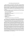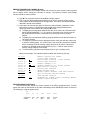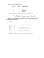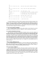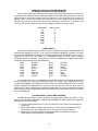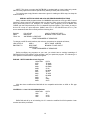
1
6800 ROM MONITOR
VERSON 1.0
USERS GUIDE
Southwest Technical Products Corporation
219 W. Rhapsody San Antonio, Texas 78116
Copyright 1977, Southwest Technical Products Corporation
Scanned and edited by Michael Holley Sept. 17, 2000 Revised Aug. 6, 2002
Southwest Technical Products Corporation Document Circa 1977
SWTPC SWTBUG® (SWATBUG) MONITOR ROM
One of the features of the SWTPC 6800 Computer System is that the conventional
programmer’s console has been replaced with a monitor ROM. The programmer’s console
consists of all the pretty switches and lights often found on similar microcomputers that are used
to bootstrap the system after power up. The programmer’s console not only raises the cost of the
system, but more often than not is confusing and tedious to use for both be-ginning and
experienced programmers. The monitor ROM on the other hand is a permanently stored program
that gives the computer the intelligence required to communicate with the operator thru an
interfaced terminal system immediately after power up without flipping switches for 10 minutes.
This technique makes the computer do the work of simplifying communication between itself and
the operator.
SWTBUG® is the name of the monitor program used in the SWTPC 6800 Computer
System. It might be thought of as kind of a mini-operating system since it gives the operator
command control over the computer system.
Features of the SWTBUG® ROM include:
∗
∗
∗
∗
∗
∗
∗
∗
∗
∗
Memory Examine and Change
Program loading from cassette or paper tape thru the control interface or thru I/O port # 0.
Program saving to cassette or paper tape
Go to user program
Display contents of registers
Erase SWTPC CT-1024 terminal system screen
SWTPC MF-68 floppy disk boot
Byte search
Breakpoint debugging
Vectored hardware and software interrupts to user defined addresses
SWTBUG® is a permanently stored program and cannot be erased or lost by either a loss of
power or user program error. It is always resident in the computer while power is ON and need
never be loaded into the machine. Subroutines within the ROM are documented and available to
the user to simplify programming and conserve on the use of user RAM memory. Character input
and output, string output and return to monitor are just a few subroutines available to the user.
SWTBUG® is a 1K byte program and is addressed high in memory, far above the amount of
RAM memory required for most user programs. Since SWTBUG® does require a small amount of
RAM memory for operation, a 128 byte scratchpad RAM has been implemented on the processor
board so that no external user RAM memory is required for monitor operation. There is even
enough extra room in this RAM so that short programs such as memory diagnostics can be
loaded into and run from the scratchpad RAM without requiring any external user RAM memory.
Extra care however must be exercised to avoid overstoring any memory locations required for
proper monitor operation. Complete de-tails on this are given later in this writeup. The
SWTBUG® ROM is located from memory addresses E000 thru E3FF. The scratchpad RAM is
located from memory addresses A000 thru A07F. Both components are physically located on the
processor board and are functional any time the system is powered up. Whenever computer
control is transferred from SWTBUG® to the user program, there are only four ways to get back
into the SWTBUG® command mode. The first is to put a jump to the CONTRL entry point
address within SWTBUG® as the last step of your program. The second is to incorporate a
command or action within your program which transfers program control to the CONTRL entry
point address within SWTBUG® The third is to depress the front panel RESET button. The fourth
is turn the computer OFF and then back ON again. The fourth method is rather drastic and wipes
out all RAM memory data, it is only mentioned to let you know that the computer always powers
up with the SWTBUG® monitor in the command mode.
1
SWTBUG® INSTALLATION
SWTBUG® is a MOS device and MOS integrated circuits are susceptible to damage by
static electricity. Although some degree of protection is provided internally within the integrated
circuits, their cost demands the utmost in care. Before opening and/or installing SWTBUG® you
should ground your body and all metallic tools coming into contact with the leads, thru a 1M ohm
¼ watt resistor. The ground must be an “earth” ground such as a water pipe, and not the circuit
board ground. As for connection to your body, attach a clip lead to your watch or metal ID
bracelet. Make absolutely sure that you have the resistor connected between you and the “earth”
ground, otherwise you will be creating a dangerous shock hazard. Avoid touching the leads of the
integrated circuits any more than necessary when installing it, even if you are grounded. Static
electricity should be an important consideration in cold, dry environments. It is less of a problem
when it is warm and humid.
When using SWTBUG® with an MP-A processor card, one board change is necessary since
SWTBUG® is a full 1 K ROM and MIKBUG® was a 1/2K device, If this ROM is replacing
MlKBUG, remove MIKBUG® from its socket. On the back side of the MP-A board you will notice
that pin 15 of IC-2 (ROM) is grounded. The land coming from pin 15 should be broken and a wire
added as shown below.
SWTBUG® should now be installed in the socket for IC-2. Be sure to orient the ROM
correctly when re-installing. The semicircle notch or dot should match with the MP-A board’s
component layout drawing. When installing SWTBUG® in the MP-A2 processor board no board
modifications are necessary. Follow the instructions supplied with the MP-A2 instruction set.
SWTBUG® OPERATION
The SWTBUG® firmware enables the computer to communicate with a terminal to perform
various programming and debugging functions. SWTBUG® will communicate with a terminal via
either a MP-C control interface or MP-S ACIA serial interface on I/O port 1. An optional MP-C
interface can be installed on I/O port 0 for punch and load functions. Although SWTBUG® is
essentially compatible with MIKBUG, be sure to read the COMPATIBILITY section before running
any programs written for MIKBUG. Below is a detailed description of each SWTBUG® command.
RESET
Upon receiving a RESET command, as during power up, SWTBUG® will initialize the
system to receive commands from a terminal. When the RESET button is pushed, control will
transfer to location E0D0 of SWTBUG®. The RESET button should be used for exiting loops or
malfunctioning programs. After resetting, the computer should respond with a carriage return, line
feed and a $ sign. At this point, SWTBUG® is waiting for commands. If breakpoints are being
used, the RESET function will not disable breakpoints. The BREAKPOINT function should be
referenced for additional information.
2
MEMORY EXAMINE AND CHANGE M (addr)
The Memory Examine and Change function can be used to enter machine code programs
and to display and/or change the contents of memory. The Memory Examine and Change
function should be used as follows:
1.) Type M. The computer should echo the M and output a space.
2.) Type in the four digit hexadecimal address that you wish to examine and/or change.
The computer should respond with a carriage return, line feed, $, the address and the
data that is stored at this address.
3.) At this point the user has the option of advancing, either forward or backward, to the
next memory location, or changing the data stored at the displayed address and
advancing to the next location or of exiting the M function.
a.) To display the next sequential address and data, a line feed or any character other
than 0123456789ABCDEF:;^=>? or a space or a carriage return may be entered.
Any leading spaces that are entered will be ignored by the memory change
function.
b.) To display the next sequential address going backward from the present location, a
^ should be entered.
c.) To change the data stored at the displayed location, enter the new data, either with
or without a leading space. If a non-hex value, such as a 3Q is entered the data will
remain unchanged and the memory change function will be exited. If the data is
unable to be changed (write protected memory, etc.) a ? will be output and the
memory change function will be exited.
d.) To exit the Memory Examine and Change function, type a carriage return.
Below is an example. The underlined parts are what was entered by the user.
$M 0100
$0100 00
$0101 BD
$0102 5D
$0103 C1
$0104 C9
$0105 15
$0104 23
$0105 15
$M 0105
$0105 15
$M E000
$E000 FE
$
.
.
.
01
23
^
.
3Q
56?
MEMORY LOCATION 0100 OPENED
DISPLAY NEXT LOCATION
DISPLAY NEXT LOCATION – SPACE IGNORED
DISPLAY NEXT LOCATION
CHANGE CONTENTS TO 01
CHANGE CONTENTS TO 23. SPACES IGNORED
READ PREVIOUS LOCATION
DISPLAY NEXT LOCATION
ENTER NON-HEX VALUE
SWTBUG CONTROL RESUMED. OPEN NEW LOCATION
EXIT BY HITTING CARRIAGE RETURN
OPEN ANOTHER LOCATION
ATTEMPTED TO CHANGE A WRITE PROTECTED MEMORY
SWTBUG CONTROL RESUMED
REGISTER DUMP FUNCTION R
The R command will display the current contents of the MPU's pushdown stack. “Current”
means the status of data stored on the stack immediately before SWTBUG® control is resumed.
The following is a typical register dump:
$R
$FF
16
23
17EC
0103
A042
$
CONDITION
CODES
ACC
B
ACC
A
INDEX
REG
PGM.
CTR.
3
STACK
PTR
The condition codes are as defined below:
BIT NO.
0
1
2
3
4
5
LABEL
C
V
Z
N
I
H
CONDITION CODE
Carry-borrow
Overflow
Zero
Negative
Interrupt mask
Half carry
In the above example the condition code of "3C" can be interpreted as follows:
3C16 =
0
BIT 7
0
BIT 6
1
BIT 5
1
BIT 4
1
BIT 3
1
BIT 2
0
BIT 1
0
BIT 0
Below are two examples of how the R command works. Assume that this small program was
entered to change certain registers.
$M 0100
$0100 CE
8E
LOADS STACK POINTER TO 100
$0101 12
10
$0102 34
00
$0103 86
CE
LOAD INDEX REGISTER WITH 1234
$0104 00
12
$0105 C6
34
$0106 FF
86
LOAD ACCUMULATOR A WITH 00
$0107 FD
00
$0108 08
C6
LOAD ACCUMULATOR B WITH FF
$0109 23
FF
$010A 67
7E
JUMP BACK TO SWTBUG CONTROL
$010B F7
E0
$010C 60
E3
$010D DD
AT THIS POINT THE STATUS WILL NOT BE PUSHED ON THE STACK
4
$R
$FF DC FC
$G
$R
$FF DC FC
$J 0100
$R
$FF DC FC
$M 010A
$010A 7E
$010B 50
$G
$F9 FF 00
$R
$F9 FF 00
$
$FF DC FC
6EFD 0100 A042
REGISTER DUMP BEFORE RUNNING PROGRAM
6EFD 0100 A042
NOTE R DUMP THE SAME AFTER RUNNING
6EFD 0100 A042
THE SAME AFTER A JUMP
AT THIS POINT THE JUMP TO SWTBUG CONTROL
IS REPLACED BY A SWI. NOTE THE VALUE
OF THE REGISTERS AFTER THE NEXT DUMP.
3F
1234 010A 0FF9
REGISTER DUMP GIVEN BY SWI
1234 010A 0FF9
DUMP SHOWS PROGRAM CHANGES
6EFD 0100 A042
R DUMP AFTER RESET
In the above program you will notice that the register dump after running the program is the
same as before even though the program contained statements that changed the processor’s
registers. The register dump did not reflect these changes because the new conditions were not
pushed on the computer’s stack. Note, however, the register dump did reflect the change when
the last instruction was a software interrupt -- a SWI instruction will push the processor’s status
on the stack and then display the contents of the registers.
CT-1024 CLEAR SCREEN COMMAND C
The C command outputs a home-up (1016) and an erase to end of frame (1616) control
characters for the clearing of the screen on a SWTPC CT-1024 or equivalent terminal system.
GO TO USER’S PROGRAM FUNCTION G
Upon entering a G command, SWTBUG® will transfer control to the user’s program by
executing a RTI (return from interrupt) instruction. This effectively causes the computer to jump to
the memory address stored in memory locations A048 and A049 in the SWTBUG® RAM. A048
contains the most significant byte and A049 the least significant byte of the memory address. If,
for example, you wish to execute a program starting at 0100, change A048 to a 01 using the M
function and change A049 to 00. Typing a G will then cause the computer to execute the program
whose starting address is 0100. Upon entering a program using the G function, the stack pointer
will be set at A049. The G function is also used to restart a program after a breakpoint has been
moved. In this case A048 and A049 should not be changed. See the Breakpoint section for
further information.
JUMP TO USER’S PROGRAM J(addr)
The J command will cause the computer to execute the program whose starting address is
given in the entered address. The J command does not look at locations A048 and A049. The
stack pointer will be set at A042 upon entering a program with a jump command. Example: J
0100. If a non-hex character is entered, SWTBUG® control will resume.
ASCII TAPE PUNCH COMMAND P
The P command provides a means for storing the contents of specified memory on either
cassette or paper tape. Normal output from the computer during a punch is thru either an MP-C
or MP-S serial interface on I/O port 1, but a MP-C interface on I/O 0 can be selected. (See the
description of the O command.) To use the P command, the upper and lower limits of the range
to be punched must first be stored in locations A002-A005 of the SWTBUG® RAM. If you wanted
to punch from addresses 0123 to 4567 (inclusive) you would use the memory examine and
change functions to set computer memory as follows.
5
A002 à
A003 à
A004 à
A005 à
01
23
45
67
MOST SIGNIFICANT BYTE OF LOWER ADDRESS
LEAST SIGNIFICANT BYTE OF LOWER ADDRESS
MOST SIGNIFICANT BYTE OF UPPER ADDRESS
LEAST SIGNIFICANT BYTE OF LOWER ADDRESS
Typing P would turn the punch on and output the specified memory data. A sample punch
output is as follows:
$M A002
$A002 02
01
MSB OF LOW ADDRESS
$A003 72
00
LSB OF LOW ADDRESS
$A004 EF
01
MSB OF HIGH ADDRESS
$A005 00
20
LSB OF HIGH ADDRESS
$A006 5F
$P
TAPE PUNCH COMMAND
S11301008E1000CE12348600C6FF3FE0E3DD005DB2
S11301108090E05160F73A8201F500FFC79771D1F2
S104012000DA
$
S1
13
0100
8E1000CE12348600C6FF3FE0E3DD005D
B2
START OF
BLOCK
CHARACTER
BYTE
COUNT
(HEX)
BLOCK
STARTING
ADDRESS
DATA
CHECK
SUM
The S1 at the start of the block is used to tell the load routine that valid punch data follows.
Each punch block must begin with the S1. The 1316 is the number of bytes that follow in the block.
In this case two bytes are required for the starting address of the block (01 and 00), 1016 bytes
are required for the data (8E 10 00 CE 12 34 86 00 C6 FF 3F E0 E3 DD 00 50) and one byte is
required for the checksum (B2). The checksum is generated by adding the complement of the
start of block address and the data, 8 bits at a time. At load-in time another checksum is
generated by the load routine which must match with the one generated at punch time.
As the punch begins a PUNCH ON (1216) control character will be output to the punch
device. If a MP-C control interface is the selected interface unused lines on the PIA will be
strobed to turn on the punch function of a SWTPC AC-30 or equivalent tape interface. (See the
PIA Strobing section for more information.) When the punch is completed a PUNCH OFF (1416)
control character will be output and another PIA line will be strobed. User control is then returned
to SWTBUG. To complete the tape making procedure you will have to enter the end of tape
command described below.
END OF TAPE COMMAND E
The E command will punch the contents of the program counter (A048-A049) and an S9 to
tape. The S9 is decoded by the load routine as an “end of tape” marker. For example, if you wish
to save a program that resides from 0000 to 000F and whose starting address is 0005 you would
perform the following sequence:
$M A002
$A002 FC 00
$A003 3E 00
$A004 A0 00
$A005 49 0F
$A006 4C
6
$M A048
$A048 01 00
$A049 03 05
$A04A F4
$P
$S11300000A0501001EF023FF01A01B351B37022443
$E
S105A04800050DS9
$
$
A048 and A049 are automatically transferred to A002-A005 and punched to tape by the E
command. A short delay follows the S9 to allow clean load-ins on cassette tape. Appropriate
punch on/off commands are automatically sent.
TAPE LOADER FUNCTION L
The L function is used to load either a MIKBUG® or SWTBUG® formatted program from
either paper or cassette tape. To use the L function, first set up the tape in the loading device and
type L. As with the punch command, a L function will load from an MP-S or MP-C on I/O port 1 or
if selected a MP-C on I/O port 0. A READER ON (1116) control character is output at the
beginning of the load and terminal echo is disabled. Again the PIA is strobed for use with a tape
interface. When the S9 end of tape marker is read, control will return to SWTBUG®. If a
checksum error is detected, a ? will be printed and control will return to SWTBUG® The load
routine verifies that the data being loaded is actually stored in the correct memory locations. If, for
some reason, a byte is not stored (bad memory, etc.) the computer will respond with a ?. To abort
the load function the RESET switch can be pressed. Before attempting to load a SWTPC binary
formatted tape, be sure to read the COMPATIBILITY section.
OPTIONAL PORT COMMAND O (not zero)
The O (not zero) command enables the user to load from or punch to a MP-C control
interface plugged on to port 0. To use the O command, type 0 followed by the desired option P, E
or L (punch, end of tape or load). The same rules apply for using the P, E and L functions as
described earlier. The O command will not support an ACIA type serial interface on port 0.
NOTE: When using a MP-C interface on port 0, a RESET will not, automatically turn off the
reader and punch as is done when installed on port 1. This makes it impossible to create or load
a binary formatted tape from an MP-C interface installed on I/O port 0 using existing binary load
and punch programs.
SOFTWARE BREAKPOINTS B(addr)
The B command enables the user to enter breakpoints (software interrupts) in a program for
debugging purposes. Breakpoints enable a program to be stopped at any point for register
examination, memory changing, etc. To use the breakpoint function, first load in your program
and set up A048 and A049 to the starting address of the program. Type B and then enter the
address where you want to set the first breakpoint. SWTBUG® will store the data that was at this
address and replace it with a 3F (software interrupt). Typing G for Go to User Program will start
program execution. When the program reaches the 3F, execution will stop and the processor’s
registers will be displayed. The B function can be used again to move the breakpoint to a new
location -- SWTBUG® automatically replaces the data at the old breakpoint location with the
original instruction. A G should be used to re-start the program -- do not reset A048 and A049 -SWTBUG® automatically pulls the restart location from the stack. To remove breakpoints, type B
followed by a carriage return. Breakpoints should always be removed in this way after using the
breakpoint function. If, while using breakpoints, the system is reset, the correct location on the
stack will be lost. After resetting, the program counter addresses (A048, A049) should be
reinitialized to the beginning of the program and execution restarted.
7
A previously set breakpoint will remain and may be changed or removed as described
earlier. If, when using the B command, a non-hex value is entered the previous breakpoint will be
removed and SWTBUG® control will resume.
There are several things that one must be aware of when using breakpoints to insure proper
operation.
1.) The breakpoint function uses the same locations as do vectored software interrupts;
therefore, vectored software interrupts should not be used with break points.
2.) The SWI jump location, A012, will be set to E124 when breakpoints are not in use, as
after power up, and will be set to E123 when breakpoints are in use. This location
serves as a pointer to tell the computer what to do when a 3F is seen. The RESET
button will not reset this location to the non-breakpoint state. The breakpoint-activated
state can only be exited by typing B followed by a carriage return. If you are using
breakpoints in a program that “bombs out” and you hit the RESET switch, you must
clear the present breakpoint before going on to another program. If this is not done
before a new program is loaded in, the first time the B command is used one byte of the
new program will be replaced by the stored byte from the last program.
3.) Do not set a breakpoint to an address where a breakpoint is already set. Doing so will
cause the computer to lose the original program data.
DO NOT
B 1377
G
B 1377
THIS IS OK
B 1377
B 0100
B1377
B carriage return
4.) The breakpoint routine uses SWTBUG® RAM locations A014-A016; therefore,
programs which use these three bytes should not be used in conjunction with
breakpoints.
DISK BOOT D
SWTBUG® contains the boot necessary to initialize a SWTPC MF-68 disk system. Typing D
will transfer control to the disk operating system, (if attached). If D is accidentally typed with no
disk attached, the RESET button must be pressed. Since the disk boot contains no error
detection, it may need to be typed more than once to do a boot.
JUMP TO PROM PROGRAM Z
Typing Z will transfer control to a program stored in PROM (if applicable) whose starting
address is at C000. Typing Z is equivalent of typing J C000
BYTE SEARCH F (high address) (low address) (byte)
The F (find] command will search memory from the specified low address to tile high
address, inclusive, and will display all memory locations containing the byte specified. For
example, to find all memory locations between 0100 and 0200 that contain 8E, the following
command should be used: F 020001008E. Note that no spaces may be used between addresses
and that the high address goes first.
$F 020001008E
If a non hex value is entered, SWTBUG® control will resume.
8
VECTORED SOFTWARE INTERRUPTS
Normally when encountering a SWI (3F) instruction, the computer will display the
processor’s registers and SWTBUG® control will be resumed. If desired, the 3F command can be
vectored to anywhere in memory, just like the NMI and IRQ interrupts. To use the vectoring
capability simply store the service routine address at location A012-A013 in the SWTBUG® RAM.
When a 3F is encountered, processor control will be transferred to the memory address stored in
A012-A013. Note: each time the system is RESET, A012 will be reset to the location of the
register dump routine. This means that any program which uses vectored SWl’s should set up
this location each time it is executed. If the location you wish to vector to is 10D0, for example,
the following statements at the beginning of the program will set up the vector correctly:
LDX # $10D0
LOAD VECTOR ADDRESS
STX $A012
STORE VECTOR
Vectored software interrupts should not be used in conjunction with breakpoints since the
breakpoint routine uses locations A012-A013.
VECTORED INPUT/OUTPUT
If desired, input and output can be vectored to a MP-S or MP-C interface on ports other than
#1. Locations A00A-A00B contains the port address that the subroutines INEEE and OUTEEE
use for inputting and outputting characters. To use vectored input/output your program must store
the desired I/O address in A00A–A00B before any I/O is done. Below is a list of I/O address
assignments for each port:
PORT
ADDRESS
0
8000
1
8004
2
8008
3
800C
4
8010
5
8014
6
8018
7
801C
The program statements that would set up the correct port would be as follows:
LDX #$8018
I/O on port 6
STX $A00A
Store
SWTBUG® will look at the port and will self-configure for either a MP-C or MP-S type
interface.
NOTE: Any time that SWTBUG‘s control sequence is initiated or when the RESET button is
pushed, the I/O address will be reset to port # 1. Therefore complete SWTBUG® monitor control
cannot be moved to another port.
USING NON-MASKABLE INTERRUPTS
Using non-maskable interrupts is very similar to using vectored software interrupts. A nonmaskable interrupt will occur whenever the NMI line on the computer’s bus is grounded either
through hardware or by an ACIA or PIA. When the NMI is seen, processor control will be
transferred to the location stored in A006 and A007. For example if an NMI service routine is
desired at location 1000 the following statements should be used at the beginning of your
program to set up the correct NMI jump address.
LDX #$1000
STX $A006
USING MASKABLE (IRQ) INTERRUPTS
Using regular maskable interrupts is the same as using non-maskable interrupts except that
when the IRQ line is grounded processor control will jump to the address stored in A000 and
A001. The computer will only respond to the interrupt if the processor’s interrupt mask bit 1 is 0. A
CLI instruction at the beginning of your program will insure this condition.
9
PIA STROBING
Use of the Control Interface for Read/Punch-On/Off Decoding
SWTBUG® software contains subroutines to send out pulses to unused pins of the PIA
integrated circuit on the MP-C serial control interface that can be used for automatic reader /
punch controls. These pulses can be used if you are using a SWTPC AC-30 cassette interface
and a terminal in which access to the control command decoding is denied.
If you intend to use the read/punch control logic output on the MP-C control interface board,
make the following connections from the indicated pins of ICI on the MP-C control interface board
to the specified pins of a twelve pin male connector shell. The connector pinning shown below is
correct for a SWTPC AC-30 cassette interface and will need modifications for other units. Be sure
to make the wires long enough to reach your AC-30 where the connector will be plugged. If you
have access to your terminal’s 16X baud rate clock, the terminal’s clock bus should be broken
and the 16X clock IN and OUT lines brought out to the same connector.
MP-C IC1 pin 7 (read on)
12 pin male shell female pin 1
MP-C IC1 pin 4 (punch on)
12 pin male shell female pin 2
MP-C IC1 pin 6 (read off)
12 pin male shell female pin 3
MP-C IC1 pin 5 (punch off)
12 pin male shell female pin 4
Terminal’s 16X clock OUT
12 pin male shell female pin 5
Terminal’s 16X clock IN
12 pin male shell female pin 6
MP-C ground
12 pin male shell female pin 12
These signals are low going pulses and are about 15 microseconds wide. They are not
buffered and should drive a maximum of only one standard TTL load.
PIA stroking will work only on SWTBUG®‘s L, P and E functions. Strobing is not supported
in BASIC and some other SWTPC software.
OPERATING THE MP-A2 PROCESSOR BOARD
AT BAUD RATES HIGHER THAN 1200 BAUD
The MP-S Serial Interfaces available for the SWTPC 6800 Computer System are capable of
operating at baud rates up to 9600 baud. Although baud rate clocks for 110, 150, 300, 600 and
1200 baud are generated, buffered and fed onto the mother board by IC4 of the MP-A2 board,
clocks for additional baud rates are also available from IC4 as well. The table below gives the
baud rate and respective output pin number of IC4.
BAUD RATE
MP-A2 IC4 pin
75
9
200
6
1800
15
2400
3
3600
16
4800
2
7200
17
9600
1
To use the selected clock, run an insulated jumper between the specified pin and pin 13 of
IC10 on the MP-A2 board. Run another insulated jumper between pin 12 of IC10 and either the
UD1 or UD2 bus connections points at the connector edge of the MP-A2 circuit board. IC10 is a
low power TTL buffer which must be inserted between the baud rate clock generator and the
mother board bus. Since user defined lines UD1 and UD2 are carried on just the 50-pin main
board bus and lines UD3 and UD4 are carried on just the 30-pin interface board, it will be
necessary to jumper two of the buses together to provide the selected baud rate clock on the
interface card bus. Each serial interface card to be operated with the selected baud rate clock will
have to be jumpered so its clock is acquired from the selected user defined line rather than one of
the five original baud rate clocks already present.
10
OPERATING THE MP-A PROCESSOR BOARD
AT BAUD RATES HIGHER THAN 1200 BAUD
When using the MP-S serial interface with an MP-A processor board, baud rate clocks for up
to 9600 baud are available from the baud rate generator on the MP-A processor board. The table
below shows the baud rates available and from which pin of IC4 on the MP-A board they are
derived. These 16X baud rate clocks are best feed back to the interface boards via the user
defined lines provided on the mother board. These baud rates of course are in addition to the
110, 150, 300, 600 and 1200 baud rate clocks already provided on the mother board.
BAUD RATE
75
200
1800
2400
3600
4800
7200
9600
MP-A IC4 pin
9
6
15
3
16
2
17
1
COMPATIBILITY
Although SWTBUG® has been written to be as compatible as possible with MIKBUG® and
with software supplied by SWTPC, it can never be completely MIKBUG® compatible. All major
subroutines of SWTBUG® are address and function compatible with MIKBUG®, but if you have a
program that enters into the middle of a MIKBUG® routine for some reason, program
modifications will be necessary. The following is a list of the MIKBUG® compatible subroutines
and strings along with their entry point addresses.
E040
LOAD19
E0C8
OUT4HS
E047
BADDR
E0CA
OUT2HS
E055
BYTE
E0D0
START
E075
OUTCH
E0E3
CONTRL
E078
INCH
E19C
MCLOFF
E07B
PDATA2
E19D
MCL
E07E
PDATA1
E1AC
INEEE
E0BF
OUT2H
E1D1
OUTEEE
If any doubt exists as to the compatibility of a particular program, it should be disassembled
and any references to memory locations E000–E1FF be verified. Since SWTBUG® is more
complex than MIKBUG, more RAM area must be used in the 6810 SWTBUG® RAM. If vectored
software interrupts and breakpoints are not being used, the area from A014 to A033 and from
A04A to A07F can be used for small, temporary programs such as memory diagnostics. Note that
some programs written for MIKBUG® use locations A034-A036 - these locations are not available
for use in SWTBUG®
LOADING BINARY TAPES THRU SWTBUG®
SWTBUG® was written to accept the binary formatted tapes supplied by SWTPC. These
tapes include 4K BASIC, 8K BASIC, CORES and DESEMBLER. When loading these tapes the
following rules must be followed:
1.) The tape reading device (AC-30, etc.) must be locked in the read on mode during the
binary load.
2.) Binary tapes must be loaded in thru port # 1, the control port. The optional load from
port 0 command is not supported in binary. You may load in ASCII however.
3.) When using a PIA type interface to load binary tapes, the unused lines used for
reader/punch on/off strobing are not activated.
11
NOTE: This does not mean that SWTBUG® is equipped with a binary loader-only certain
SWTPC binary tapes that contain a special binary loader (in ASCII) will work correctly.
To load the tape simply follow the instructions given for loading an ASCII tape, but keep the
reader locked on.
SPECIAL NOTES ON USING AN ACIA AND PROGRAM MODIFICATIONS
Many available 6800 programs written for MIKBUG® assume that a PIA type MP-C control
interface is being used and may address this port directly. When using an ACIA type interface,
these references need to be changed. For example, some programs, such as BASIC and
CORES, poll the PIA periodically to see if a character has been typed in. This is done in order to
kick out of a loop or a print sequence. (BASIC uses CTL..C. and CO-RES uses CTL..X.) The
source statements that do this usually take the following form:
B6 8004
2B 03
7E XX XX
LDA A PIAD
LOAD A FROM DATA REG.
BMI PRINT
BRANCH IF NOT CHAR. SEEN
JMP READY or RESTART
PRINT REMAINDER OF SEQUENCE
To change to a MP-S serial interface, this code can sometimes be replaced as follows;
LDA A PIAD à
ASR A
SEE IF CHAR. LOADED
BMI PRINT à
BCS PRINT
BRANCH IF CHAR. INPUT
JMP READY
PRINT REMAINDER OF SEQUENCE
Before modifying any programs on your own, you should have a working knowledge of
SWTBUG'S ACIA input routine, ACIA operation, and your particular program. The following is a
list of patches to some SWTPC supplied programs.
BLKJAK - SWTPC 6800 Black Jack Program
LOCATION
0270
0647
064A
064D
064F
0652
0654
0657
065A
065B
065D
DATA
7E 064A
7E 026D
B6 E008
27 08
B6 8004
2B F3
7E 0275
B6 8004
47
24EA
20 F5
With the above modifications BLKJAK will be compatible with either an ACIA or PIA type
interface.
CO-RES Ver. 1.0 and 1.01 ACIA Modifications
LOCATION
1682
1683
1685
DATA
47
24 02
20 A0
BASIC 8K and 4K up to an including Ver. 2.0 cannot be modified for ACIA operation. Later
versions should be purchased.
12
GENERAL RULES FOR PROGRAM WRITING
Although for a user program to be functional it need only work with the exact system it was
written for, following a few simple rules reduces program modifications for 6800 systems using
other monitors. Following these rules will make your programs more professional and versatile.
Some general guidelines are as follows:
1.) Minimize the number of references made to the ROM.
2.) Do not use strange, in-between SWTBUG® addresses. Generally only the routines
BADDR, BYTE, PDATA1, INHEX, OUT4HS, OUT2HS, CONTRL, INEEE and OUTEEE
should be used.
3.) For large programs, vector I/O through a jump instruction for ease of change to match
other I/O packages. Example:
DON’T
JSR INEEE
DO
JSR INPUT
à
JSR INEEE
JSR INPUT
à INPUT: JMP INEEE
JSR INEEE
JSR INPUT
à
4.) Try not to use the SWTBUG® RAM any more than necessary. With the exception of
using it as stack storage and memory diagnostics, there is no real reason to use the
SWTBUG® RAM area.
5.) Define the stack area at the beginning of the program. Example: Start LDS #$ A042.
Relocating the stack location to A042 at the beginning of each of your programs will
prevent you from having to reload the program counter addresses A048 and A049 each
time you RESET and restart your program.
6.) Most programs should have a provision for exiting them without hitting the RESET
button. A jump to CONTRL (7E E0E3) instruction in your program will cause
SWTBUG® control to resume when executed.
MEMORY DIAGNOSTICS
The earlier memory diagnostics ROBIT, MEMCON and CDAT supplied by SWTPC were
compatible only with MIKBUG®. The new versions ROBIT 2, MEMCON 3 and CDAT 2 are
compatible with both MIKBUG® and SWTBUG®.
PROGRAM DESCRIPTION
Although the source listing of SWTBUG® is well commented, the following subroutine by
subroutine description should be of use to those who wish to gain the maximum advantage of its
routines.
TEMPORARY STORAGE LOCATIONS
IRQ (A000)
This location is used by the standard IRQ interrupt request feature. When an
interrupt is generated, processor control will jump to the location stored in
IRQ.
BEGA (A002)
This location is where the beginning address is stored for the punch and end
of tape routines.
ENDA (A004)
This location is where the ending address is stored for the punch and end of
tape routines. It is also used by the byte search routine.
NMI (A006)
NMI is used by the non-maskable interrupt (NMI) function. When an NMI is
generated, processor control will jump to the location stored in NMI.
13
SP (A008)
Temporary storage location for the stack pointer. SP is used in the register
dump subroutines and by the breakpoint function.
PORADD (A00A)
This location contains the port address used for SWTBUG’s I/O routines.
PORECH (A00C)
This byte tells SWTBUG® ‘s input routines whether or not to echo.
XHI (A00D)
Temporary index register storage used by numerous routines.
XLOW (A00E)
Temporary index register storage used by numerous routines.
XTEMP (A010)
Temporary index register storage for input and output routines.
SWIJMP (A012)
When a SWI instruction is encountered, processor control will transfer to the
location stored in SWIJMP.
BKPT (AQ14)
Temporary breakpoint address storage.
BKLST (A016)
Temporary data storage for the breakpoint routine.
TW (A044)
Temporary storage location for load/punch.
TEMP (A046)
Temporary storage location for punch and load.
BYTECT (A047)
Temporary storage location for load/punch.
SWTBUG® SUBROUTINE AND TEXT STRING DESCRIPTION
IRQV (E000)
This is the entry point for regular IRQ interrupts. Processor control is given of
the service routine whose address is stored in IRQ.
JUMP (E005)
This is the service routine for the J command. BADDR is used to input the
address and a jump then occurs to the correct address.
CURSOR (E009)
Home-up and erase to end of frame characters for CT 1024.
LOAD (E00C)
Load is the ASCII loading routine. Load uses a number of other SWTBUG®
subroutines.
BADDR (E047)
BADDR is a subroutine to input a 4-digit hexadecimal number, such as 137D,
from the control terminal. BADDR uses the subroutines BYTE, INCH and
INHEX and uses temporary storage locations XHI, XLOW, CKSM, both
accumulators and the index register. When BADDR is called it will look for
four hex numbers to be entered from the terminal. If a non-hex value, such
as H, is entered, SWTBUG® control will resume. If all characters entered are
valid hex, the results will be stored in XHI, XLOW and the index register.
Accumulator A will contain of XLOW. If 137D is entered the results will be as
followsACC A
7D
ACC B
CKSM
IXR
137D
XHI
13
XLOW
7D
-
CKSM and ACC B are used internally to generate a check sum for the
PUNCH routine.
BYTE (E055)
BYTE is similar to BADDR, but inputs only two hex characters from the
terminal to generate one 8-bit byte equivalent. BYTE uses the subroutines
14
INHEX and INCH, temporary storage locations CKSM and both
accumulators. If a non-hex value is entered, SWTBUG® control will resume.
When BYTE is called as a subroutine, the computer will wait for two hex
characters to be entered thru the control port. If a 3C is entered, the results
will be as follows:
ACC A
3C
ACC B
CKSM
IXR
UNCHANGED
CKSM
Prior CKSM + check sum generated inside
BYTE
OUTHL (E067)
OUTHR (E06B)
These subroutines are used by OUT2HS and OUT4HS to output
hexadecimal numbers
OUTEEE
OUTCH
OUTEE
(E1D1)
This is the character output routine used by PDATA1, OUT4HS, OUT2HS
and most programs written for SWTBUG/MIKBUG® to output one character
from the computer to the control port (I/O # 1). OUTEEE, OUTCH and
OUTEE1 are all functional equivalents- OUTEE1 is the main output routine
with OUTCH and OUTEEE being jumps to OUTEE1. When using this
routine, OUTEEE (E1D1) should be used to maintain compatibility with
MIKBUG® systems.
To use OUTEEE the character to be output should be placed in the A
accumulator in its ASCII form. To output the letter A on the control terminal,
the following program could be used.
LDA A
#$41
JSR
OUTEEE
The processor’s registers are affected as follows.
ACC A
changed internally
ACC B
not affected
IXR
not affected
OUTEEE is an 8-bit output routine and does not generate a parity bit.
INEEE,
INCH,
INEEE1
(E1AC)
The locations are all functionally equivalent to SWTBUG® ‘s character input
routine. This routine will look for one character from the control terminal (I/O
# 1) and store it in the A accumulator. Once called, INEEE will loop within itself until a character has been input. Anytime input is desire, the call JSR
INEEE should be used.
INEEE automatically sets the 8th bit to 0 and does not check for parity.
When using INEEE the processor’s registers are affected as follows:
ACC A
loaded with the character input from the terminal
ACC B
not affected
IXR
not affected
INCH8 (E1F6)
INCH8 is functionally the same as INEEE except that the 8th bit is not set to
8. This subroutine should be used whenever full 8-bit input is desired, such
as in binary loader programs.
INHEX (E0AA)
INHEX is the subroutine used by BYTE and BADDR that will input one
hexadecimal character from the control terminal. If a non-hex character is
entered, SWTBUG® control will resume. If a hex character, such as an E is
entered, the results will be as follows:
ACC A
0E
ACC B
not affected
IXR
not affected
PDATA1 (E07E)
PDATA1 is the subroutine used to output a string of text on the control
terminal. PDATA1 will start outputting data that is pointed to by the index
register and will continue until a 04 is seen. For example, if you wanted to
print HELLO on the terminal the following could be used.
15
START
TEXT
ORG $100
LDX #TEXT
JSR PDATA1
JMP CONTRL
FCB $0D, $0A
FCC /HELLO/
FCB 4
END
-
The accumulator and register status after using PDATA1 is as follows:
ACC A
Changed during the operation
ACC B
UNCHANGED
IXR
Contains the memory location of the 04
CHANGE (E088)
CHANGE is SWTBUG‘s memory examine and change function. Change
uses a number of other SWTBUG® subroutines.
OUT4HS (E0C8)
OUT4HS is used to output a four-digit (16-bit) hexadecimal number onto the
control terminal. The address of the most significant byte to be output should
be loaded into the index register before calling OUT4HS. For example, to
out-put the 16-bit hex number stored in memory locations 1000 and 1001
whose most significant byte is in 1000 while the least significant byte is in
1001 the following sequence should be used:
LDX # $1000
JSR OUT4HS
-
If location 1000 contained a hex 3C and 1001 contained a hex 0B, an ASCII,
3C0B would be displayed on the screen when OUT4HS is called. Remember
memory data is handled in hex but must be output as ASCII characters which
have a different hex value than those stored in the computer’s memory. The
registers are affected as follows:
ACC A
Changed during the operation
ACC B
UNCHANGED
IXR
Incremented by two. (1002 in this example)
OUT2HS (E0CA)
OUT2HS is similar to OUT4HS, but outputs only two hex characters (one
byte). For example, to display the byte stored at 2008 the following sequence
would be used:
LDX # $2000
JSR OUT2HS
-
An ASCII 6C would be output to the control terminal if location 2001
contained a hex 6C. The registers are affected as follows:
ACC A
Changed during the operation
ACC B
UNCHANGED
IXR
Incremented by one. (1001in this example)
OUTS (E0CC) OUTS is a subroutine that outputs one space to the control terminal.
START (E0D0)
START is the beginning of a sequence of steps that initialize the system
during power up or reset. First, the stack pointer is set to be A042 and is
stored in SP. Next, an FF is stored in location A943. This sets the interrupt
mask bit in the stack so that when a G command is given the processor will
not respond to interrupts until told to do so. The type of port being used
(ACIA or PIA) is then determined by initializing it as a PIA and looking to see
if this worked. If not, an ACIA is assumed and the proper ACIA initialization
routine, AL2, is selected. The program then goes to CONTRL sequence.
16
CONTRL (E0E3)
This MIKBUG® equivalent sequence again resets the stack to A042.
PORECH is cleared to enable echo and the subroutine SAVGET is selected
to get the correct port number and type. Next, the routines PNCHOF and
RDOFF generate punch and reader off commands. A carriage return, line
feed, erase to end of line (1516) and a $ is then output to the control terminal.
At this point SWTBUG® is ready for command input.
SFEl (E124)
SFEl is the entry point for non user-vectored software interrupt instructions. If
vectored software interrupts are selected, a jump is executed to the proper
location. If breakpoints are in use the stack pointer is not changed, the
processor’s registers are displayed and SWTBUG® is instructed to look for
the next command. If neither breakpoints or vectored software interrupts are
selected a register dump occurs and the CONTRL sequence is initiated.
PRINT (E130)
PRINT is the routine that actually does the dumping of the processor’s
registers.
LOOK (E173)
LOOK is the routine that inputs a character from the terminal and jumps to
the appropriate location in SWTBUG® if it is a valid command.
SFE (E18B)
Entry point for software interrupt instructions.
S9 (E190)
S and 9 string for the end of tape routine.
MTAPE1 (E193)
This is the character string containing a carriage return, line feed, erase to
end of line, four nulls, a S1 for tape control and 04 for PDATA1 control.
MCL (E19D)
This string contains a carriage return, line feed, three nulls, a $ and a 04 for
PDATA1 control.
E1A5 (E1A5)
E1A5 is a special entry location which is used by the binary load routine on
some SWTPC binary tapes.
NMIV (E1A7)
This routine fetches the correct jump location for a NMI.
SEARCH (E1AE)
Byte searching routine.
GOTO (E1D0)
GOTO contains the RTI instruction that is used by the G command to
execute a user program.
SAVGET (E1D3)
This routine saves the index register in XTEMP and tests for the appropriate
interface location and type. The index register is then loaded with the
address of this interface.
ISACIA (E1D9)
ISACIA is the routine that sees if an ACIA or PIA is present.
BILD (E1F3)
BILD is a special sequence of increment stack pointer instructions used only
by the binary loader on some SWTPC binary tapes.
ACIAIN (E1FF)
This is the ACIA input routine. PORECH is polled for the desired echo/don’t
condition. The character in the A accumulator is then output, the index
register and B accumulator restored and an RTS instruction executed by the
RES routine.
ACIOUT (E212)
This is the ACIA output routine which outputs the character in the A
accumuator, and recovers the B accumulator and index register.
IN1 (E223)
IN1 is the PIA input routine which inputs a character from the control terminal
and stores it in the A accumulator. The correct echo/non echo condition is
selected and the B accumulator and index register are restored.
17
IOUT (E240)
IOUT is the PIA output routine which outputs the character in the A
accumulator.
OPTL (E269)
OPTL is the service routine that sets up PORECH for I/O on port 0. The
appropriate command P, E or L is then selected.
PIAECH (E27D)
This routine disables the echo on a PIA type interface.
PIAINI (E284)
This routine is used to initialize PIA type interfaces.
DELAY (E202)
DELAY is a general purpose delay loop. If desired, the index register can be
pre-loaded with a number other than FFFF for shorter delays. The entry point
in this case is DELAY1 (E2C5).
CLEAR (E2CC)
This routine generates a home up, erase to end of frame command for
SWTPC CT 1024 and similar terminal systems.
BREAK (E2D9)
BREAK is the routine that is used to enter software breakpoints. First, the address is input by BADDR. If breakpoints were previously in use the data is
replaced at the previous breakpoint address and the new breakpoint is
inserted.
PNCHS9 (E31E
This routine selects A048 and A049 as the beginning and ending address for
the punch routine and punches their contents. A S9 is then punched to tape
followed by a short delay.
RDON (E334)
RDOFF (E347)
PNCHON (E34D)
PNCHOF(E353)
These subroutines are used to turn a reader/punch on and off. At the
beginning of each routine the A accumulator is loaded with the ASCII value
of the particular function that is normally decoded by a Teletype or other
terminal system. The B accumulator is then loaded with a special bit pattern
that will cause a predetermined line to be toggled on PIA type interfaces.
ACC A is then out-put using OUTEEE and if a PIA type interface is being
used the proper PIA line is strobed by the STROBE routine. The proper line
is determined by the con-tents of ACC B. The subroutine RDON also clears
the location PORECH and re-configures PIA type interfaces to be sure that
the echo function of the character input routine is disabled. Both
accumulators and the index register are used and are not retained.
ACC A
ACC B
FUNCTION
11
20
Reader ON
13
10
Reader OFF
12
04
Punch ON
14
08
Punch OFF
STROBE (E357)
This is the routine that actually generates the pulses on the unused lines of a
PIA type interface for reader/punch control.
PUNCH (E376)
PUNCH is the ASCII punching routine of SWTBUG, PUNCH consists of
several parts and uses various SWTBUG’s subroutines.
TABLE (E3D1)
This is the command table used by the lookup routine. The table is arranged
in three byte blocks. The first byte is the ASCII value of the command. The
next two bytes are the address of the routine that will service the command.
SVVTBUG is a registered trademark of Southwest Technical Products Carp
MlKBUG is a registered trademark of Motorola Inc.
Teletype is a registered trademark of Teletype Corp.
18