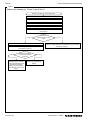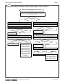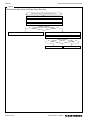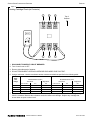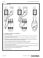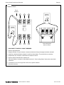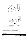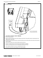
1
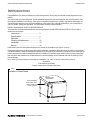
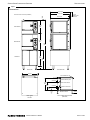
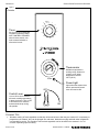
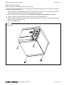
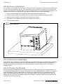
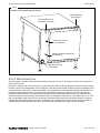
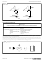
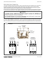
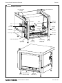
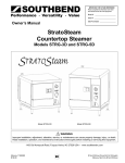
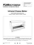
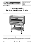
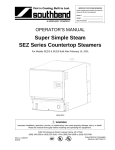
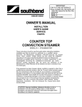
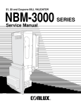
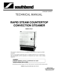
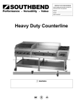
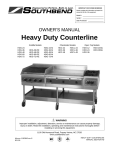
IMPORTANT FOR FUTURE REFERENCE
Please complete this information and retain
this manual for the life of the equipment:
Model #: __________________________
Serial #: __________________________
Date Purchased: ___________________
Owner’s Manual
StratoSteam
Countertop Steamer
Models STRE-3D and STRE-5D
Model STRE-3D
Model STRE-5D
WARNING
Improper installation, adjustment, alteration, service, or maintenance can cause property damage, injury, or death.
Read installation, operation, and maintenance instructions thoroughly before installing or servicing this equipment.
1100 Old Honeycutt Road, Fuquay-Varina, NC 27526 USA • www.southbendnc.com
MANUAL 1185184
$18.00
STRATOSTEAM COUNTERTOP STEAMER
MANUAL SECTION STRATOSTEAM
SAFETY PRECAUTIONS
STRATOSTEAM COUNTERTOP STEAMER
SAFETY PRECAUTIONS
Before installing and operating this equipment, be sure everyone involved in its operation is fully trained and aware of
precautions. Accidents and problems can be caused by failure to follow fundamental rules and precautions.
The following symbols, found throughout this manual, alert you to potentially dangerous conditions to the operator,
service personnel, or to the equipment.
DANGER
This symbol warns of immediate hazards that will result in severe injury or death.
WARNING
This symbol refers to a potential hazard or unsafe practice that could result in injury or
death.
CAUTION
This symbol refers to a potential hazard or unsafe practice that could result in injury,
product damage, or property damage.
NOTICE
This symbol refers to information that needs special attention or must be fully understood,
even though not dangerous.
WARNING
FIRE HAZARD
FOR YOUR SAFETY
Do not store or use gasoline or other flammable vapors and liquids in the vicinity of cooking appliances.
Keep area around cooking appliances free and clear of combustibles.
WARNING
BURN HAZARD
Contact with hot surfaces will cause severe burns. Always use caution when operating cooking appliances.
Stand back when opening the steamer door as hot steam or hot water may escape from the door opening.
Hot steam or hot water will flow out the drain located at the right rear bottom corner of the steamer.
Hot steam may escape from the pressure relief valve located at the top left rear corner of the steamer.
WARNING
ELECTRIC SHOCK HAZARD
Disconnect the power to the appliance before cleaning. Do not remove panels that require tools to remove.
NOTICE
Southbend appliances are intended for commercial use only. Not for household use.
Warranty will be void if service work is performed by other than a qualified technician, or if other than genuine
Southbend replacement parts are installed.
Give this Owner’s Manual and important papers to the proper authority to retain for future reference.
Copyright © 2004 by Southbend. All rights reserved. Published in the United States of America.
PAGE 2 OF 48
OWNER’S MANUAL 1185184
STRATOSTEAM COUNTERTOP STEAMER
INTRODUCTION
INTRODUCTION
Congratulations! You have purchased one of the finest pieces of heavy-duty commercial cooking equipment on the
market.
You will find that your new equipment, like all Southbend equipment, has been designed and manufactured to meet
the toughest standards in the industry. Each piece of Southbend equipment is carefully engineered and designs are
verified through laboratory tests and field installations. With proper care and field maintenance, you will experience
years of reliable, trouble-free operation. For best results, read this manual carefully.
RETAIN THIS MANUAL FOR FUTURE REFERENCE.
This manual is for Southbend StratoSteam Countertop Steamer models STRE-3D and STRE-5D. The manual is
divided into six sections:
Introduction ............................................3
Specifications.........................................4
Operation ...............................................7
Cleaning & Maintenance........................10
Installation..............................................12
Service...................................................19
Each steamer has two serial plates located on the exterior of the steamer (see Figure 1 below).
Read these instructions carefully before attempting installation. Installation and initial startup should be performed by
a qualified installer. Unless the installation instructions for this product are followed by a qualified service technician (a
person experienced in and knowledgeable with the installation of commercial gas and/or electric cooking equipment)
then the terms and conditions on the Manufacturer’s Limited Warranty will be rendered void and no warranty of any
kind shall apply.
In the event you have questions concerning the installation, use, care, or service of the product, write to:
Southbend
1100 Old Honeycutt Road
Fuquay-Varina, North Carolina 27526 USA
Figure 1
Location of Serial Plates
Main Serial Plate
(all information)
Second Serial Plate
(model number, serial
number, voltage, and
number of phases)
OWNER’S MANUAL 1185184
PAGE 3 OF 48
SPECIFICATIONS
STRATOSTEAM COUNTERTOP STEAMER
SPECIFICATIONS
NOTICE
Local codes regarding installation vary greatly from one area to another. The National Fire Protection Association,
Inc., states in its NFPA 96 latest edition that local codes are the “authority having jurisdiction” when it comes to
installation requirements for equipment. Therefore, installations should comply with all local codes.
The steamer, when installed, must be electrically grounded and comply with local codes, or in the absence of local
codes with the National Electrical Code ANSI/NFPA 70-latest edition.
Canadian installations must comply with CSA-Standard (C22.2 No. 109-M1981 General Requirements-Canadian
Electrical Code, Part II. 109-M1981) Commercial Cooking Appliances.
Southbend reserves the right to change specifications and product design without notice. Such revisions do not
entitle the buyer to corresponding changes, additions, or replacements for previously purchased equipment.
This product is intended for commercial use only, not for household use.
CLEARANCES
WARNING
MINIMUM CLEARANCES FROM COMBUSTIBLE CONSTRUCTION
Minimum clearance from combustible and non-combustible surfaces is 0" on the sides, bottom, and top; and 4" on
the rear. Adequate clearance must be provided in the aisle in front of the steamer to permit operation (including
pulling out of pans).
Steam may escape from the pressure relief valve at the top left rear corner of each steamer, and from the door
opening when the door is opened. Installation under a vented hood is recommended.
A steamer may be installed on combustible and non-combustible countertops.
DIMENSIONS
The dimensions of the steamer are shown in Figure 2 on the next page. The following table lists the interior
dimensions and the crate dimensions and weight.
Model
STRE-3D
STRE-5D
Interior Dimensions
Width
Depth
Height
13-1/2"
24"
10-5/8"
(343)
(610)
(270)
13-1/2"
24"
15-5/8"
(343)
(610)
(397)
Pan Capacity*
1"
2.5"
4"
6
3
2
11
5
3
Width
52"
(1321)
52"
(1321)
Crate Dimensions
Depth
Height
43"
40"
(1092)
(1016)
43"
40"
(1092)
(1016)
Volume
51.8 cu. ft.
1.47 cu. m.
51.8 cu. ft.
1.47 cu. m.
* “Pan Capacity” is the number of 1", 2.5", or 4" high standard pans (12" wide x 20" front-to-back) that the steamer will hold.
PAGE 4 OF 48
OWNER’S MANUAL 1185184
Crated
Weight
216 lbs.
98 kg.
238 lbs.
108 kg.
STRATOSTEAM COUNTERTOP STEAMER
SPECIFICATIONS
Figure 2
Dimensions
32-3/4" (832)
29-3/4" (756)
Dimensions shown in inches and (millimeters)
3/4"
(19)
28-3/4" (730)
4" (102)
Minimum Rear
Clearance
19-1/2"
(495)
Model STRE-3D
24-1/2"
(622)
Model STRE-5D
73-3/4"
(1873)
Cabinet Base
23"
(584)
29"
(737)
6" (152)
FRONT VIEW
RIGHT SIDE VIEW
24" (610)
Pressure-Relief Vent
3" (76)
Electric Cable Entry Hole
3-3/4" (95)
17-3/4"
(451)
Water Inlet Connection
12-3/4"
(324)
5-1/4"
(133)
3-1/2" (89)
1-1/4"
(32)
TOP VIEW
OWNER’S MANUAL 1185184
Drain Box Overflow Vent
1-3/4" (44)
Drain Connection
4" (102)
UTILITY CONNECTIONS AND VENTS
(REAR VIEW)
PAGE 5 OF 48
SPECIFICATIONS
STRATOSTEAM COUNTERTOP STEAMER
ELECTRICAL REQUIREMENTS
One fused electrical connection is required to the contactor of each steamer. All steamers are shipped per customer
order, three phase or single phase. (A kit is available for field conversion to three phase or single phase.) The fused
connection must be wired for the required voltage and maximum amperage as listed in the chart below:
Voltage
Total Connected Amps
Model STRE-3D
Model STRE-5D
1 Phase
3 Phase
1 Phase
3 Phase
208 V 60 Hz
44
26
53
31
220 V 50/60 Hz
41
24
51
29
240 V 60 Hz
38
22
46
27
480 V 60 Hz
19
11
23
14
WATER REQUIREMENTS
To meet warranty requirements, the water supply must be as follows:
Connection
Pressure
Total Dissolved Solids (TDS)
Hardness
pH
Maximum Fill Capacity
1/4" compression, cold water
30 to 60 PSI
60 PPM or less
2 grains (35 PPM) or less
7.0 to 7.5
0.87 gallons
Typical usage is 0.46 gallons per minute at 45 PSI.
In order to minimize service problems and to meet the warranty requirements, a water treatment system (softener) is
recommended when water quality does not meet the limits stated above.
DRAIN REQUIREMENTS
The drain outlet has a 1" NPT female connector. Do NOT directly connect the drain to a plumbing system unless you
also install an “open funnel” downstream of this connection (see Figure 7 on page 16). There must be no back-flow or
back-pressure into the drain connection!
PAGE 6 OF 48
OWNER’S MANUAL 1185184
STRATOSTEAM COUNTERTOP STEAMER
OPERATION
OPERATION
NOTICE: WATER SPECIFICATION
To meet warranty requirements, supply water must meet the following specification:
Total Dissolved Solids (TDS)............60 PPM or less
Hardness...........................................2 Grains (35 PPM) or less
pH Factor ..........................................7.0 to 7.5
STARTUP
Turn control lever to “ON” position (see Figure 3). The steamer will fill automatically and be ready for cooking in about
four minutes.
OPERATION
CAUTION
HOT STEAM WILL ESCAPE WHEN DOOR IS BEING OPENED. TO PREVENT BURNS KEEP HANDS AND
FACE AWAY FROM STEAM.
When turned ON, the steamer operates continuously. To save water and electricity, turn the control lever to OFF
when the steamer is not in use.
Suggested cooking times for various foods are shown in the table in the following section.
Pan specifications are shown on page 4.
The door may be opened or closed at any time. The steamer temporarily shuts off while the door is open.
Timer can be used as a reminder to the operator. The timer does NOT turn the steamer on or off!
SHUTDOWN
Turn lever to the “OFF” position. The water in the bottom of the cavity will automatically drain.
TROUBLESHOOTING BY OPERATOR
The following table lists the possible causes and solutions of problems that may occur during operation.
Problem
Possible Causes and Solutions
Steamer does not heat up at all.
– Electric power is shut off. Turn on power.
– Water supply is shut off. Turn on water.
– Not enough water is entering steamer. Check water supply.
– Lime build-up. De-lime steamer cavity (see page 10).
– If water is OK and there is little lime build-up, call repair service.
Steamer does heat up, but does not produce enough steam.
– Door is open or ajar. Close steamer door completely.
– Lime build-up. De-lime steamer cavity (see page 10).
– Not enough water. Check water supply.
Steamer does not drain correctly.
– Clogged drain on inside of steamer cavity. Check and clear.
– Clogged drain outside of steamer. Check and clear.
OWNER’S MANUAL 1185184
PAGE 7 OF 48
OPERATION
STRATOSTEAM COUNTERTOP STEAMER
Figure 3
Controls
TIMER
OFF 0
5
10
60
Timer
Set for up to 60 minutes as a
reminder to operator. DOES
NOT CONTROL STEAMER.
When buzzer sounds, turn
knob counterclockwise to
silence the buzzer.
15
55
20
50
25
45
40
160
140
120
100
80
40
30
35
180 190
200
210
80 90
70
100
60
105
50
40
110
20
115
0
°C
°F
Thermometer
220
Indicates temperature in
cooking cavity. Steamer is
“ready to cook” when
temperature reaches
190°F (88°C).
230
240
Power
Power Light
Lights when the steamer has
electric power and Control
Lever is turned to ON.
OFF
Control Lever
Turn to ON to cook. Steamer
will reach cooking temperature
in about 4 minutes. Turn to OFF
to shut down or to conserve
water and electricity during
idle periods.
ON
COOKING TIPS
•
Schedule cooking of fresh vegetables so that they will be served soon after they are cooked. If it is necessary to
prepare them in advance, they can be plunged into cold water, drained thoroughly and held under refrigeration
until needed for service. Five pounds of cold cooked vegetables can be reheated in the steamer in 5 to 10
minutes, depending upon the variety.
PAGE 8 OF 48
OWNER’S MANUAL 1185184
STRATOSTEAM COUNTERTOP STEAMER
OPERATION
•
To avoid green yolk (which is a deposit of iron sulfide) chill the eggs immediately after removing from the
steamer by plunging them into a cold water bath (preferably containing ice).
•
A quick and easy way to cook eggs for a salad mixture is to crack them directly into a solid steam table pan
which has been lightly coated with salad oil. Do not mix. Steam until they are hard cooked. Remove and chop as
you would for egg salad. The job of peeling is eliminated.
•
Chicken, sausage, and/or fish may be browned in an infra-red or radiant broiler after steaming by brushing with
melted margarine mixed with salad oil to give a golden brown color.
•
Save juices from steamed meat and poultry to make soups, sauces, or casserole dishes.
•
Chicken may be steamed in advance and then refrigerated. Bring food back to 180°F before serving.
•
Steaming brisket is a definite time saver. Boiling in water takes 40 to 50 minutes per pound. Using the steamer
can save 50% in cooking time.
•
Steamed cabbage retains its color and wedge identity. It will not break apart as it does when boiled.
•
When removing items prepared in a perforated pan, place a solid pan underneath the perforated pan with the
cooked food in order to prevent dripping on the floor.
•
The steamer is designed to accept standard 12" x 20" pans. Fractional size pans and dishes can be used as
well with a perforated shelf.
•
For stirring, the pan does not have to be removed from the steamer. Pull pan 1/3 way out of the cavity and the
entire surface is accessible.
•
The door may be opened at any time during operation to remove or add food. While the door is open, the
steamer will stop producing steam.
SUGGESTED COOKING TIMES
These cooking times are for general guidance only. Differences in food quality, size, shape, thickness, freshness, load
size, and desired degree of doneness must be taken into consideration and adjustments made in time, if necessary.
Quantity
STRE-3D Cooking
Time (minutes)
STRE-5D Cooking
Time (minutes)
18
48
5
6
6
7
Potatoes, Red
4 lbs.
8 lbs.
18
18
18
18
Rice
2 lbs.
3 lbs.
15
15
16
17
Shrimp, Frozen
2.5 lbs.
8 lbs.
4.5
8
4
7
Corn, Frozen
2.5 lbs.
7.5 lbs.
3
5
2.5
4.5
Peas, Frozen
5 lbs.
12 lbs.
5.5
10
4
8
2.5 lbs.
8 lbs.
15 lbs. (3 full pans)
25 lbs. (5 full pans)
4
6.5
14
-
3.25
5.5
17
1 piece
8 pieces
7
7
7
7
8 pieces
18 pieces (3 full pans)
30 pieces (5 full pans)
12
17
-
10
15
Lasagna, 6 lb., Frozen
1
3
5
65
65
-
60
60
Cake, White, 5 lb. Mix
1 pan
30
25
Product
Eggs
Mixed Vegetables, Frozen
Salmon Filets, Frozen, 4.5 oz.
Salmon Filets, Frozen, 6 oz.
OWNER’S MANUAL 1185184
PAGE 9 OF 48
CLEANING & MAINTENANCE
STRATOSTEAM COUNTERTOP STEAMER
CLEANING & MAINTENANCE
WARNING
Shut off the steamer before cleaning or performing maintenance.
Southbend appliances are sturdily constructed of the best materials and are designed to provide durable service when
treated with ordinary care. To expect the best performance, your equipment must be maintained in good condition and
cleaned daily. Naturally, the periods for this care and cleaning depend on the amount and degree of usage.
Following daily and periodic maintenance procedures will enhance long life for your equipment. Climatic conditions
(such as salt air) may require more thorough and frequent cleaning or the life of the equipment could be adversely
affected.
Keep exposed, cleanable areas clean at all times.
DAILY CLEANING AND MAINTENANCE
NOTICE
DO NOT USE high-chlorine or bleach solution for cleaning the door gasket.
DO NOT USE steel wool or other metallic pads in the steamer.
1. Turn control lever to “OFF” and allow time for the steamer to drain and cool.
2. Remove and clean pans.
3. Remove and clean pan supports and cavity bottom cover. Wash separately in a sink with a mild detergent and
warm water. Dry thoroughly with a clean cloth. Non-metallic scouring pads may be used to remove cooked-on
deposits.
4. Clean all interior surfaces with mild detergent, warm water, and a non-metallic pad. If discoloration of surfaces
starts due to buildup of seasonings or food products, remove them using a non-metallic scouring pad. RINSE
THOROUGHLY WITH CLEAN WATER. Dry thoroughly with a clean cloth.
5. Ensure drain opening inside of cavity is clear.
6. Clean drain opening.
7. Place cleaned cavity bottom cover, pan supports, and pans back into their correct positions.
8. Leave the door open at night after cleaning to allow complete drying and to prolong the life of the door gasket.
PERIODIC DE-LIMING (AS NEEDED)
If lime or mineral deposits start to buildup on the cavity interior, they should be removed with a non-caustic de-liming
solution such as Lime-A-Way®. Follow the manufacturer’s instructions for use of the de-liming solution.
STAINLESS-STEEL SURFACES
To remove normal dirt, grease and product residue from stainless steel surfaces that operate at LOW temperature,
use ordinary soap and water (with or without detergent) applied with a sponge or cloth. Dry thoroughly with a clean
cloth.
To remove BAKED-ON grease and food splatter, or condensed vapors; apply cleanser to a damp cloth or sponge and
rub cleanser on the metal in the direction of the polishing lines on the metal. Rubbing cleanser, as gently as possible,
in the direction of the polished lines will not mar the finish of the stainless steel. NEVER RUB WITH A CIRCULAR
MOTION. Soil and burnt deposits which do not respond to the above procedure can usually be removed by rubbing
the surface with SCOTCH-BRITE scouring pads or STAINLESS scouring pads. DO NOT USE ORDINARY STEEL
WOOL as any particles left on the surface will rust and further spoil the appearance of the finish. NEVER USE A
WIRE BRUSH, STEEL SCOURING PADS (EXCEPT STAINLESS), SCRAPER, FILE OR OTHER STEEL TOOLS.
PAGE 10 OF 48
OWNER’S MANUAL 1185184
STRATOSTEAM COUNTERTOP STEAMER
CLEANING & MAINTENANCE
Surfaces which are marred collect dirt more rapidly and become more difficult to clean. Marring also increases the
possibility of corrosive attack. Refinishing may then be required.
“Heat tint” is darkened areas that sometimes appear on stainless steel surfaces where the area has been subjected to
excessive heat. These darkened areas are caused by thickening of the protective surface of the stainless steel and
are not harmful. Heat tint can normally be removed by the foregoing, but tint which does not respond to this procedure
calls for a vigorous scouring in the direction of the polish lines using SCOTCH-BRITE scouring pads or a STAINLESS
scouring pad in combination with a powered cleanser.
OWNER’S MANUAL 1185184
PAGE 11 OF 48
INSTALLATION
STRATOSTEAM COUNTERTOP STEAMER
INSTALLATION
CAUTION
Do not locate steamer adjacent to any high heat or grease producing piece of equipment, such as a range top,
griddle, fryer, etc., that could allow radiant heat to raise the exterior temperature of the steamer body above
130°F (54°C). DO NOT MOUNT ABOVE OTHER COOKING EQUIPMENT.
NOTICE
These installation procedures must be followed by qualified personnel or warranty will be void.
Local codes regarding installation vary greatly from one area to another. The National Fire Protection Association,
Inc., states in its NFPA 96 latest edition that local codes are the “authority having jurisdiction” when it comes to
installation requirements for equipment. Therefore, installations should comply with all local codes.
The steamer, when installed, must be electrically grounded and comply with local codes, or in the absence of local
codes with the National Electrical Code ANSI/NFPA 70-latest edition.
Canadian installations must comply with CSA-Standard (C22.2 No. 109-M1981 General Requirements-Canadian
Electrical Code, Part II. 109-M1981) Commercial Cooking Appliances.
NOTICE
EXHAUST FANS AND CANOPIES: It is recommended that the steamer be installed under a ventilation hood.
Consult local codes for proper installation of hoods. Proper ventilation is the owner’s responsibility. Any problem
due to improper ventilation will not be covered by warranty.
LEVELING: Steamer must be level for proper operation. Improper leveling may void the warranty.
STEP 1: UNPACKING
IMMEDIATELY INSPECT FOR SHIPPING DAMAGE
All containers should be examined for damage before and during unloading. The freight carrier has assumed
responsibility for its safe transit and delivery. If damaged equipment is received, either apparent or concealed, a
claim must be made with the delivering carrier.
Apparent damage or loss must be noted on the freight bill at the time of delivery. The freight bill must then be
signed by the carrier representative (Driver). If the bill is not signed, the carrier may refuse the claim. The carrier
can supply the necessary forms.
A request for inspection must be made to the carrier within 15 days if there is concealed damage or loss that is not
apparent until after the equipment is uncrated. The carrier should arrange an inspection. Be certain to hold all
contents plus all packing material.
Do the following:
1. Cut the banding straps and remove the corrugated cardboard surrounding the steamer. If legs were shipped in
the same container, set them aside for installation in later steps of this procedure. Do not remove any tags or
labels attached to the steamer until the steamer is installed and working properly.
2. If the steamer was shipped on a wooden skid, cut the banding strap holding the steamer to the wooden skid,
unbolt the shipping hold-down brackets from the skid, then remove the brackets from the steamer.
3. If the steamer is to be installed on legs, go to Step 2a.
If the steamer is to be installed without legs on a countertop, go to Step 2b.
If the steamer is to be mounted on the optional cabinet base, go to Step 2c.
If two steamers are to be stacked, go to Step 2d.
PAGE 12 OF 48
OWNER’S MANUAL 1185184
STRATOSTEAM COUNTERTOP STEAMER
INSTALLATION
STEP 2A: ATTACH LEGS
A set of four legs is packed with steamers ordered with legs.
A threaded hole is located at each corner. Each leg has a corresponding mating thread. The legs can be adjusted to
overcome a slightly uneven surface.
1. Raise the steamer sufficiently to allow the legs to be attached. For safety, “shore up” and support the steamer
with an adequate blocking arrangement strong enough to support the load.
2. Screw the legs into the holes (see Figure 4). Note that the front legs are different than the rear legs.
3. Lower the steamer gently onto a level surface. Never drop or allow the steamer to fall.
4. Make sure that the steamer is level (both side-to-side and front-to-back). If necessary, adjust the height of each
leg by turning the foot-pad of the leg.
5. Go on to Installation Step 3.
Figure 4
Attach Legs
OWNER’S MANUAL 1185184
PAGE 13 OF 48
INSTALLATION
STRATOSTEAM COUNTERTOP STEAMER
STEP 2B: ATTACH TO COUNTERTOP
If the steamer is to be installed on a countertop or other surface without using legs, the steamer must be sealed to the
surface to prevent any water, grease, etc., from accumulating under the steamer. The steamer can be bolted to the
surface, but will still have to be sealed. Make sure that the installed steamer is level before applying the sealant.. The
installer may use GE® or Dow Corning® RTV type sealant. Consult local code for exact requirements.
1. Lower the steamer gently onto a level surface. Never drop or allow the steamer to fall.
2. If desired, bolt the steamer to the surface (use 3/8-16 bolts to fit the threaded holes used by the legs).
3. Make sure that the steamer is level (both side-to-side and front-to-back).
4. Apply sealant around all four bottom edges of the steamer (see Figure 5).
5. Go on to Installation Step 3.
Figure 5
RT
V
Ty
p
eS
ea
lan
t
Installation on Countertop
STEP 2C: MOUNTING ON CABINET BASE
If the steamer is to be mounted on the optional cabinet base, first attached the legs to the cabinet base (if not already
attached). Then place the steamer on top of the cabinet base and line up the threaded holes on the bottom of the
steamer with the holes in the cabinet-base top. Secure the steamer to the base with four 3/8-16 bolts. Go on to
Installation Step 3.
STEP 2D: STACKING TWO STEAMERS
If two steamers are to be stacked, mount the lower steamer first on either legs (Step 2a), a countertop (Step 2b), or
the optional cabinet base (Step 2c). Remove (if present) the four chrome-plated plugs from the holes in the top panel
of the lower steamer. Place the upper steamer on top of the lower steamer and line up the threaded holes on the
bottom of the upper steamer with the holes in the top of the lower steamer. Secure the upper steamer to the lower
steamer with four 3/8-16 bolts. The remaining steps of the installation must be performed for both steamers (they do
not share any connections internally).
PAGE 14 OF 48
OWNER’S MANUAL 1185184
STRATOSTEAM COUNTERTOP STEAMER
INSTALLATION
Figure 6
Location of Connections and Vents
Pressure-Relief Vent
(do not obstruct)
Electric Cable Entry Hole
(connection is made inside)
Water Inlet Connection
(1/4" compression)
Drain Box Emergency Overflow Vent
(do not obstruct)
Water Drain Connection
(1" NPT female)
STEP 3: DRAIN CONNECTION
The drain outlet is located on the back of the steamer, as shown in Figure 6. The drain connector on the steamer is 1"
(32 mm) NPT female.
Position the steamer near, but not on top of, an open floor drain. DO NOT directly plumb the steamer unless you also
install an “open funnel” downstream of this connection in the drain system. Make the drain line from the steamer to the
air gap above the “open funnel” as short as possible. There should be no horizontal piping between the steamer and
the air gap above the open funnel. The open funnel is intended to eliminate any water from entering the steamer
because of a blocked drain, and it also prevents any back pressure within the steamer cavity. Any connection that
allows the build-up of back pressure in the steamer (such as a reduction in pipe size to a line smaller than 1", or more
than one 90-degree angle in the line prior to the open funnel drain discharge point) may cause personal or property
damage and will therefore void the warranty. The steamer is a pressureless, free-venting steam cooker and will not
operate properly unless the drain line is short, at a steep angle, and open! See Figure 7 on the next page.
OWNER’S MANUAL 1185184
PAGE 15 OF 48
INSTALLATION
STRATOSTEAM COUNTERTOP STEAMER
Figure 7
Water Drain
Stand
Pipe
90°
Air Gap
Air Gap
Air Gap
Floor Drains
STEP 4: WATER CONNECTION
WARNING
Do not connect steamer to a hot water line. A hot water connection will damage the steamer.
NOTICE
To meet warranty requirements, the supply water must meet the following specifications:
Pressure
30 to 60 PSI (205 to 410 kPa)
Total Dissolved Solids (TDS)
60 PPM or less
Hardness
2 grains (35 PPM) or less
pH
7.0 to 7.5
Connect a cold water line to the water inlet strainer on the back of the steamer, as shown in Figure 6. The connector
on the steamer is a 1/4" (6 mm) compression fitting.
NOTE: To facilitate cleaning, and allow access to rear of the steamer, flexible connections are recommended. A shut
off valve at (or near) the rear of the steamer is highly recommended. Also, an accessible water filter is recommended
to help keep water quality within the requirements described above. See Figure 8 below.
Figure 8
Water Connection
Cold
Water
Supply
Steamer
Shut Off
Valve
PAGE 16 OF 48
Filter
OWNER’S MANUAL 1185184
STRATOSTEAM COUNTERTOP STEAMER
INSTALLATION
STEP 5: ELECTRICAL CONNECTION
The electric connection is made to the contactor, which is located inside the service compartment on the right side of
the steamer. The right side panel must be removed to gain access to the contactor. A hole on the rear of each
steamer is provided for a 3/4" conduit fitting (solid or flex). An electric cable support bracket and clamp are located
inside of the service compartment, to the right and above the contactor (see Figure 8).
Be sure that the input voltage and number of phases matches the requirement stated on the serial plate. The steamer
is factory wired per customer order. A wiring diagram is attached to the inside of the right side panel of the steamer.
WARNING
A POSITIVE GROUND CONNECTION IS ESSENTIAL. DO NOT ALLOW ANY TAMPERING OR
ADJUSTMENT OF ANY CONTROL OR WIRING. THE STEAMER IS FACTORY SET. ADJUSTING ANY
INTERNAL COMPONENT CAN VOID THE WARRANTY.
THIS STEAMER REQUIRES A KIT TO BE FIELD CONVERTED FROM THREE-PHASE TO SINGLE-PHASE
OR VICE-VERSA. CONSULT FACTORY FOR PHASE CHANGES.
For 3-wire 3-phase installations, connect wires L1, L2, and L3 to the three terminals on the upper end of the contactor.
For 2-wire 1-phase installations, connect wires L1 and L2 to the two outer terminals on the upper end of the contactor.
Make the electrical ground connection to the ground lug located at the top right-hand corner of the contactor bracket.
Figure 9
Electrical Connection
Contactor
Cable Support
Bracket
(with clamp)
Hole for
Cable Conduit
(with fitting)
Connections
to Contactor for
1-Phase Models
Connections
to Contactor for
3-Phase Models
L1
L2
L1
L3
Top of
Steamer
OWNER’S MANUAL 1185184
L2
Top of
Steamer
PAGE 17 OF 48
INSTALLATION
STRATOSTEAM COUNTERTOP STEAMER
STEP 6: CHECK THE INSTALLATION
Check the installation of each steamer, as follows:
1. Check that all screws and bolts are tightened.
2. Check that the electrical, water, and drain connections have been made correctly.
3. Check that the steamer is level. If not, adjust the legs (or level the countertop surface).
4. Check that the appropriate minimum clearances are satisfied (see page 4).
5. Check the door for proper alignment, and that it opens and closes properly.
6. Check that there is sufficient clearance in front of the steamer to open the door and to pull out the pans.
7. Wipe clean all surfaces.
STEP 7: CHECK STEAMER OPERATION
Check the operation of each steamer, as follows:
1. Turn on the electric power supply and the water supply.
2. Move the ON/OFF lever to the “ON” position and check that the Power light comes on.
3. Check that the timer and buzzer operate correctly.
4. Open the door and check that water is entering the cavity (NOTE: the fill rate is slow).
5. Wait four minutes, then check that some water has covered the bottom of the cavity.
6. Depress the door-switch actuator rod and listen for an audible “click.” Release the door-switch actuator rod
and listen for another audible “click.” (The clicks indicate that the contactor is functioning properly.)
7. Check that steam is escaping from the vent at the top left rear corner of the steamer.
8. Move the ON/OFF lever to the “OFF” position and check that the Power light goes out. Also check that the
water is draining correctly into the drain, and that the steamer completely drains.
STEP 8: SHUT-DOWN AND WIPE-CLEAN STEAMER
Complete the installation by leaving the steamer ready for customer use:
1. Allow the steamer to cool.
2. Wipe clean all surfaces.
3. Unless the steamer is to be placed in service immediately, turn off the electric power supply and water supply.
4. Make sure that a copy of this manual will be available to the people who will operate and maintain the
steamer.
PAGE 18 OF 48
OWNER’S MANUAL 1185184
STRATOSTEAM COUNTERTOP STEAMER
SERVICE
SERVICE
WARNING
ADJUSTMENTS AND SERVICE WORK MAY BE PERFORMED ONLY BY A QUALIFIED TECHNICIAN WHO IS
EXPERIENCED IN, AND KNOWLEDGEABLE WITH, THE OPERATION OF COMMERCIAL COOKING
EQUIPMENT. TO ASSURE YOUR CONFIDENCE, CONTACT YOUR AUTHORIZED SERVICE AGENCY FOR
RELIABLE SERVICE, DEPENDABLE ADVICE OR OTHER ASSISTANCE, AND FOR GENUINE FACTORY
PARTS.
NOTICE
INSTALLATION OF OTHER THAN GENUINE SOUTHBEND PARTS WILL VOID THE WARRANTY ON THIS
EQUIPMENT.
A serial plate is located on the right side of the steamer, near the top right corner. A second serial plate is located on
the rear of the steamer near the top left corner (see Figure 1 on page 3).
Replacement parts (including parts not listed in this manual) may be ordered either through a Southbend Authorized
Parts Distributor or a Southbend Authorized Service Agency.
When ordering parts, please supply the Model Number, Serial Number, Part Number, and Part Description.
This section contains troubleshooting flowcharts, procedures, and electric schematics to assist a qualified service
technician in the servicing of a StratoSteam countertop steamer.
A description of how the steamer operates appears on the next page.
To remove a side panel (for access to the interior), remove the securing screw near the center of the bottom edge of
the panel. To remove the top panel, remove the two securing screws on the rear face, then slide the top panel forward
and off.
The door is field-reversible (contact Southbend for instructions).
TROUBLESHOOTING FLOWCHARTS, PROCEDURES, AND WIRING DIAGRAMS
Find the symptom below that corresponds to the malfunction, then turn to the corresponding page. Follow the
flowchart on that page until the problem is solved.
Troubleshooting Flowchart, Procedure, or Wiring Diagram
Page
Troubleshooting Flowchart: Steamer Not Heating Up, “Power” Light Is Not Lit
22
Troubleshooting Flowchart: Steamer Not Heating Up Properly or Not Cooking Properly, “Power” Light is Lit
23
Troubleshooting Flowchart: Buzzer Does Not Come On When Timer Runs Out
24
Troubleshooting Procedure: Heating Cartridge Check (at Contactor)
25
Troubleshooting Procedure: Power Switch Check
26
Troubleshooting Procedure: Contactor Check
27
Troubleshooting Procedure: Timer and Buzzer Check
28
Troubleshooting Procedure: Door Switch Check
29
Troubleshooting Procedure: High Limit Thermostats Check
30
Troubleshooting Procedure: Water-Level-Control Sensor Check
31
Troubleshooting Procedure: Water Solenoid Check
32
Wiring Diagram for 208/220/240 Volt Models
33
Wiring Diagram for 480 Volt Models
34
OWNER’S MANUAL 1185184
PAGE 19 OF 48
SERVICE
STRATOSTEAM COUNTERTOP STEAMER
HOW THE STEAMER OPERATES
Compared to steam cookers that have complicated boilers, a StratoSteam steamer is a very simple machine. The
heating cartridges are integrated into the bottom plate of the cooking cavity, and begin to heat immediately as soon as
the steamer is turned on. As water flows into the cooking cavity it covers the heated bottom plate and is converted to
steam. There is no pressure in the steamer. From a cold start the steamer will heat up to cooking temperature in
about 4 minutes.
The internal components of the steamer are shown in Figure 10 on the next page.
Turning the control lever to ON mechanically actuates the power switch, and so turns on power to the rest of the
circuitry. The “Power” indicator light comes on. Turning the control lever to ON also mechanically closes the cookingcavity drain valve.
The heating cartridges are controlled by a contactor. The contactor is energized (turning on the heating cartridges) if
(1) the door is shut (as sensed by the door switch), (2) the steamer is not overheated (as sensed by the high-limit
thermostats), and (3) if there is water in the bottom of the steamer cavity (as sensed by the water-level-control sensor
under the cavity).
The flow of water into the cooking cavity is controlled by the water solenoid, which is energized (turning on the water)
when the control lever is turned to ON and the door is shut. Hence, when cooking, water flows continuously into the
cooking cavity.
If a high-level thermostat detects that the steamer is overheating, or if the water-level-control sensor (which is a
thermostat) detects low water (by sensing overheating), the contactor is de-energized (turning off the heating
cartridges). Overheating may be caused by too little water entering the cavity, or by lime buildup inside the cavity
reducing the conduction of heat to the water.
During operation, excess heated water flows into the drain box where it mixes with a small stream of cold water that is
continuously supplied to the drain box (to prevent the draining water from being too hot for the plumbing pipes). Water
drains from the drain box out the water drain on the rear of the steamer. If the drain is clogged, water backing-up into
the drain box will escape through the drain-box overflow vent on the rear of the steamer.
Any excess steam is vented out the pressure-relief valve located at the top left rear corner of the steamer.
The dial thermometer on the control panel is connected by a capillary tube to a sensor bulb located in the pressurerelief vent. The thermometer does not affect the operation of the steamer.
A mechanical timer activates a buzzer when the timer times out. The timer does not affect anything else!
When the control valve is turned to OFF, power to the electric circuitry is turned off, which de-energizes the contactor
and so shuts off the heating cartridges. Turning the control lever to OFF also de-energizes the water solenoid (turning
off the water) and mechanically opens the drain valve, permitting all water to drain from the bottom of the cooking
cavity.
PAGE 20 OF 48
OWNER’S MANUAL 1185184
STRATOSTEAM COUNTERTOP STEAMER
SERVICE
Figure 10
How the Steamer Operates
Pressure-Relief Vent
Door Safety Switch
(not visible)
Contactor
Timer
Buzzer
(not visible)
Water
Solenoid
Drain Box
Drain Valve
Thermometer
"Power" Light
Water Inlet
(not visible)
Drain-Box
Overflow
Vent
(not visible)
Water Drain
(not visible)
Control Lever (ON-OFF)
Power Switch
(not visible)
Water-Level Control
Sensor (not visible)
OWNER’S MANUAL 1185184
Heating
Elements (6)
Rod Connecting
Control Lever
to Drain Valve
High-Level
Thermostats (3)
PAGE 21 OF 48
SERVICE
STRATOSTEAM COUNTERTOP STEAMER
Figure 11
Steamer Not Heating Up, “Power” Light Is Not Lit
Steamer not heating up, “Power” light not lit.
DISCONNECT POWER AT CIRCUIT BREAKER
Remove right side panel for access.
Reconnect power at circuit breaker.
Turn lever to “ON” position and close door (to actuate door switch).
Check voltage between terminals L1 and L3 on contactor
(see page 27).
No
Is measured
voltage 208, 220, or 240
volts?
DISCONNECT POWER AT CIRCUIT BREAKER
Check resistance between heating-cartridge contactor terminals
as described on page 25.
No
Is measured resistance
in the range specified on
page 25?
Disconnect all the heating
cartridges from the contactor.
Measure the resistance across
the leads each cartridge.
Replace any cartridge that
shows either an open or short
circuit.
PAGE 22 OF 48
Yes
Test operation of power switch (see page 26). Replace if
necessary. If power switch is OK, replace “Power” light and follow
procedure on page 23.
Yes
Check main fuses (480V
models only) and replace as
needed.
OWNER’S MANUAL 1185184
STRATOSTEAM COUNTERTOP STEAMER
SERVICE
Figure 12
Steamer Not Heating Up Properly or Not Cooking Properly, “Power” Light is Lit
Steamer not heating properly or not cooking properly,
“Power” light is lit.
Turn off steamer and check that it drains completely. If steamer
does not drain, check drain path for obstructions. Turn steamer
back on and wait 10 minutes.
No
Is water level at
normal level in cavity?
Yes
Check that water-supply pressure is adequate.
DISCONNECT POWER AT CIRCUIT BREAKER
DISCONNECT POWER AT CIRCUIT BREAKER
Check high-limit thermostats (see page 30).
Check door switch (see page 29).
Door switch OK?
No
No
Yes
High-limit thermostats OK?
Yes
Replace high-limit
thermostats as necessary.
Replace door switch.
No
Reconnect door switch lead wires.
Check resistance between heating-cartridge contactor terminals
and replace heating cartridges as necessary (see page 25).
Check water solenoid (see page 32).
Check water-level control sensor (see page 31).
Water solenoid OK?
Replace water solenoid.
Yes
Check for loose or broken
wires (see wiring diagram).
If wiring is OK, remove screen
from strainer and clean or
replace as necessary.
Reassemble, reconnect, and
recheck the steamer. If water
still does not enter the
steamer, examine the water
solenoid and inline Y strainer
for obstructions or deposits.
Clean or replace as
necessary.
OWNER’S MANUAL 1185184
No
Water-level control
sensor OK?
Yes
Replace water-level
control sensor.
Check contactor (see page 27).
No
Replace contactor.
Contactor OK?
Yes
Check for loose or broken
wires (see wiring diagram).
If wiring is OK, check that
heating cartridges are secure
(tighten to 75 inch-pounds of
torque).
PAGE 23 OF 48
SERVICE
STRATOSTEAM COUNTERTOP STEAMER
Figure 13
Buzzer Does Not Come On When Timer Runs Out
Buzzer does not come on when timer runs out.
DISCONNECT POWER AT CIRCUIT BREAKER
Remove right side panel for access.
Set timer for 5 minutes.
No
Does timer time down?
Replace timer.
Yes
Disconnect buzzer lead wires from the timer.
Check the timer (see page 28).
No
Timer OK?
Replace timer.
PAGE 24 OF 48
OWNER’S MANUAL 1185184
Yes
Replace buzzer.
STRATOSTEAM COUNTERTOP STEAMER
SERVICE
Figure 14
Heating Cartridge Check (at Contactor)
L1
L2
L3
A
B
C
Top of
Steamer
Ohms
1. DISCONNECT POWER AT CIRCUIT BREAKER.
2. Turn Control Lever to OFF.
3. Remove right side panel of steamer.
4. DO NOT DISCONNECT HEATING-CARTRIDGE LEAD WIRES FOR THIS TEST.
5. Using a multimeter, check the resistance across contactor terminals as specified in the following table:
SerialPlate
Voltage
208
220
240
480
Model STRE-3D
Model STRE-5D
Allowable Resistance (Ohms)
Three-Phase
A-B and B-C
A-C
10 to 12
14 to 16
12 to 13
15 to 18
14 to 16
18 to 21
55 to 64
73 to 85
Allowable Resistance (Ohms)
Single-Phase
A-C
5 to 6
6 to 7
7 to 9
29 to 34
Three-Phase
A-B and B-C
A-C
8 to 10
11 to 13
9 to 11
13 to 15
11 to 13
15 to 17
45 to 52
60 to 70
Single-Phase
A-C
4 to 5
5 to 6
6 to 7
24 to 28
6. If the measured resistance at the contactor is not in the specified range, disconnect all the heating cartridges
from the contactor. Measure the resistance across the leads each cartridge. Replace any cartridge that
shows either an open or short circuit.
OWNER’S MANUAL 1185184
PAGE 25 OF 48
SERVICE
STRATOSTEAM COUNTERTOP STEAMER
Figure 15
Power Switch Check
Connector
PL1
(socket half)
Continuity
Connector
PL1
(socket half)
Continuity
Connector
PL1
(socket half)
1
4
1
4
1
4
2
5
2
5
2
5
3
6
3
6
3
6
L1
L2
L3
L1
L2
L3
No Continuity
Contactor
Test-Lead Positions
for Steps 5 to 7
Test-Lead Positions
for Step 8
Test-Lead Positions
for Step 9
1. DISCONNECT POWER AT CIRCUIT BREAKER.
2. Remove right side panel.
3. Turn control lever from OFF to ON and then from ON to OFF while looking to see that the power switch is
properly actuating when the lever moves.
4. Disconnect the connector (PL1) that connects the control-panel component wires to the wiring harness.
5. As shown above, place one test lead on terminal L1 of the contactor and the other test lead in position 1 of
connector PL1 (the socket half, which is wired to the control panel).
6. Check for continuity with control lever in OFF position (there should not be continuity).
7. Check for continuity with control lever in ON position (there should be continuity).
8. Repeat steps 5 through 7 with one test lead on terminal L3 of the contactor and the other test lead in position
2 of connector PL1 (as shown above).
9. Place one test lead on PL1 position 1 and the other test lead on PL1 position 2 (as shown above). Check for
continuity with control lever in the ON position (there should not be continuity).
10. If continuity checks are incorrect, replace power switch.
11. Reconnect lead wires.
PAGE 26 OF 48
OWNER’S MANUAL 1185184
STRATOSTEAM COUNTERTOP STEAMER
SERVICE
Figure 16
Contactor Check
Top of
Steamer
L1
L2
L3
Ohms
Actuator
Button
No Continuity
A
B
C
View Looking Down
Behind Contactor
1. DISCONNECT POWER AT CIRCUIT BREAKER.
2. Remove right side panel.
3. Depress actuator on top of contactor. Actuator should travel freely and spring back when released.
4. Check for continuity between contacts L1 and A as shown above. There should be no continuity.
5. Repeat Step 4 for contacts L2 and B and for contacts L3 and C.
6. Remove wires B3 and B9 from contactor coil.
7. Place test leads on contactor coil terminals as shown in “View Looking Down” shown above and check
resistance
8. If resistance is not in the range 350 to 425 ohms, replace contactor.
9. Reconnect all wires.
OWNER’S MANUAL 1185184
PAGE 27 OF 48
SERVICE
STRATOSTEAM COUNTERTOP STEAMER
Figure 17
Timer and Buzzer Check
Continuity
1
3
Timer
Ohms
Buzzer
Inside of Control Panel
1. DISCONNECT POWER AT CIRCUIT BREAKER.
2. Remove right side panel.
3. Set timer for one minute and allow to time out. If timer does not run, then replace timer.
4. Disconnect from the timer the wire that leads to the buzzer.
5. Disconnect connector PL1 to separate the other buzzer lead wire from the wiring harness.
6. Place test leads between positions 1 and 3 on the timer (as shown above).
7. Check for continuity when the timer has run down (so the buzzer should be on). If no continuity, replace timer.
8. Disconnect other lead wire from buzzer. Place test leads in terminals of buzzer lead wires (as shown above).
9. Check that resistance is approximately 3.4 Kohms. If it is not, replace the buzzer.
10. Reconnect wires.
PAGE 28 OF 48
OWNER’S MANUAL 1185184
STRATOSTEAM COUNTERTOP STEAMER
SERVICE
Figure 18
Door Switch Check
Continuity
Side View with Right Side
and Top Panels Removed
1. DISCONNECT POWER AT CIRCUIT BREAKER.
2. Remove right side panel.
3. Open and close the steamer’s door while looking to see that the door switch actuator rod actuates the door
switch when the rod moves.
4. Disconnect the wiring harness from the switch terminals at the two places shown above (where the test-probe
tips are located).
5. Place the test probes on the switch terminals (as shown above).
6. Check for continuity with the door open (there should NOT be continuity).
7. Check for continuity when the door is closed (there should be continuity).
8. If the continuity checks are not correct, replace the door switch.
9. Reconnect connector the wiring harness to the switch terminals.
OWNER’S MANUAL 1185184
PAGE 29 OF 48
SERVICE
STRATOSTEAM COUNTERTOP STEAMER
Figure 19
High-Limit Thermostats Check
Continuity
1. Allow cavity bottom to cool before performing this test.
2. DISCONNECT POWER AT CIRCUIT BREAKER.
3. Remove left side panel.
4. Disconnect wire B4 from left (as shown above) high-limit thermostat.
5. Disconnect wire B5 from right high-limit thermostat.
6. Disconnect remaining high-limit thermostat wires B11 and B12.
7. Test each high-limit thermostat for continuity (as shown above). There should be continuity when the
thermostat is cool. Replace as necessary.
8. Reconnect wires.
PAGE 30 OF 48
OWNER’S MANUAL 1185184
STRATOSTEAM COUNTERTOP STEAMER
SERVICE
Figure 20
Water-Level-Control Sensor Check
Continuity
1. DISCONNECT POWER AT CIRCUIT BREAKER.
2. Remove the left and right side panels.
3. Remove bottom panel (four screws).
4. Remove insulation cover panel (four nuts).
5. Locate the water-level-control sensor (at the rear edge of the rear element block). Disconnect wires B1 and B2
from the sensor.
6. Place test leads across water-level-control sensor terminals (as shown above) and check for continuity when
the sensor is cool. If no continuity, replace sensor.
7. Reconnect wires and reassemble.
OWNER’S MANUAL 1185184
PAGE 31 OF 48
SERVICE
STRATOSTEAM COUNTERTOP STEAMER
Figure 21
Water Solenoid Check
Ohms
Volts
1. DISCONNECT POWER AT CIRCUIT BREAKER.
2. Remove right side panel.
3. Disconnect wires B6 and B7 from water solenoid lead wires.
4. Place test probes into water solenoid lead wires as shown above.
5. Resistance should be approximately 800 ohms. Replace if necessary.
6. Apply waterline pressure to water inlet. Water should not leak out of the compression fittings. If necessary,
replace water solenoid. Check to see that water is slowly running into the cooking cavity.
7. Reconnect solenoid lead wires and reconnect power to steamer. When power is turned on with the steamer
cool, the solenoid should “click.” If no click is heard, test for 200 to 240 volts on wires B6 and B7. If 200 to 240
volts is present and the water solenoid does not click, replace water solenoid.
PAGE 32 OF 48
OWNER’S MANUAL 1185184
STRATOSTEAM COUNTERTOP STEAMER
SERVICE
Figure 22
Wiring Diagram for 208/220/240 Volt Models
NOTE:
a. ALL STRE-3D ELEMENTS ARE 1500 W EACH
b. ALL STRE-5D ELEMENTS ARE 1834 W EACH
L1
L2
L3
L1
L2
CONTACTOR
11
51
LT
RT
3 PHASE
CENTER
WARNING
THIS UNIT REQUIRES A KIT
TO BE FIELD CONVERTED
FROM THREE-PHASE TO
SINGLE-PHASE OR VICEVERSA. CONSULT FACTORY
FOR PHASE CHANGES.
C
C
POWER MICROSWITCH
NO
POWER MICROSWITCH
NO
10,11
8,13
8
10
COM
NC
TIMER
SWITCH
"POWER" LIGHT
BUZZER
1,13
11,12
DOOR SWITCH
NO
1
COM
THERMOSTAT
(NC)
2
6
NC
2,6
4
5
HEATER T'STATS
3
9
CONTACTOR COIL
5,7
WATER SOL COIL
KEY
OWNER’S MANUAL 1185184
PAGE 33 OF 48
SERVICE
STRATOSTEAM COUNTERTOP STEAMER
Figure 23
Wiring Diagram for 480 Volt Models
NOTE:
a. ALL STRE-3D ELEMENTS ARE 1500 W EACH
b. ALL STRE-5D ELEMENTS ARE 1834 W EACH
L1
L2
L3
CONTACTOR
WARNING
B
THIS UNIT REQUIRES A KIT
TO BE FIELD CONVERTED
FROM THREE-PHASE TO
SINGLE-PHASE OR VICEVERSA. CONSULT FACTORY
FOR PHASE CHANGES.
31
LT
61
RT
B
3 PHASE
CENTER
FUSE
FUSE
TRANSFORMER
B 11
30
B
C
60
240V
51
B
B
POWER MICROSWITCH
C
POWER MICROSWITCH
NO
NO
GY
1
6
115
COM
NC
TIMER
SWITCH
BUZZER
"POWER" LIGHT
1
DOOR SWITCH
NO
GY
GY/B
114
656
6
THERMOSTAT
(NC)
1
COM
NC
GY/B
R
5
R
R
16
555
658
559
HEATER T'STATS
CONTACTOR COIL
WATER SOL COIL
KEY
PAGE 34 OF 48
OWNER’S MANUAL 1185184
6
STRATOSTEAM COUNTERTOP STEAMER
SERVICE
PARTS
The following parts diagrams list and show serviceable parts. For parts not listed, contact a Southbend Authorized
Parts Distributor or a Southbend Authorized Service Agency.
Parts Diagram
Page
Structural Parts
36
Door Assembly Parts
38
Door Switch Parts
39
Control Panel Parts
40
Heating Cartridges, Thermostats, and Contactor Parts
41
Water Train Parts
42
Cabinet Base Parts
44
OWNER’S MANUAL 1185184
PAGE 35 OF 48
SERVICE
STRATOSTEAM COUNTERTOP STEAMER
Structural Parts
See drawing on following page.
Key
1
2
3
4
5
6
7
8
9
10
11
12
13
14
15
16
17
18
19
20
*
Quantity*
Description
3D 5D
STRE-3D DOOR ASSEMBLY (see page 38 for individual parts)
1185026
1
STRE-5D DOOR ASSEMBLY (see page 38 for individual parts)
1185122
1
DRIP PAN
1185016
1
1
DOOR GASKET, STRE-3D
1185115
1
DOOR GASKET, STRE-5D
1185135
1
DOOR SWITCH ASSEMBLY (see page 39 for individual parts)
1185072
1
1
FLOOR PANEL
1185036
1
1
SIDEWALL ASSEMBLY STRE-3D
1185103
1
SIDEWALL ASSEMBLY STRE-5D
1185123
1
PAN GUIDE, LEFT SIDE, STRE-3D
1178668
1
PAN GUIDE, LEFT SIDE, STRE-5D
1178664
1
PAN GUIDE, RIGHT SIDE, STRE-3D
1178663
1
PAN GUIDE, RIGHT SIDE, STRE-5D
1178669
1
SIDE PANEL, LEFT OR RIGHT STRE-3D
1185019
2
SIDE PANEL, LEFT OR RIGHT STRE-5D
1185137
2
TOP PANEL
1185020
1
1
PLUG, BUTTON, ZN PLATED, 5/8"
1-2476
2
2
REAR INSULATING COVER STRE-3D
1185042
1
REAR INSULATING COVER STRE-5D
1185138
1
REAR PANEL ASSEMBLY STRE-3D
1185075
1
REAR PANEL ASSEMBLY STRE-5D
1185121
1
COVER, SIDE INSULATION STRE-3D
1185189
1
COVER, SIDE INSULATION STRE-5D
1185192
1
BRACKET, CONT S/A
1185078
1
1
WIRING SUPPORT BRACKET
1185172
1
1
BOTTOM PANEL ASSEMBLY
1185067
1
1
PANEL, COVER BOTTOM INSULATION
1185185
1
1
FRONT LEG
1178485
2
2
REAR LEG
1178486
2
2
Quantity of part used may depend on model (STRE-3D or SRTE-5D).
Part Number
PAGE 36 OF 48
OWNER’S MANUAL 1185184
STRATOSTEAM COUNTERTOP STEAMER
SERVICE
Figure 24
Structural Parts
See parts list on previous page.
12
10
9
4
11
7
14
3
13
16
8
15
6
1
18
5
17
2
20
9
19
OWNER’S MANUAL 1185184
PAGE 37 OF 48
SERVICE
STRATOSTEAM COUNTERTOP STEAMER
Figure 25
Door Assembly Parts
3
2
4
5
6
7
1
8
10
9
11
12
15
14
18
16
17
13
Note: The entire door, assembled, can be ordered (see page 36).
Key
1
2
3
4
5
6
7
8
9
10
11
12
13
14
15
16
17
18
19
Part Number
1177317
1177344
1146527
1146526
1185053
1185028
1185115
1146268
6600412
1177086
1185048
1146390
PH-292
1185029
1185023
1173254
1185118
1180460
1173224
PAGE 38 OF 48
Qty
1
4
6
4
1
2
1
2
2
1
1
4
2
1
1
8
1
4
4
Description
LATCH ASSEMBLY
SCREW, #10-24X3/4 SLOTTED HEX
WASHER #10 LOCK, SS, 300
WASHER, #10, FLAT
PANEL W/A, R2 STACKABLE
HINGE PLATE W/A
GASKET, DOOR R2 REDESIGN
BOLT, 1/4-20X5/8 HEX HEAD, SS
LOCK WASHER, SS
RETAINER
TRAY, DOOR CNDSATION
SCREW, 10-24X1/2, SS, TRUSS SLOT
NYLON WASHER, 1/4 X 1/2 X 1/8
INSULATION, DOOR
SUPPORT W/A , DOOR GASKET
SCREW, 6-32X3/4, SELF TAP
RETAINER, DOOR GASKET
WASHER, FLAT #10
SCREW, 1/2-20 X 5/8 S, SLOT TRS
OWNER’S MANUAL 1185184
19
STRATOSTEAM COUNTERTOP STEAMER
SERVICE
Figure 26
Door Switch Parts
5
2
3
4
1
6
8
7
Note: The entire door switch, assembled, can be ordered (see page 36).
Key
1
2
3
4
5
6
7
8
Part Number
1185070
1185071
1185195
1146320
1177081
1177082
PH-292
6600402
Qty
1
1
1
2
1
1
1
1
Description
ARM, DOOR SW SWING STRATOSTEAM
BRACKET W/A, STRATOSTEAM, DOOR SWITCH
SWITCH, DOOR, SPDT, 15 AMP SUBMINIATURE
SCREW, 6-32X1 ROUND HEAD
PIN, .250 DIA, SS, CAST LATCH STEAMER
SPRING, DOOR HANDLE
NYLON WASHER, 1/4 X 1/2 X 1/8
RING, RETAINING S.S. COMBI
OWNER’S MANUAL 1185184
PAGE 39 OF 48
SERVICE
STRATOSTEAM COUNTERTOP STEAMER
Figure 27
Control Panel Parts
18
17
3
16
13
14
15
2
10
12
1
11
9
8
4
19
5
6
Key Part Number Qty
1-17 1185039
1
1 1170337
1
2 1185058
1
3 1185038
1
4 1185205
1
5 1170350
1
6 1178388
1
7 1177770
1
8 1177865
1
9 1178276
1
10 1178549
1
11 1185056
1
12 1183429
2
13 6600430
2
14 1178535
1
15 1146320
2
16 1175712
1
17 1178341
1
18 1185080
1
19 1185031
1
20 1178393
1
* 1185161
1
* Not shown on drawing.
PAGE 40 OF 48
7
Description
CONTROL PANEL ASSEMBLY (assembled)
KNOB
POLYPANEL, CONTROL
PANEL, CONTROL W/A
GUAGE, THERMOMETER 2 IN
LIGHT, AMBER 240V SIGNAL
VALVE LEVER W/A
BUSHING, VALVE LEVER MOUNT
NUT, HEX, 5/8-18, BRASS
CAM ACTUATOR
SCREW, SET
BRACKET, ON/OFF SWITCH
INSERT, KNURLED
LOCKNUT
SWITCH, POWER
SCREW, 6-32X1 ROUND HD
BUZZER ASSEMBLY
TIMER, MECHANICAL
GASKET, CONTROL PANEL
VALVE ACTUATION ROD
1/8 X 1 1/4 18-8 COTTER PIN
WIRING HARNESS
OWNER’S MANUAL 1185184
20
STRATOSTEAM COUNTERTOP STEAMER
SERVICE
Figure 28
Heating Cartridges, Thermostats, and Contactor Parts
3
4
1
2
Key
1
2
3
4
*
Quantity*
Description
3D 5D
CONTACTOR 208-240V
1181032
1
1
HEATER CARTRIDGE, 208V 60HZ (for Model STRE-3D)
1181501
6
HEATER CARTRIDGE, 208V 60HZ (for Model STRE-5D)
1181771
6
HEATER CARTRIDGE, 220V 50/60HZ (for Model STRE-3D)
1181502
6
HEATER CARTRIDGE, 220V 50/60HZ (for Model STRE-5D)
1181772
6
HEATER CARTRIDGE, 240V 60HZ (for Model STRE-3D)
1181503
6
HEATER CARTRIDGE, 240V 60HZ (for Model STRE-5D)
1181773
6
HEATER CARTRIDGE, 480V 60HZ (for Model STRE-3D)
1181504
6
HEATER CARTRIDGE, 480V 60HZ (for Model STRE-5D)
1181774
6
HIGH TEMP LIMIT THERMOSTAT
1185197
3
3
CONTROL THERMOSTAT
1185177
1
1
Quantity of part used may depend on model (STRE-3D or SRTE-5D).
Part Number
OWNER’S MANUAL 1185184
PAGE 41 OF 48
SERVICE
STRATOSTEAM COUNTERTOP STEAMER
Water Train Parts
See drawing on following page.
Key Part Number Qty
1-11 1184263
1
1 1185150
1
2 1185149
1
3 P4119
1
4 1184260
1
5 1176384
1
6 1174933
1
7 1184261
1
8 1184262
1
9 PP-636
1
10 PP-286
1
11 1185151
1
* P5552
1
12 1185152
1
13 P-4119
1
14 1174620
1
15 1185140
1
16 1185106
1
17 1185107
1
18 1185109
1
19 PP-439
1
20 1185108
1
* Not shown on drawing.
PAGE 42 OF 48
Description
COLD WATER FILL ASSEMBLY (assembled)
1/4" COMPRESSION BULKHEAD FITTING
TUBE, WATER INLET
ELBOW, BRASS
STRAINER Y INLINE
NIPPLE 1/8 NPT 3/4 LNG
SOLENOID VALVE
TEE 1/8 STREET
REDUCER 3/8 TO 1/8 NPT
FLOW REGULATOR
FITTING 3/8 NPT X 1/4 COMP
TUBE 1/4" WATER INLET
FITTING 1/4" COMP X 1/8" NPT
TUBE 1/4 COOLANT
ELBOW
SPRAY NOZZLE
DRAIN BOX, COVER PANEL
DRAIN VALVE
3/4" NPT X 3/4 TUBE COMPRESSION ELBOW
3/4 TUBE TO 1" NPT M THRU ADAPTER
1" NPT F TEE
3/4 OD SS DRAIN TUBE
OWNER’S MANUAL 1185184
STRATOSTEAM COUNTERTOP STEAMER
SERVICE
Figure 29
Water-Train Parts
See parts list on previous page.
1
2
3
13
14
15
4
5
12
6
7
8
9
20
19
10
11
18
16
17
OWNER’S MANUAL 1185184
PAGE 43 OF 48
SERVICE
STRATOSTEAM COUNTERTOP STEAMER
Cabinet Base Parts
See drawing on following page.
Key Part Number Qty
1 1183993
2
2 1183989
2
3 1183987
2
* 1182637
2
4 1183985
1
5 1183983
1
6 1183984
1
* 1183986
1
7 1184527
1
8 1185141
1
9 1185144
1
10 1185143
1
11 1185142
1
12 1172650
4
13 1146500
16
14 1146201
16
15 1174260
1
* 1174262
1
* Not shown on drawing.
PAGE 44 OF 48
Description
PANEL, 24" SS DOOR
LINING, 24" SS DOOR
HANDLE, CATCH DOOR
CATCH, MAGNETIC, SGS
HINGE ASSEMBLY, UPPER LEFT
HINGE ASSEMBLY, UPPER RIGHT
HINGE ASEMBLY, LOWER RIGHT
HINGE ASSEMBLY, LOWER LEFT
COVER, 24" BASE BOTTOM
BODY SIDE, CAB SS OPEN LT
PANEL, TOP CABINET
BODY BACK, 24 CABINET
BODY SIDE, RT
LEG PAD (3/4 X 10 HOLE)
1/4 LOCK WASHER
1/4 X 30 X 3/4 HEX HEAD
LEG PACKAGE (set of four legs, not including bolts, leg pads, or lock washers)
EARTHQUAKE LEGS SS (set of four)
OWNER’S MANUAL 1185184
STRATOSTEAM COUNTERTOP STEAMER
SERVICE
Figure 30
Cabinet-Base Parts
See parts list on previous page.
9
10
8
1
2
3
4
5
7
6
11
12
13
14
15
OWNER’S MANUAL 1185184
PAGE 45 OF 48
STRATOSTEAM COUNTERTOP STEAMER
Notes:
PAGE 46 OF 48
OWNER’S MANUAL 1185184
STRATOSTEAM COUNTERTOP STEAMER
Notes:
OWNER’S MANUAL 1185184
PAGE 47 OF 48
STRATOSTEAM COUNTERTOP STEAMER
StratoSteam
Countertop Steamer
Models STRE-3D and STRE-5D
A product with the Southbend name incorporates the best in durability and low maintenance. We all recognize,
however, that replacement parts and occasional professional service may be necessary to extend the useful life of
this appliance. When service is needed, contact a Southbend Authorized Service Agency, or your dealer. To avoid
confusion, always refer to the model number, serial number, and type of your appliance.
Southbend
1100 Old Honeycutt Road, Fuquay-Varina, NC 27526
www.southbendnc.com
PAGE 48 OF 48
OWNER’S MANUAL 1185184