1
3-865-193-11 (1)
Precautions
•This unit is designed for negative ground
12 V DC operation only.
•Use speakers with an impedance of 2 to 8
ohms (4 to 8 ohms when used as a
bridging amplifier).
•Do not connect any active speakers (with
built-in amplifiers) to the speaker
terminals of the unit. Doing so may
damage the active speakers.
•Avoid installing the unit where:
— it would be subject to high
temperatures such as from direct
sunlight or hot air from the heater
— it would be exposed to rain or
moisture
— it would be subject to dust or dirt.
•If your car is parked in direct sunlight
and there is a considerable rise in
temperature inside the car, allow the unit
to cool down before use.
•When installing the unit horizontally, be
sure not to cover the fins with the floor
carpet etc.
•If this unit is placed too close to the car
radio, interference may occur. In this
case, relocate the amplifier away from the
car radio.
•If no power is being supplied to the
cassette player or tuner, check the
connections.
•This power amplifier employs a
protection circuit* to protect the
transistors and speakers if the amplifier
malfunctions. Do not attempt to test the
protection circuits by covering the heat
sink or connecting improper loads.
•Do not use the unit with a weak battery
as its optimum performance depends on
a good power supply.
•For safety reasons, keep your car audio
volume moderate so you can still hear
sounds outside your car.
Specifications
Troubleshooting guide
Fuse Replacement
If the fuse blows, check the power
connection and replace the fuse. If the fuse
blows again after replacement, there may
be an internal malfunction. In such a case,
consult your nearest Sony dealer.
Warning
When replacing the fuse, be sure to use one
matching the amperage stated above the
fuse holder. Never use a fuse with an
amperage rating exceeding the one
supplied with the unit as this could
damage the unit.
The following checklist will assist in the correction of most problems which you may
encounter with your unit.
Before going through the checklist below, refer to the connection and operating
procedures.
Problem
Cause/Solution
The POWER/PROTECTOR
indicator does not light
up.
The fuse is blown. n Replace the fuse with a new one.
The ground lead is not securely connected. n Fasten the
ground lead securely to a metal point of the car.
The voltage going into the remote terminal is too low.
•The connected master unit is not turned on.
n Turn on the master unit.
•The system employs too many amplifiers. n Use a relay.
Check the battery voltage (10.5 – 16 V).
• The POWER/PROTECTOR
indicator flashes.
• The unit becomes
abnormally hot.
Use speakers with suitable impedance.
•Stereo operation: 2 – 8 ohms
•Bridging operation: 4 – 8 ohms
Alternator noise is heard.
The power connecting leads are installed too close to the
RCA pin cords. n Keep the leads away from the cords.
* Protection circuit
This amplifier is provided with a protection circuit
that operates in the following cases:
— when the unit is overheated
— when a DC current is generated
— when the speaker terminals are short circuited.
The colour of the POWER/PROTECTOR indicator
will change from green to red, and the unit will
shut down.
If this happens, turn off the connected equipment,
take out the cassette tape or disc, and determine
the cause of the malfunction. If the amplifier has
overheated, wait until the unit cools down before
use.
The speaker outputs are short-circuited.
n Rectify the cause of the short-circuit.
The ground lead is not securely connected. n Fasten the
ground lead securely to a metal point of the car.
Negative speaker leads are touching the car chassis.
n Keep the leads away from the car chassis.
Circuit system
OTL (output
transformerless) circuit
Pulse power supply
Inputs
RCA pin jacks
High level input
connector
Outputs
Speaker terminals
Speaker impedance
2 – 8 ohms (stereo)
4 – 8 ohms (when used as
a bridging amplifier)
Maximum output at 4 ohms
100 watts per channel
222 watts (monaural)
Rated output (supply voltage at 14.4 V)
35 watts per channel (20
Hz – 20 kHz, 0.04 % THD,
at 4 ohms)
40 watts per channel (20
Hz – 20 kHz, 0.1 % THD,
at 2 ohms)
Monaural: 80 watts (20
Hz – 20 kHz, 0.1 % THD,
at 4 ohms)
Frequency response
5 Hz – 80 kHz ( dB)
Harmonic distortion
0.005 % or less (at 1 kHz,
4 ohms, 10 watts)
Input level adjustment range
0.2 – 4 V
Low-pass filter 80 Hz, -12 dB/oct
Power requirements
12 V DC car battery
(negative ground)
Power supply voltage
10.5 – 16 V
Current drain at rated output: 12 A (4
ohms, 35 watts × 2)
at 10 % THD: 14 A
Remote input: 1.5 mA
Dimensions
Approx. 230 × 53 × 145
mm (w/h/d) not incl.
projecting parts and
controls
Mass
Approx. 1.6 kg not incl.
accessories
Supplied accessories
Mounting screws (4)
High level input cord (1)
Protection cap (1)
Optional accessories
Connecting cord for
power amplifier RC-46
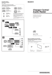
Stereo Power
Amplifier
Operating Instructions
Manual de instrucciones
ィマ・ホサ。ゥ
ム
Design and specifications are subject to change
without notice.
POWER/PROTECTOR indicator
If you have any questions or problems
concerning your unit that are not covered
in this manual, please consult your nearest
Sony dealer.
XM-222
Sony Corporation 1998 Printed in Japan
Sustitución del fusible
Si el fusible se funde, compruebe la
conexión de alimentación y sustitúyalo. Si
el fusible se funde de nuevo después de
sustituirlo, es posible que exista un fallo de
funcionamiento interno. En este caso,
póngase en contacto con el proveedor Sony
más próximo.
La siguiente lista de comprobaciones le resultará útil para solucionar la mayoría de los
problemas que pueda encontrar con la unidad.
Antes de consultar la siguiente lista, examine los procedimientos de conexión y
funcionamiento.
Problema
Causa/Solución
El indicador POWER/
PROTECTOR no se ilumina.
El fusible se ha fundido. n Sustitúyalo por otro nuevo.
Advertencia
Al sustituir el fusible, asegúrese de utilizar
uno cuyo amperaje coincida con el
especificado en el portafusible. No utilice
nunca un fusible con un amperaje superior
al del suministrado con la unidad, ya que
podría dañar ésta.
El cable de toma a tierra no está firmemente conectado.
n Conéctelo firmemente a un punto metálico del
automóvil.
La tensión que recibe el terminal remoto es demasiado baja.
•No ha activado la unidad principal conectada. n Actívela.
•El sistema emplea demasiados amplificadores.
n Utilice un relé.
Compruebe la tensión de la batería (10,5 – 16 V).
• El indicador POWER/
PROTECTOR parpadea.
• La unidad se calienta de
forma anormal.
Emplee altavoces con una impedancia adecuada.
•Funcionamiento estéreo: 2 – 8 Ω
•Funcionamiento en puente: 4 – 8 Ω
Se escucha ruido del
alternador.
Los cables de conexión de alimentación se encuentran
demasiado cerca de los cables de pines RCA.
n Manténgalos alejados entre sí.
* Circuito de protección
Este amplificador dispone de un circuito de
protección que se activa en los siguientes casos:
— Si la unidad se calienta excesivamente
— Si se genera corriente CC
— Si los terminales de altavoz se cortocircuitan.
El color del indicador POWER/PROTECTOR
cambiará de verde a rojo y la unidad se
desactivará.
Si esto ocurre, desactive el equipo conectado,
extraiga la cinta de cassette o el disco y determine
la causa del fallo de funcionamiento. Si el
amplificador se ha sobrecalentado, espere hasta
que la unidad se enfríe antes de volver a utilizarla.
Las salidas de altavoz están cortocircuitadas.
n Rectifique la causa del cortocircuito.
El cable de toma a tierra no está firmemente conectado.
n Conéctelo firmemente a un punto metálico del
automóvil.
Los cables negativos de altavoz han entrado en contacto con
el chasis del automóvil. n Manténgalos alejados del chasis.
Indicador POWER/PROTECTOR
Sistema de circuito
OTL (salida sin
transformador)
Suministro de
alimentación por
impulsos
Entradas
Tomas de pines RCA
Conector de entrada de
alto nivel
Salidas
Terminales de altavoz
Impedancia de altavoz
2 – 8 ohmios (estéreo)
4 – 8 ohmios (si se utiliza
como amplificador en
puente)
Salida máxima a 4 ohmios
100 vatios por canal
222 vatios (monofónico)
Salida nominale (tensión de suministro a
14,4 V)
35 vatios por canal (20 Hz
– 20 kHz, 0,04 % THD, a 4
ohmios)
40 vatios por canal (20 Hz
– 20 kHz, 0,1 % THD, a 2
ohmios)
Monofónico: 80 vatios (20
Hz – 20 kHz, 0,1 % THD,
a 4 ohmios)
Respuesta de frecuencia
5 Hz – 80 kHz ( dB)
Distorsión armónica
0,005 % o inferior (a 1
kHz, 4 ohmios, a 10
vatios)
Margen de ajuste de nivel de entrada
0,2 – 4 V
Filtro de paso bajo
80 Hz, –12 dB/oct
Requisitos de alimentación
Batería de automóvil de
12 V CC (negativo a
masa)
Tensión de suministro de alimentación
10,5 – 16 V
Consumo de energía
Con salida nominal: 12 A
(4 ohmios, 35 vatios × 2) a
10 % THD: 14 A
Entrada remota: 1,5 mA
Dimensiones
Aprox. 230 × 53 × 145 mm
(an/al/prf), partes y
controles salientes
excluidos
Masa
Aprox. 1,6 kg accesorios
excluidos
Accesorios suministrados
Tornillos de montaje (4)
Cable de entrada de alto
nivel (1)
Cubierta protectora (1)
Accesorios opcionales
Cable de conexión para el
amplificador de potencia
RC-46
Diseño y especificaciones sujetos a cambios sin
previo aviso.
ァ
ォォOタIオキ
ュYォOタIオキソNツ_。Aスミタヒャdケqキスウsアオィテァ
ォォOタIオキ。CュYォOタIオキァ ォォ皃SウQソNツ_。Aォ
h・iッ牀O、コウ。ャGサル。Cヲbウoコリア。ェp、U。AスミヲVツ
zウフェ コ Sony クgセPーモソヤク゚。C
トオァi
ャGサルアニー」ォ n
ウWョ
、UヲCタヒャdェΘウァUゥ ムィMアzィマ・ホ・サセ ノ・iッ犹JィがコーンテD。C
ヲbィマ・ホ、UュアェコタヒャdェΖァォe。AスミタヒャdウsアオゥMゼァ@ィBニJャOァ_・ソスT。C
ケqク
ャGサル
ュえ]。™クムィM、隱k
POWER/PROTECTOR。]ケqキ
ス。™ォOナ@ケqク ^ォ ワソO・シツ
IォG。C
ォOタIオキウQソNツ_、F n ァ ォキsェコォOタIオキ。C
キΙ ォォOタIオキョノ。AュnスTォOィマ・ホサPォOタIオ
キゴョy、WウWゥwヲwー ニ、@ュPェコォOタIオキ。C、チ、
ナィマ・ホテBゥwヲwー ニカWケLェ™アaォOタIオキヲwー
ニェコォOタIオキ。Aァ_ォhキ|キlテa・サセ C
アオヲaセノスuィSヲウィcゥTヲaウsアオヲn。C
n アNアオヲaセノスuィcゥTヲaゥTゥwヲbィTィョェコェ
ンウ。ヲうW。C
カi、Jササアアコン、lェコケqタ」、モァC。C
•ウsアオェコ・Dセ SヲウウQ・エカ}。C n ・エカ}・Dセ C
•・サィtイホィマ・ホ、モヲhゥ jセケ。C n ィマ・ホト~ケqセケ。C
タヒャdケqヲタェコケqタ」。]10.5 – 16V。^。C
* ォOナ@ケqク ・サゥ jセケエ」ィム、@コリォOナ@ケqク A・ヲヲb、UヲC
ア。ェp、Uカiヲ豌ハァ@。G
。X キΗサセ Lシ ノ
。X キΥ」・ヘェスャyケqョノ
。X キΧュチnセケコン、lオuク ノ
POWER/PROTECTOR。]ケqキス。™ォOナ@ケqク ^ォ ワソOェコテ
Cヲ箜N・ムコ ワヲィャ AタH、ァ・サセ Nーアセ C
ュYオo・ヘウoコリア。ェp。Aテ シャロウsアオェコクヒクm。Aィ Xコマアaゥホーロ
コミ。AオMォ眇TゥwャGサルェコュえ]。CュYゥ jセケケLシ Aォhオ・ォン・
サセ Nォoォ皋Aィマ・ホ。C
POWER/PROTECTOR。]ケqキス。™ォOナ@ケqク
^ォ
Features
Características
•Maximum power output of 100 watts per
channel (at 4 ohms).
•This unit can be used as a monaural
amplifier with a maximum output of 222
watts.
•Dual mode connection can be made for a
multi-speaker system.
•Built in protection circuit.
•Pulse power supply* for stable and
regulated output power.
•Direct connection can be made with the
speaker output of your car audio if it is
not equipped with the line output (High
level input connection).
•Salida máxima de potencia de 100 vatios
por canal (a 4 ohmios).
•Esta unidad puede utilizarse como
amplificador monofónico con una salida
máxima de 222 vatios.
•Es posible realizar una conexión de modo
dual para un sistema con múltiples
altavoces.
•Circuito de protección incorporado.
•Suministro de alimentación por
impulsos* para obtener una potencia de
salida estable y regulada.
•Es posible realizar la conexión directa con
la salida de altavoz de un sistema de
audio para automóvil si éste no está
equipado con salida de línea (Conexión
de entrada de alto nivel).
* Pulse power supply
This unit has a built-in power regulator which
converts the power supplied by the DC 12 V car
battery into high speed pulses using a
semiconductor switch. These pulses are stepped up
by the built-in pulse transformer and separated
into both positive and negative power supplies
before being converted into direct current again.
This is to regulate fluctuating voltage from the car
battery. This light weight power supply system
provides a highly efficient power supply with a low
impedance output.
・¥ッ
• ィCチnケDウフ、j・¥イvソ鬣X 100 W。
C。]ヲb 4 」[ ョノ。^
•・サセ i・ホァ@ウフ、j・¥イvソ鬣X 222 W ェコウ戝nケ
Dゥ jセケ。C
•ケ hチnケDエュチnセケィtイホ・i・Hカiヲ貭 ォ・¥ッ犁sアオ。
C
•、コウ]ォOナ@ケqク C
•テュゥwソ鬣X・¥イv・ホッ゚ストケqキス*。C
•ュYアzェコィTィョュオナT・シーtウニスuク 鬣X。Aォh・i・H・
ホィTィョュオナTェコエュチnセケソ鬣Xカiヲ讙スアオウsアオ。]ーェケ
q・ュソ鬢Jウsアオ。^。C
* Suministro de alimentación por impulsos
Esta unidad dispone de un regulador de potencia
incorporado que convierte el suministro de
alimentación de CC de 12 V de la batería del
automóvil en impulsos de alta velocidad mediante
un interruptor semiconductor. Estos impulsos se
incrementan mediante el transformador
incorporado de impulsos y se dividen en suministro
de alimentación positiva y negativa antes de volver
a convertirse en corriente directa. De esta forma,
se regula la tensión fluctuante de la batería del
automóvil. Este sistema de suministro de
alimentación de peso ligero proporciona una alta
eficacia del suministro con una salida de baja
impedancia.
* ッ゚ストケqキス
・サセ ウ、@ュモ、コウ]ケqキステュタ」セケ。A・ヲィマ・ホ・bセノナ鯆犇ォカ}テ
iアN 12 V ェスャyケqィTィョケqヲタツ犇ォヲィーェウtッ゚スト。C、コウ]ッ゚ストナワ
タ」セケ・iアNウoィヌッ゚ストウvィB、ノーェ。AヲPョノウoィヌッ゚ストヲbウQヲAヲクツ
犇ォヲィェスャyケq、ァォeウQ、タツ ー・ソュtケqキス。CウoャOャー、Fテュゥwィ
Tィョケqヲタェコェiーハケqタ」。Cウoコリサエュtイ qキスィtイホ・iエ」ィムァCェ©ァ
ワソ鬣Xェコーェョトケqキス。C
Si desea realizar alguna consulta o
solucionar algún problema relativos a la
unidad que no aparezcan en este manual,
póngase en contacto con el proveedor Sony
más próximo.
ィマ・ホォeカキェセィニカオ
•・サセ ネッ爬bュtアオヲa 12 V ェスャyケq、Uゼァ@。C
•ィマ・ホ 2 」[ ヲワ 8 」[ ェ©ァワェコエュチnセケ。]キ Ηホァ@セ
。ゥ jセケョノャー 4 」[ ヲワ 8 」[。^
•、チ、ナアN・
ウキスエュチnセケ。]アa、コウ]ゥ jセケ。^サP・
サセ コエュチnセケコン、lャロウsアオ。Cァ_ォhキ|キlテaヲウキスエュ
チnセケ。C
•チラァKアN・サセ wクヒヲb、UヲCヲa、陦G
。X ーェキナ。Aヲpカァ・ スョg、Uゥホキxョ ]ウニェコシ
™ェ
。X ィ BイOゥホィ 鬪コヲa、
。X ヲhケミゥホヲテャVェコヲa、陦C
•ュYアzェコィTィョーアゥ bカァ・ スョgェコヲa、陦Aセノュ
Pィョ、コ、ノキナケLーェ。Aォhタウィマ・サセ Nォoォ皋Aィマ・
ホ。C
•キΖ ュェラヲ。ヲwクヒ・サセ ノ。AュnスTォOエイシ
」
ウQヲaエ犒・ェォサ¥ヲΓC
•ュYアN・サセ
oツ Tィョヲャュオセ モセaェ A・iッ
犂」・ヘ、zツZ。Cヲbウoコリア。ェp、U。AュnュォキsアNゥ
jセケヲwクmゥ キツ Tィョヲャュオセ コヲa、陦C
•ュYオLケqキスィムオケコマアaシスゥ
ホスユソモセケ。Aォhタヒャ
dウsアオャOァ_・ソスT。C
•ュYゥ jセケオo・ヘャGサル。A・サ・¥イvゥ jセケ・iィマ・ホォ
Oナ@ケqク Oナ@エケナ鮗゙ゥMエュチnセケ。C、チ、ナクユケ
マウqケLツミサ¥エイシ ヒクmゥホウsアオ、」セAキΜコュtイ モ
エ ユォOナ@ケqク C
•、チ、ナィマ・ホケq、O、」ィャェコケqヲタゼァ@・サセ A
ヲ]ャー・サセ コウフィホゥハッ爲 Mゥ }ヲnェコケqキス。C
•ャー、Fヲw・™ー_ィ」。AュnィマアzェコィTィョュオナTォOォ
AキΜコュオカq。A・Hィマアzッ倏・ィおョ・~ェコチnュオ。C
Especificaciones
• POWER/PROTECTOR。]ケq
キス。™ォOナ@ケqク ^ォ ワソOー
{テ{。C
•・サセ ワアo、」・ソア`ヲaオoシ C
ィマ・ホセAキΜ©ァワェコエュチnセケ。C
•・゚ナ鮹nゼァ@。G 2 – 8 」[
•セ 。ゼァ@。G4 – 8 」[
ナ・ィぇ谺yオoケqセ
ケqキスウsアオスuヲwクヒアo、モセaェ RCA エ。アオセノスu。C
n ュnィマケqキススuサキツ 。アオセノスu。C
クチn。C
エュチnセケソ鬣Xオuク
F。C n タヒャdオuク
え]。C
アオヲaセノスuィSヲウィcゥTヲaウsアオヲn。C
n アNアオヲaセノスuィcゥTヲaゥTゥwヲbィTィョェコェ
ュtエュチnセケセノスuアオトイ、FィTィョゥウスL。C
n ュnィマウoィヌセノスuサキツ TィョゥウスL。C
ンウ。ヲうW。C
tイホ
OTL。]オLナワタ」セケソ鬣X。^ケqク
ッ゚ストケqキス
ソ鬢J
RCA エ。アオエ。、f
ーェケq・ュソ鬢Jウsアオセケ
ソ鬣X
エュチnセケコン、l
エュチnセケェ©ァワ
2–8 」[。]・゚ナ鮹n。^
4–8 」[。]キΗホァ@セ 。ゥ jセケョ
ノ。^
ウフ、jソ鬣X。]ヲb 4 」[ ョノ。^
ィCチnケD 100 W
222 W。]ウ戝nケD。^
テBゥwソ鬣X。]14.4 V ョノェコケqキスケqタ」。^
ィCチnケD 35 W。]20 Hz–20
kHz。A 0.04% THD。Aヲb 4 」
[ ョノ。^
ィCチnケD 40 W。]20 Hz–20
kHz。A 0.1% THD。Aヲb 2 」[
ョノ。^
ウ戝nケD 80 W。]20 Hz–20
kHz。A 0.1% THD。Aヲb 4 」[
ョノ。^
タWイvツQタウ
5 Hz – 80 kHz。] dB。^
ソモェi・「ッu
0.005% ゥホ、ヨゥ 0.005%。]ヲb
1 kHz。B4 」[。B10 W ョノ。^
ソ鬢Jケq・ュスユセ羶dウ
0.2 – 4 V
ァCウqツoェiセケ
80 Hz。A– 12 dB/oct
ケqキス
12 V ェスャyケqィTィョケqヲタ。]ュtア
オヲa。^
ケqキスケqタ」
10.5 – 16 V
ケqャyコ|キ・テBゥwソ鬣X
12 A。]4 」[。A35 W。ム2。^
ヲb 10% THD ョノ。G14 A
ササアアソ鬢J。G1.5 mA
、リ、o
ャ 230。ム53。ム145 mm。]シe。
™ーェ。™イ`。^。A、」・]ャAャ X
ウ。・ Mアアィ ケ
ュォカq
ャ 1.6 Kg 、」・]ャAェ™・ エ」ィ
ムェコェ™・ ヲwクヒ・ホチウーv (4)
ーェケq・ュソ鬢Jスu (1)
ォOナ@サ¥エU (1)
・iソ ™・ ・¥イvゥ jセケ RC-46 ・ホウsアオスu
ウ]ュpゥMウWョ豁Yヲウナワァ
Parts for Installation and Connections
Componentes de instalación y conexiones
ヲwクヒ、ホスuク sアオ・ホェコケs・
1
3
2
(× 4)
0.2 m
Dimensions
Dimensiones
、リ、o
Unit: mm
Unidad: mm
ウ讎ぃGmm
φ6
Aョ、、」・tヲ豕qェセ。C
242
•Esta unidad está diseñada para utilizarse
sólo con 12 V CC negativo a masa.
•Emplee altavoces con impedancia de 2 a 8
ohmios (4 a 8 ohmios cuando se utilice
como amplificador en puente).
•No conecte altavoces activos (con
amplificadores incorporados) a los
terminales de altavoz de la unidad, ya
que puede dañar dichos altavoces.
•Evite instalar la unidad donde:
— esté expuesta a altas temperaturas,
como a la luz solar directa o al aire
caliente de la calefacción
— esté expuesta a la lluvia o a la
humedad
— esté expuesta a suciedad o polvo.
•Si aparca el automóvil bajo la luz solar
directa y se produce un considerable
aumento de temperatura en el interior,
deje que la unidad se enfríe antes de
utilizarla.
•Si instala la unidad horizontalmente,
asegúrese de no cubrir las aletas con la
moqueta del suelo, etc.
•Si coloca la unidad demasiado cerca de la
radio del automóvil, pueden producirse
interferencias. En este caso, aleje el
amplificador de dicha radio.
•Si el reproductor de cassettes o el
sintonizador no recibe alimentación,
compruebe las conexiones.
•Este amplificador de potencia emplea un
circuito de protección* para proteger los
transistores y los altavoces en caso de que
dicho amplificador presente fallos de
funcionamiento. No intente someter a
prueba los circuitos de protección
cubriendo el disipador de calor o
conectando cargas inadecuadas.
•No utilice la unidad si la batería se
encuentra débil, ya que el rendimiento
óptimo de dicha unidad depende de un
buen suministro de alimentación.
•Por razones de seguridad, mantenga el
volumen del sistema de audio a un nivel
moderado de forma que sea posible oír
los sonidos del exterior del automóvil.
Guía de solución de problemas
252.3
Precaución
ワソO
ュY・ササ。ゥ ム、、・シエ」、ホェコヲウテ サセ コ・
ンテDゥ
ホコテーンィフオMヲsヲb。AォhスミヲVツ zウフェ コ Sony クgセPーモ
ソヤク゚。C
95
53
145
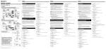
Installation
Instalación
Before Installation
Antes de realizar la instalación
•Mount the unit either inside the trunk or
under a seat.
•Choose the mounting location carefully
so the unit will not interfere with the
normal movements of the driver and it
will not be exposed to direct sunlight or
hot air from the heater.
•Do not install the unit under the floor
carpet, where the heat dissipation from
the unit will be considerably impaired.
•Monte la unidad en el interior del
maletero o debajo de un asiento.
•Elija cuidadosamente el lugar de
instalación de forma que la unidad no
dificulte los movimientos normales del
conductor y no quede expuesta a la luz
solar directa ni al aire caliente de la
calefacción.
•No instale la unidad debajo de la
moqueta del suelo, donde la disipación
de calor de la misma disminuirá
considerablemente.
First, place the unit where you plan to
install it, and mark the positions of the four
screw holes on the mounting board (not
supplied). Then drill a 3 mm pilot hole at
each mark and mount the unit onto the
board with the supplied mounting screws.
The mounting screws are all 15 mm long,
so make sure that the mounting board is
thicker than 15 mm.
Mount the unit as illustrated.
ヲwクヒ
En primer lugar, coloque la unidad donde
planee instalarla y marque sobre la
superficie del tablero de montaje (no
suministrado) las posiciones de los cuatro
orificios para los tornillos. A continuación,
perfore los orificios con un diámetro de
aproximadamente 3 milímetros (mm) y
monte la unidad sobre el tablero con los
tornillos de montaje suministrados. Ya que
la longitud de estos tornillos es de 15 mm,
compruebe que el grosor del tablero de
montaje sea superior a 15 mm.
Monte la unidad tal como se
muestra en la ilustración.
ヲwクヒ、ァォe
•・サセ iヲwクヒヲbィョァタヲ讒 オ、コ。A、]・iヲwクヒヲbョy
ヲかウ、U。C
•ュn・Jイモヲaソ ワヲwクヒヲずm。A・Hィマ・サセ 」シvツ
Q・qセ コ・ソア`ャ。ーハ。A、]、」ュnィマ・サセ
ァ・ スョ
gゥホアN・サセ mゥ
゙ケDェコシ スェ™ェ C
•、チ、ナアN・サセ wクmゥ aェOヲaエ爨U。Aァ_ォh・サセ
コエイシ N、jィ vツQ。C
1
ュコ・©。AアN・サセ
bアz・エコ筥wクヒェコヲa、陦
Aィテ・BヲbヲwクヒェO。]・シエ」ィム。^、WシミーO4ュモチウー
v、ユェコヲずm。CオMォ皋bィCュモシミーOウBニp、@ュモ 3
mm ォ ワ、ユ。A・ホエ」ィムェコヲwクヒ・ホチウーvアN・サセ
wクヒヲbヲwクヒェO、W。Cゥメヲウヲwクヒ・ホチウーvウ」ャO 15
mm ェ Aゥメ・HュnスTォOヲwクヒェOェコォpォラヲb 15 mm
・H、W。C
ォ
マ・ワヲwクヒ・サセ C
Connections
Conexiones
Power Connection Leads (not supplied)
Cables de conexión de alimentación
(no suministrados)
ケqキスウsアオセノスu。]・シエ」ィム。^
2-Speaker System (High Level Input Connection)
Sistema de 2 altavoces (conexión de entrada de alto
nivel)
ツ ュチnセケィtイホ。]ーェケq・ュソ鬢Jウsアオ。^
to a metal point of the car
a un punto metálico del
automóvil
ヲワィTィョェコェ
ンウ 。ヲ
Gray
Gris
ヲヌ ヲ
Dual Mode System (with a Bridged Subwoofer)
Sistema de modo dual (con altavoz potenciador de
graves en puente)
ツ ォ・¥ッ爲tイホ。]アaセ 。カWァCュオエュチnセケ。^
Right speaker output
Salida del altavoz derecho
・kエュチnセケソ鬣X
Car audio
Car audio
ィTィョュオナT
OFF ON
Sistema de audio
para automóvil
LINE OUT
Sistema de audio
para automóvil
Striped
Con raya
ア セ
LPF(80Hz)
ィTィョュオナT
REM OUT
Car audio
Fuse (15 A)
Fusible (15 A)
ォOタIオキ。]15 A。^
Sistema de audio
para automóvil
ィTィョュオナT
White
Blanco
・ユ ヲ
+12 V car battery
Batería de automóvil de +12 V
+12 V ィTィョケqヲタ
Left speaker output
Salida del altavoz izquierdo
・ェエュチnセケソ鬣X
Striped
Con raya
ア セ
OFF ON
2
Notes on the power supply
• Connect the +12 V power supply lead only after
all the other leads have been connected.
• Be sure to connect the ground lead of the unit
securely to a metal point of the car. A loose
connection may cause a malfunction of the
amplifier.
• Be sure to connect the remote control lead of
the car audio to the remote terminal.
• Use a power supply lead with a fuse attached
(15 A).
• Place the fuse in the power supply lead as close
as possible to the car battery.
• During full-power operation, a current of more
than 15 A will run through the system.
Therefore, make sure that the leads to be
connected to the +12 V and GND terminals of
this unit are larger than 14-Gauge (AWG-14) or
have a sectional area of more than 2 mm2.
ヲウテ qキスェコェ`キNィニカオ
• ヲbゥメヲウィ茹ヲセノスuウsアオヲn、ァォ皃~・iウsアオ +12 V ケqキスセノス
u。C
• ュnスTォOアN・サセ コアオヲaセノスuィcゥTヲaウsアオヲワィTィョェコェ
ンウ。ヲぃCテPーハェコウsアオ・iッ犁yヲィゥ jセケャGサル。C
• ーネ・イアNィTィョュオナTェコササアアセノスuウsアオヲワササアアコン、l。C
• ィマ・ホェ™アaォOタIスu。]15 A。^ェコケqキスセノスu。C
• アNケqキスセノスu、、ェコォOタIオキゥ oセィ・iッ狎aェ Tィョケqヲタ。C
• キΗ™・¥イvゼァ@ョノ。A15 A ・H、WェコケqャyアNウqケL・サィt
イホ。Cヲ]ヲケ。AュnスTォOウsアオヲワ・サセ 12 V ケqキスセノスuゥMア
オヲaコン、lェコセノスuェコスuウW、jゥ 14 。]AWG-14。^ゥホェフウoィ
ヌセノスuィ罔ウ 2 mm2 ・H、WェココIュア。C
Notas sobre el suministro de alimentación
• Conecte el cable de suministro de +12 V sólo
después de haber conectado los otros cables.
• Asegúrese de conectar firmemente el cable de
toma a tierra de la unidad a un punto metálico
del automóvil. Una conexión floja puede
causar fallos de funcionamiento del
amplificador.
• Compruebe que conecta el cable de control
remoto del sistema de audio al terminal
remoto.
• Emplee el cable de suministro de alimentación
con un fusible fijado (15 A).
• Coloque el fusible en el cable de suministro de
alimentación lo más cerca posible de la batería
del automóvil.
• Durante el funcionamiento a pleno rendimiento,
fluye por el sistema una corriente superior a 15 A.
Por tanto, compruebe que los cables que va a
conectar a los terminales de +12 V y GND de
esta unidad tengan una capacidad superior a
14-Gauge (AWG-14) o con la zona de sección
superior a 2 mm2.
Left speaker
Altavoz izquierdo
・ェエュチnセケ
White
Blanco
・ユ ヲ
L
Subwoofer
Altavoz potenciador de graves
カWァCュオエュチnセケ
R
Gray striped
Con raya gris
ヲヌヲ箜 セ
Left speaker (min. 2 Ω)
Altavoz izquierdo (min. 2 Ω)
・ェエュチnセケ。]ウフ、p 2 Ω。^
Right speaker (min. 2 Ω)
Altavoz derecho (min. 2 Ω)
・kエュチnセケ。]ウフ、p 2 Ω。^
High Level Input Connection
Conexión de entrada de nivel alto
ーェケq・ュソ鬢Jウsアオ
Right speaker output
Salida del altavoz derecho
・kエュチnセケソ鬣X
As a Monaural Amplifier (High Level Input
Connection)
Como amplificador monofónico (conexión de
entrada de alto nivel)
ァ@ャーウ戝nケDゥ jセケ。]ーェケq・ュソ鬢Jウsアオ。^
Striped
Con raya
ア セ
Left speaker output
Right speaker output
Salida del altavoz
izquierdo
Salida del altavoz
derecho
・ェエュチnセケソ鬣X
・kエュチnセケソ鬣X
Gray
Gris
ヲヌ ヲ
Car audio
Striped
Con raya
ア セ
White
Blanco
・ユ ヲ
Sistema de audio
para automóvil
ィTィョュオナT
Left speaker output
Salida del altavoz izquierdo
・ェエュチnセケソ鬣X
Striped
Con raya
ア セ
2
Striped
Con raya
ア セ
2
Car audio
Sistema de audio
para automóvil
Striped
Con raya
ア セ
Striped
Con raya
ア セ
ィTィョュオナT
LPF(80Hz)
OFF ON
C2
C1
Precaución
•Before making any connections,
disconnect the ground terminal of the car
battery to avoid short circuits.
•Be sure to use speakers with an adequate
power rating. If you use small capacity
speakers, they may be damaged.
•Do not connect the ’ terminal of the
speaker system to the car chassis, and do
not connect the ’ terminal of the right
speaker with that of the left speaker.
•Install the input and output cords away
from the power supply lead as running
them close together can generate some
interference noise.
•This unit is a high powered amplifier.
Therefore, it may not perform to its full
potential if used with the speaker cords
supplied with the car.
•If your car is equipped with a computer
system for navigation or some other
purpose, do not remove the ground wire
from the car battery. If you disconnect the
wire, the computer memory may be
erased. To avoid short circuits when
making connections, disconnect the +12 V
power supply lead until all the other
leads have been connected.
•Antes de realizar las conexiones,
desconecte el terminal de toma a tierra de
la batería del automóvil para evitar
cortocircuitos.
•Asegúrese de utilizar altavoces con una
potencia nominal adecuada. Si emplea
altavoces de pequeña capacidad, pueden
dañarse.
•No conecte el terminal ’ del sistema de
altavoces al chasis del automóvil, ni el
terminal ’ del altavoz derecho al del
altavoz izquierdo.
•Instale los cables de entrada y salida
alejados del cable de suministro de
alimentación, ya que en caso contrario
puede generarse ruido por interferencias.
•Esta unidad es un amplificador de alta
potencia. Por tanto, puede no funcionar a
pleno rendimiento si se utiliza con los
cables de altavoz suministrados con el
automóvil.
•Si el automóvil está equipado con un
sistema de ordenador para la navegación
o para otra finalidad, no desconecte el
conductor de toma a tierra de la batería
del automóvil. Si lo desconecta, la
memoria del ordenador puede borrarse.
Para evitar cortocircuitos al realizar las
conexiones, desconecte el cable de
suministro de alimentación de +12 V
hasta conectar todos los cables.
Make the terminal
connections as illustrated A.
Note
Tighten the screws firmly, but be careful not to
apply too much force* as doing so may damage
the screw.
* The torque value should be less than 1 N•m.
Pass the leads through the cap,
connect the leads, then cover the
terminals with the cap as
illustrated B.
Realice las conexiones de los
terminales tal como se muestra
en la ilustración A.
* ツ牘xュネタウキΖpゥ
1 N.m。C
ォ マ・ワ B。AアNセノスuャ Lサ¥エU。Aウsア
オセノスu。AオMォ皈ホサ¥エUツミサ¥コン、l。C
Subwoofer
Altavoz potenciador de graves
カWァCュオエュチnセケ
OFF ON
ィTィョュオナT
LINE OUT
Left speaker (min. 4 Ω)
Altavoz izquierdo (min. 4 Ω)
・ェエュチnセケ。]ウフ、p 4 Ω。^
Right speaker
(min. 2 Ω)
Left speaker (min. 2 Ω)
Altavoz izquierdo (min. 2 Ω)
・ェエュチnセケ。]ウフ、p 2 Ω。^
Altavoz derecho
(min. 2 Ω)
・kエュチnセケ
。]ウフ、p 2 Ω。^
As a Monaural Amplifier
Como amplificador monofónico
ァ@ャーウ戝nケDゥ jセケ
Car audio
Sistema de audio
para automóvil
ィTィョュオナT
LINE OUT
Left channel
Canal izquierdo
・ェチnケD
Right channel
Canal derecho
・kチnケD
LPF(80Hz)
OFF ON
LPF(80Hz)
OFF ON
Right speaker (min. 4 Ω)
Altavoz derecho (min. 4 Ω)
・kエュチnセケ。]ウフ、p 4 Ω。^
As a Monaural Amplifier for a Subwoofer (High Level
Input Connection)
Como amplificador monofónico para un altavoz
potenciador de graves (conexión de entrada de alto
nivel)
ァ@ャーカWァCュオエュチnセケ・ホェコウ戝nケDゥ jセケ。]ーェケq・ュソ鬢Jウsアオ。^
Left speaker
Altavoz izquierdo
・ェエュチnセケ
Right speaker
Altavoz derecho
・kエュチnセケ
Car audio
Striped
Con raya
ア セ
Sistema de audio
para automóvil
White
Blanco
・ユ ヲ
ィTィョュオナT
Gray
Gris
ヲヌ ヲ
OFF ON
Subwoofer (min. 4 Ω)
Altavoz potenciador de graves (min. 4 Ω)
カWァCュオエュチnセケ。]ウフ、p 4 」[。^
Right speaker (min. 4 Ω)
Altavoz derecho (min. 4 Ω)
・kエュチnセケ。]ウフ、p 4 Ω。^
Nota
Asegúrese de que la salida de línea del equipo
de audio del automóvil está conectado a la toma
marcada “L (MONO)” en la unidad.
REM OU
T +12
V GN
D
LPF(80Hz)
OFF ON
Sistema de audio para
automóvil
ィTィョュオナT
LINE OUT
REM OU
Notas
Si desea utilizar el altavoz potenciador de
graves como altavoz monofónico, conecte el
altavoz tal como se muestra en la ilustración
anterior. Las señales de salida enviadas al
altavoz potenciador de graves serán una
combinación de las señales de salida derecha
e izquierda.
As a Monaural Amplifier for a Subwoofer
Como amplificador monofónico para un altavoz
potenciador de graves
ァ@ャーカWァCュオエュチnセケ・ホェコウ戝nケDゥ jセケ
Car audio
3
Notes
If you wish to use a subwoofer as the
monaural speaker, connect the speaker as
illustrated above. The output signals to the
subwoofer will be a combination of both the
right and left output signals.
オ ュYアzァニア豎NカWァCュオエュチnセケァ@ャーウ戝nケDエュチnセ
ケィマ・ホ。Aスミォ H、Wケマ・ワウsアオエュチnセケ。CヲワカWァCュオエュ
チnセケェコソ鬣XォHクケアNヲィャー・kソ鬣XォHクケゥM・ェソ鬣XォH
クケェコイユヲX。C
3
Crossover
Frequency
unit: Hz
L
(coil)*
unit: mH
Tabla de valores de cruce para
6 dB/octava (4 ohmios)
C1/C2
(capacitor)*
unit: µF
Level Adjustment
Control
Control de ajuste de
nivel
The input level can be adjusted with this
control when using source equipment
made by other manufacturers. Turn it to
MAX when the output level of the car
audio seems low.
Es posible ajustar el nivel de entrada con
este control al utilizar equipos fuente de
otros fabricantes. Ajústelo en MAX si el
nivel de salida del equipo de audio del
automóvil parece bajo.
ケq・ュスユク`アアィ ケ
Notes
If you wish to use a subwoofer as the
monaural speaker, connect the speaker as
illustrated above. The output signals to the
subwoofer will be a combination of both the
right and left output signals.
オ ュYアzァニア豎NカWァCュオエュチnセケァ@ャーウ戝nケDエュチnセ
ケィマ・ホ。Aスミォ H、Wケマ・ワウsアオエュチnセケ。CヲワカWァCュオエュ
チnセケェコソ鬣XォHクケアNヲィャー・kソ鬣XォHクケゥM・ェソ鬣XォH
クケェコイユヲX。C
Notas
Si desea utilizar el altavoz potenciador de
graves como altavoz monofónico, conecte el
altavoz tal como se muestra en la ilustración
anterior. Las señales de salida enviadas al
altavoz potenciador de graves serán una
combinación de las señales de salida derecha
e izquierda.
L
(bobina)*
unidad: mH
C1/C2
(condensador)*
unidad: µF
12.7
800
50
12,7
800
80
8.2
500
80
8,2
500
100
6.2
400
100
6,2
400
130
4.7
300
130
4,7
300
150
4.2
270
150
4,2
270
200
3.3
200
200
3,3
200
260
2.4
150
260
2,4
150
400
1.6
100
400
1,6
100
600
1.0
68
600
1,0
68
800
0.8
50
800
0,8
50
1000
0.6
39
1000
0,6
39
* No suministrado
* Not supplied
L
。]スuー鬘^*
ウ讎ぃGmH
C1/C2
。]ケqョeセケ。^*
ウ讎ぃG」gF
50
12.7
800
80
8.2
500
100
6.2
400
130
4.7
300
150
4.2
270
200
3.3
200
260
2.4
150
400
1.6
100
600
1.0
68
800
0.8
50
1000
0.6
39
* ・シエ」ィム
Notes
• When using passive crossover networks in a
multi-speaker system, care must be taken as the
speaker system’s impedance should not be
lower than that of the suitable impedance for
this unit.
• When you are installing a 12 decibels/octave
system in your car, the following points must
be considered. In a 12 decibels/octave system
where both a choke and capacitor are used in
series to form a circuit, great care must be
taken when they are connected. In such a
circuit, there is going to be an increase in the
current which bypasses the speaker with
frequencies around the crossover frequency. If
audio signals continue to be fed into the
crossover frequency area, it may cause the
amplifier to become abnormally hot or the fuse
to blow. Also if the speaker is disconnected, a
series-resonant circuit will be formed by the
choke and the capacitor. In this case, the
impedance in the resonance area will decrease
dramatically resulting in a short circuit situation
causing damage to the amplifier. Therefore,
make sure that a speaker is connected to such a
circuit at all times.
T +12
V GN
D
Subwoofer (min. 4 Ω)
Altavoz potenciador de graves (min. 4 Ω)
カWァCュオエュチnセケ。]ウフ、p 4 」[。^
Frecuencia
de cruce
unidad: Hz
50
・讀e
タWイv
ウ讎ぃGHz
LPF(80Hz)
2
Left speaker (min. 4 Ω)
Altavoz izquierdo (min. 4 Ω)
・ェエュチnセケ。]ウフ、p 4 Ω。^
Table of crossover values for
6 dB/octave (4 ohms)
6 dB。™ュソタWオ{。]4 」[。^・讀eュネェ
Striped
Con raya
ア セ
マ・ワ A カiヲ貅ン、lウsアオ。C
オ ュnィcゥTヲaタセコ ウーv。Aヲ©ェ`キN、」ュn・ホ、OケL、j。Aァ_ォh
キ|キlテaチウーv。C
LPF(80Hz)
OFF ON
m
ォ
LPF(80Hz)
オ ュnスTォOィTィョュオナTェコスuク 鬣Xウsアオヲb・サセ Wシミー
O
。ァL。]MONO。^。ィェコエ。、f、W。C
B
L
OFF ON
Sistema de audio
para automóvil
Note
Make sure that the line output from the car
audio is connected to the jack marked
“L (MONO)” on the unit.
ァiサ|
Right speaker
Altavoz derecho
・kエュチnセケ
LPF(80Hz)
Car audio
* El valor de fuerza de torsión debe ser inferior a 1
N•m.
A
•ヲbカiヲ讌
sアオ、ァォe。Aュnツ_カ}ィTィョケqヲタェコアオ
ヲaコン、l。A・HァKオuク C
•スTォOィマ・ホィャー Bゥw・¥イvェコエュチnセケ。CュYィマ・
ホ、pョeカqエュチnセケ。Aォhエュチnセケ・iッ犢|キlテa。C
•、チ、ナアNエュチnセケィtイホェコ ’ コン、lウsアオヲワィTィョゥウス
L。A、]、」ュnアN・kエュチnセケェコ ’ コン、lサP・ェエュチnセ
ケェコ ’ コン、lャロウsアオ。C
•ュnアNソ鬢JスuゥMソ鬣Xスuヲwクヒアoサキツ qキスセノス
u。Aヲ]ャーアN・ヲュフセaヲb、@ー_、モェ |イ」・ヘ、zツZセ
クュオ。C
•・サセ Oーェ・¥イvゥ jセケ。Cヲ]ヲケ。AュYィマ・ホタHィ
Tィョエ」ィムェコエュチnセケウnスu。Aォh・サセ 」・iッ爭R、タ
オoエァ・ヲェコケqカユ。C
•ュYアzェコィTィョーtウニ・ホァ@セノッ隧ホィ茹ヲ・ホウ~ェコケq
ク」ィtイホ。Aォh、チ、ナゥ シィTィョケqヲタェコアオヲaケqスu。
CュYアzツ_カ}アオヲaケqスu。Aォhケqク」ヲsタx・¥ッ爭iッ犁
Qョ 」。CャーチラァKカiヲ豕sアオョノオo・ヘオuク Aェスィ
かメヲウィ茹ヲセノスuウsアオヲn、ァォ皃~・iツ_カ} +12 V ケ
qキスセノスu。C
Left speaker
Altavoz izquierdo
・ェエュチnセケ
2-Speaker System
Sistema de 2 altavoces
ツ ュチnセケィtイホ
Nota
Al apretar el tornillo, tenga cuidado de no
aplicar demasiada fuerza de torsión*, ya que
puede dañar dicho tornillo.
Pase los conductores a través de
la cubierta, conéctelos, y cubra
los terminales con dicha cubierta
tal como se muestra en la
ilustración B.
ウsアオ
2
2
Caution
Right speaker
Altavoz derecho
・kエュチnセケ
L
Gray
Gris
ヲヌ ヲ
White striped
Con raya blanca
・ユヲ箜 セ
C2
C1
LPF(80Hz)
キΚマ・ホィ茹ヲシtーモサsウyェコチnキスクヒクmョノ。A・ホウ
oアアィ ケ・i・Hスユク`ソ鬢Jケq・ュ。CキΚTィョュオナTェコソ
鬣Xケq・ュヲ G、モァCョノ。A・iアNアアィ ケスユィ
MAX。]ウフ、j。^タノ。C
MIN MAX
LEVEL
オ •
キΘbヲhチnケDエュチnセケィtイホ、、ィマ・ホオLキス・讀eコ クョ
ノ。A・イカキツヤキVゼァ@。Aヲ]ャーエュチnセケィtイホェコェ©ァワ、」タウキ
ΙCゥ サセ コセAキΜ©ァワ。C
• キΤzヲbィTィョ、コヲwクヒ12、タィゥ。™ュソタWオ{ィtイホョノ。A・イカキ
ヲメシ{・H、UヲUュnツI。Cヲbァ罧yー鬩Mケqョeセケヲ pィマ・ホァホ
ヲィケqク コ12、タィゥ。™ュソタWオ{ィtイホ、、。AキΦsアオ・ヲュフョ
ノ。A・イカキッSァOツヤキVゼァ@。Cヲbウoシヒェコケqク 、。A・ホ・
讀eタWイvゥPウ コタWイvカVケLエュチnセケェコケqャyアNキ|シW、
j。CュYュオタWォHクケト~ト 鬢J・讀eタWイvーマ。Aウo・iッ狎ノュ
Pゥ jセケ、」・ソア`ヲaオoシ ホェフセノュPォOタIオキソNツ_。Cヲモ・Bュ
YエュチnセケウQツ_カ}。Aォhヲ pソモョカケqク NウQァ罧yー鬩M
ケqョeセケァホヲィ。Cヲbウoコリア。ェp、U。Aソモョカーマェコェ©ァワアNゥ
罔aューァC。AアqヲモセノュPオuク Aキlテaゥ jセケ。Cヲ]ヲケーネ・
イスTォOエュチnセケオLスラヲ ノュnサPウoコリケqク ロウsアオオロ。C
Notas
• Al utilizar redes divisoras pasivas en un sistema
con múltiples altavoces, es necesario asegurar
que la impedancia del sistema de altavoces no
sea inferior al valor de impedancia adecuado
para esta unidad.
• Al instalar un sistema de 12 decibelios/octava
en un automóvil, hay que tener en cuenta los
siguientes puntos. En un sistema de 12
decibelios/octava donde se emplea una bobina
de choque y un condensador en serie para
formar un circuito, hay que tener mucho
cuidado al conectarlos. En los circuitos de este
tipo, se produce un aumento de la corriente
que pasa por alto el altavoz, con frecuencias
próximas a la frecuencia de cruce. Si las señales
de audio siguen enviándose a la zona de
frecuencia de cruce, puede producirse un
sobrecalentamiento anormal del amplificador o
puede fundirse el fusible. Además, si se
desconecta el altavoz, se formará un circuito de
resonancia en serie compuesto por la bobina y
el condensador. En este caso, la impedancia del
área de resonancia disminuirá
considerablemente, dando lugar a una
situación de cortocircuito y dañando el altavoz.
Por tanto, es necesario asegurar que el altavoz
esté conectado a un circuito en todo momento.