1
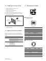
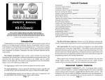
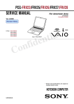
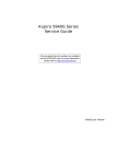
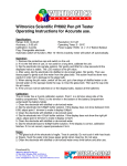
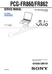
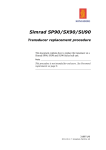
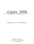
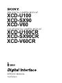
B/W DIGITAL CAMERA MODULE
XCD-U100
XCD-SX90
XCD-V60
XCD-U100CR
XCD-SX90CR
XCD-V60CR
COLOR DIGITAL CAMERA MODULE
SERVICE MANUAL
1st Edition
! WARNING
This manual is intended for qualified service personnel only.
To reduce the risk of electric shock, fire or injury, do not perform any servicing other than that
contained in the operating instructions unless you are qualified to do so. Refer all servicing to
qualified service personnel.
! WARNUNG
Die Anleitung ist nur für qualifiziertes Fachpersonal bestimmt.
Alle Wartungsarbeiten dürfen nur von qualifiziertem Fachpersonal ausgeführt werden. Um die
Gefahr eines elektrischen Schlages, Feuergefahr und Verletzungen zu vermeiden, sind bei
Wartungsarbeiten strikt die Angaben in der Anleitung zu befolgen. Andere als die angegeben
Wartungsarbeiten dürfen nur von Personen ausgeführt werden, die eine spezielle Befähigung
dazu besitzen.
! AVERTISSEMENT
Ce manual est destiné uniquement aux personnes compétentes en charge de l’entretien. Afin
de réduire les risques de décharge électrique, d’incendie ou de blessure n’effectuer que les
réparations indiquées dans le mode d’emploi à moins d’être qualifié pour en effectuer d’autres.
Pour toute réparation faire appel à une personne compétente uniquement.
XCD-U100/SX90/V60
XCD-U100CR/SX90CR/V60CR
Table of Contents
Manual Structure
3. Circuit Description
Purpose of this manual ................................................................. 3
3-1.
BI-217, BI-218, and BI-219 Boards ............................... 3-1
Related manuals ........................................................................... 3
3-2.
FM-96 Board .................................................................. 3-1
3-3.
IF-1068 Board ................................................................. 3-1
3-4.
CN-3020 Board ............................................................... 3-1
1. Service Overview
1-1.
Board Location ............................................................... 1-1
1-2.
Removing/Installing the Cabinet .................................... 1-1
4. Spare Parts
1-2-1.
1-2-2.
Upper case/Lower case .......................................... 1-1
Rear Panel Assembly ............................................ 1-2
4-1.
Notes on Repair Parts ..................................................... 4-1
4-2.
Exploded Views .............................................................. 4-2
1-2-3.
Front Panel Assembly ........................................... 1-2
4-3.
Packing Materials & Supplied Accessories .................... 4-4
1-3. Removing/Installing the Board ....................................... 1-3
1-3-1.
BI-217/218/219 Board ........................................... 1-3
1-3-2.
1-3-3.
FM-96 Board ......................................................... 1-3
DC-DC Converter ................................................. 1-4
1-3-4.
1-3-5.
IF-1068 Board ....................................................... 1-4
CN-3020 Board ..................................................... 1-5
1-4.
5. Block Diagram
Overall ............................................................................ 5-1
Lens Mount Cap, Filter Bracket, Optical Dust Cover
(XCD-V60/SX90/U100), Infrared Cut Filter (XCDV60CR/SX90CR/U100CR), Sealing Rubber ................. 1-6
1-5.
Round Type Connector (12-Pin) .................................... 1-7
1-6.
Matching Connectors and Cables ................................... 1-7
1-7.
Signal Inputs and Outputs ............................................... 1-7
1-8.
Unleaded Solder .............................................................. 1-8
6. Frame Wiring
Frame Wiring .................................................................. 6-1
2. Adjustment
2-1.
Writing of Serial Number and Node Unique ID ............. 2-1
2-2.
Camera Adjustment ........................................................ 2-2
2-2-1.
Black and White (B/W) Camera
(XCD-U100/SX90/V60) ....................................... 2-3
2-2-2.
Color Camera
(XCD-U100CR/SX90CR/V60CR) ....................... 2-4
XCD-U100/SX90/V60
XCD-U100CR/SX90CR/V60CR
1
Manual Structure
Purpose of this manual
This manual is the Service Manual of the B/W Digital Camera Module XCD-U100/
SX90/V60 and Color Digital Camera Module XCD-U100CR/SX90CR/V60CR.
This manual contains the service overview, adjustment, circuit description, spare
parts, block diagrams, and frame wiring.
The service of this unit is basically performed by the replacement of board.
Therefore, the schematic diagram, board layout and electrical parts list are not
contained.
Related manuals
In addition to this Service Manual the following manual is provided.
. “Operating Instructions” (supplied with this unit)
Part No.: 3-287-508-0X (Japanese, English)
3-287-508-1X (Korean)
This manual is necessary for application and operation of this unit.
. “Semiconductor Pin Assignments” CD-ROM (Available on request)
This “Semiconductor Pin Assignments” CD-ROM allows you to search for
semiconductors used in Broadcast and Professional equipment.
This manual contains a complete list of semiconductors and their ID Nos., and
thus should be used together with the CD-ROM.
Part number: 9-968-546-06
XCD-U100/SX90/V60
XCD-U100CR/SX90CR/V60CR
3
Section 1
Service Overview
1-1. Board Location
1-2. Removing/Installing the Cabinet
1-2-1. Upper case/Lower case
FM-96 board
CN-3020 board
1. Remove the seven screws, then remove the upper case
and lower case.
DC-DC converter
PM2 x 4
PM2 x 4
IF-1068 board
PM2 x 4
Upper case
BI-217/218/219 board
PM2 x 4
Board name
Model name
BI-217 board
XCD-V60
XCD-V60CR
BI-218 board
XCD-SX90
XCD-SX90CR
BI-219 board
XCD-U100
XCD-U100CR
CN-3020 board
Common
DC-DC converter
XCD-V60/V60CR/U100/U100CR
Lower case
XCD-SX90/SX90CR
FM-96 board
Refer to “Section 4 Spare Parts”
IF-1068 board
Common
2. Attach the upper case and lower case in the reverse
order of step 1.
XCD-U100/SX90/V60
XCD-U100CR/SX90CR/V60CR
1-1
1-2-2. Rear Panel Assembly
1-2-3. Front Panel Assembly
1. Remove the upper case and lower case.
(Refer to Section 1-2-1.)
2. Remove the two screws, then pull out the rear panel
assembly.
3. Disconnect the flexible flat cable from the connector
(CN900) on the CN-3020 board.
n
When replacing the front panel assembly, perform the
writing the serial number and Node Unique ID and camera
adjustment. For details, refer to Sections 2-1 and 2-2.
CN-3020 board
CN900
Flexible flat cable
1. Remove the upper case and lower case.
(Refer to Section 1-2-1.)
2. Remove the two screws, then pull out the front panel
assembly.
3. Disconnect the flexible flat cable from the connector
(CN101) on the BI-217/218/219 board.
PM2 x 4
Flexible flat
cable
Rear panel assembly
PM2 x 4
CN101
PM2 x 4
PM2 x 4
4. Attach the rear panel assembly in the reverse order of
steps 1 to 3.
n
When attaching the rear panel assembly, securely
attach it while pushing it against the chassis.
Chassis
Rear panel assembly
BI-217/218/219 board
Front panel assembly
This illustration is for XCD-SX90/SX90CR.
4. Attach the front panel assembly in the reverse order of
steps 1 to 3.
n
Front panel assembly
Chassis
When attaching the front panel assembly, securely
attach it while pushing it against the chassis.
1-2
XCD-U100/SX90/V60
XCD-U100CR/SX90CR/V60CR
1-3. Removing/Installing the Board
1-3-2. FM-96 Board
1-3-1. BI-217/218/219 Board
n
When replacing the FM-96 board, perform the writing of
the serial number and Node Unique ID. For details, refer to
Section 2-1.
1. Remove the upper case and lower case.
(Refer to Section 1-2-1.)
2. Remove the front panel assembly.
(Refer to Section 1-2-3.)
3. Remove the two screws.
4. Remove the solders of CCD, then remove the BI-217/
218/219 board.
. BI-217 board: 16 solders
. BI-218 board: 24 solders
. BI-219 board: 20 solders
Front panel assembly
CCD
BI-217/218/219 board
1. Remove the upper case and lower case.
(Refer to Section 1-2-1.)
2. Remove the rear panel assembly.
(Refer to Section 1-2-2.)
3. Remove the front panel assembly.
(Refer to Section 1-2-3.)
4. Disconnect the three flexible flat cables from the
connectors (CN200, CN400 and CN700) on the FM-96
board.
5. XCD-SX90/SX90CR:
Remove the three screws, then remove the shield sheet
and FM-96 board.
XCD-V60/V60CR/U100/U100CR:
Remove the three screws, then remove the FM-96
board.
PM2 x 4
PM2 x 4
Solders
This illustration is for XCD-V60/V60CR.
XCD-SX90/SX90CR
Shield sheet
5. Install the BI-217/218/219 board in the order of steps
3, 4, 2 and 1.
CN700
CN200
FM-96 board
CN400
Flexible flat
cables
Flexible flat cable
6. Install the FM-96 board in the reverse order of steps 1
to 5.
XCD-U100/SX90/V60
XCD-U100CR/SX90CR/V60CR
1-3
1-3-3. DC-DC Converter
1-3-4. IF-1068 Board
1. Remove the upper case and lower case.
(Refer to Section 1-2-1.)
2. Remove the rear panel assembly.
(Refer to Section 1-2-2.)
3. Remove the front panel assembly.
(Refer to Section 1-2-3.)
4. Remove the FM-96 board. (Refer to Section 1-3-2.)
5. Disconnect the two flexible flat cables from the
connectors (CN001 and CN002) on the DC-DC
converter.
6. Remove the three screws 1, then remove the DC-DC
converter in the direction of the arrow.
7. Remove the two screws 2, then remove the board
support.
1. Remove the upper case and lower case.
(Refer to Section 1-2-1.)
2. Remove the rear panel assembly.
(Refer to Section 1-2-2.)
3. Remove the front panel assembly.
(Refer to Section 1-2-3.)
4. Remove the FM-96 board. (Refer to Section 1-3-2.)
5. Remove the DC-DC converter.
(Refer to Section 1-3-3.)
6. Disconnect the three flexible flat cables from the
connectors (CN800, CN801 and CN802) on the IF1068 board.
7. Remove the three screws, then remove the IF-1068
board in the direction of the arrow.
8. Remove the two shield plates (connector).
Screws 2
(PM2 x 4)
CN001
CN002
Flexible flat cable
Screw 1
(PM2 x 4)
DC-DC
converter
Shield plates
(connector)
Flexible flat cable
CN800
PM2 x 4
CN802
Flexible flat cable
IF-1068 board
Board support
Screw 1
(PM2 x 4)
Flexible flat cable
CN801
Flexible flat cable
Screw 1
(PM2 x 4)
8. Attach the DC-DC converter in the reverse order of
steps 1 to 7.
1-4
9. Install the IF-1068 board in the reverse order of steps 1
to 8.
XCD-U100/SX90/V60
XCD-U100CR/SX90CR/V60CR
1-3-5. CN-3020 Board
1. Remove the upper case and lower case.
(Refer to Section 1-2-1.)
2. Remove the rear panel assembly.
(Refer to Section 1-2-2.)
3. Remove the twelve solders of the connector from the
CN-3020 board.
4. Remove the screw, then remove the CN-3020 board.
Rear panel assembly
Solders
PM2 x 4
CN-3020 board
5. Install the CN-3020 board in the reverse order of steps
1 to 4.
XCD-U100/SX90/V60
XCD-U100CR/SX90CR/V60CR
1-5
1-4. Lens Mount Cap, Filter Bracket, Optical Dust Cover (XCD-V60/SX90/
U100), Infrared Cut Filter (XCD-V60CR/SX90CR/U100CR), Sealing Rubber
1. Remove the upper case and lower case.
(Refer to Section 1-2-1.)
2. Remove the front panel assembly. (Refer to Section 1-2-3.)
3. Remove the lens mount cap.
4. XCD-V60/SX90/U100:
Remove the two screws (M1.7 x 4), then remove the
filter bracket and optical dust cover.
XCD-V60CR/SX90CR/U100CR:
Remove the two screws (M1.7 x 4), then remove the
filter bracket and infrared cut filter.
5. Remove the two screws (M1.7 x 4).
n
When attaching the screws, attach the screw 1 first
and then 2.
6. Remove the two screws (PM2 x 4), then remove the
BI-217/218/219 board and spacers.
n
When attaching the spacers, be sure to attach them
back to the original positions.
7. Remove the sealing rubber.
8. Attach the lens mount cap, filter bracket, optical dust
cover, infrared cut filter and sealing rubber in the
reverse order of steps 1 to 7.
Note for attaching the infrared cut filter
(XCD-V60CR/SX90CR/U100CR)
Attach the infrared cut filter so that its evaporation surface
is placed on the side of BI-217/218/219 board.
Evaporation surface checking method
When you put the cotton-tipped swab on the surface of the
infrared cut filter, the image of the cotton-tipped swab is
reflected as if the tips contact each other (state being
reflected in a mirror) if it is the evaporation surface.
Evaporation
surface
Image of
cotton-tipped
swab
2
PM2 x 4
BI-217/218/219 board M1.7 x 4
Spacers
Image that is reflected as
if the tips contact each other
Cotton-tipped
swab
Infrared cut filter
Sealing rubber
1
M1.7 x 4
Spacers
Evaporation
surface
XCD-V60/SX90/U100
Note for attaching the sealing rubber
Attach the sealing rubber to the boss side with its chamfered portion placed upward.
(Refer to the illustration on the left.)
Lens mount cap
Boss
Front panel
Optical dust cover
Filter bracket
M1.7 x 4
XCD-V60CR/SX90CR/U100CR
Lens mount cap
Front panel
Infrared cut filter
Filter bracket
M1.7 x 4
1-6
XCD-U100/SX90/V60
XCD-U100CR/SX90CR/V60CR
1-5. Round Type Connector (12-Pin)
1-7. Signal Inputs and Outputs
2
1. Remove the upper case and lower case.
(Refer to Section 1-2-1.)
2. Remove the rear panel assembly.
(Refer to Section 1-2-2.)
3. Remove the CN-3020 board. (Refer to Section 1-3-5.)
4. Remove the nut and washer, then remove the round
type connector (12-pin).
Rear panel
1
1 IEEE1394b connector
. IEEE1394b-2002
9
Washer
5
Round type
connector (12-pin )
Nut
1
5. Attach the round type connector (12-pin) in the reverse
order of steps 1 to 4.
1-6. Matching Connectors and Cables
When external cables are connected to the connector of
each unit, the hardware listed below (or equivalents) must
be used.
Connector
Matching connector/cable
IEEE1394b
IEEE1394b cable (9P-9P)
(Commercially available products)
IEEE1394b cable (9P-6P)
(Commercially available products)
DC IN
4
— External view —
Pin No.
Signal name
Remarks
1
TPB (_)
Twisted pair B (_)
2
TPB (+)
Twisted pair B (+)
3
TPA (_)
Twisted pair A (_)
4
TPA (+)
Twisted pair A (+)
5
TPA (R)
Twisted pair A (Ground reference)
6
VG
Power ground
7
N.C.
8
VP
Power voltage input
9
TPB (R)
Twisted pair B (Ground reference)
2 DC IN: 12-pin (male)
Camera cable
CCXC12P02N (2 m)
CCXC12P02N (5 m)
CCXC12P02N (10 m)
CCXC12P02N (25 m)
1 9
2 !/ 8
3 !- != 7
4
6
5
— External view —
XCD-U100/SX90/V60
XCD-U100CR/SX90CR/V60CR
Pin No.
Signal
Pin No.
Signal
1
POWER_GND
7
GPIO_IN2
2
POWER_IN
8
GPIO_OUT2_
3
ISO_GND
9
GPIO_OUT2+
4
STROBE_OUT
10
GPIO_IN1
5
GPIO_OUT1_
11
TRIGGER_IN
6
GPIO_OUT1+
12
ISO_GND
1-7
1-8. Unleaded Solder
Boards requiring use of unleaded solder are printed with a
lead free mark (LF) indicating the solder contains no
lead.(Caution: Some printed circuit boards may not come
printed with the lead free mark due to their particular size.)
: LEAD FREE MARK
m
. Be sure to use the unleaded solder for the printed circuit
board printed with the lead free mark.
. The unleaded solder melts at a temperature about 40 dC
higher than the ordinary solder, therefore, it is recommended to use the soldering iron having a temperature
regulator.
. The ordinary soldering iron can be used but the iron tip
has to be applied to the solder joint for a slightly longer
time. The printed pattern (copper foil) may peel away if
the heated tip is applied for too long, so be careful.
1-8
XCD-U100/SX90/V60
XCD-U100CR/SX90CR/V60CR
Section 2
Adjustment
2-1. Writing of Serial Number and Node
Unique ID
2. Click the “Adjust” tab and “Enter Adjust mode” tab.
The unit enters the adjustment mode.
Adjust tab
n
Perform the writing when replacing the FM-96 board or
front panel assembly.
Required equipment
.
.
.
.
Personal computer (PC)
IEEE1394.b board
IEEE1394b cable (Commercially available products)
IIDC_CAM**** software: J-7120-410-A
(**** represents the version number.)
xxxxxxxx
xxxxxxxx
xx
3. Check the model nameplate on the bottom of this unit.
Type the Node Unique ID in the Node Unique ID box
and type the serial number in the Serial Number box.
Connection
Lens side
Camera
IEEE1394b
Serial
number
Model nameplate affixed
to the bottom of this unit
No.
Personal computer
Node Unique ID
Node Unique ID
IEEE1394b
cable
Rear side
[Write] button
Preparation
1. Connect each device as shown in the above illustration.
2. Install the IIDC control software in an arbitrary place
of PC.
xxxxxxxx
Procedure
xxxxxxxx
xx
1. Start the IIDC_CAM****software.
The IIDC control window is displayed.
Type the serial number.
Type the Node Unique ID.
4. Click the [Write] button.
xxxxxxxx
xxxxxxxx
xx
XCD-U100/SX90/V60
XCD-U100CR/SX90CR/V60CR
2-1
5. Click the “Flash” tab.
6. Click the [Restart|the|Camera] button to restart.
Flash tab
2-2. Camera Adjustment
n
Perform the adjustment when replacing the front panel
assembly.
Required equipment
[Restart|the|Camera] button
7. Check if the serial number and Node Unique ID on the
model nameplate correspond to each number in the
IIDC control window. If not, perform the procedure
from step 1 again.
. Personal computer (PC)
. IEEE1394b cable(Commercially available products)
. IIDC_CAM**** software:
J-7120-410-A
(**** represents the version number.)
. Pattern box PTB-700:
J-6431-850-A
. Clear chart (manufactured by Kenko): J-6080-621-A
. C-mount lens VF2509 (Canon) or equivalent
Connection
Clear chart
Camera
Pattern box
PTB-700
C-mount
lens
IEEE1394b
Personal computer
IEEE1394b
cable
Preparation
1. Connect each device as shown in the above illustration.
2. Install the IIDC_CAM**** software in an arbitrary
place of PC.
2-2
XCD-U100/SX90/V60
XCD-U100CR/SX90CR/V60CR
2-2-1. Black and White (B/W) Camera
(XCD-U100/SX90/V60)
1. Shoot the pattern box in the center of the window
through the clear chart at the wide end.
2. Start the IIDC_CAM**** software.
3. Click WFM (Waveform Monitor) in the menu.
The waveform is displayed.
WFM
6. Click the Exposure tab and adjust the shutter in the
window so that the Green level reaches close to 100%
(does not exceed 100% (236)) in the WFMwindow.
The shutter value (reference value) at which the Green
level reaches close to 100% on WFM is as follows.
XCD-V60: 13
XCD-SX90: 19
XCD-U100: 19
Exposure tab
Green level
4. Start the IIDC_CAM**** software.
The IIDC control window is displayed.
xxxxxxxx
7. Click the “Adjust” tab in the IIDC control window.
[Write] button
xxxxxxxx
xx
xxxxxxxx
5. Set the lens iris to F1.4. (Zoom at the full angle of
field)
xxxxxxxx
xx
[Gain0dB] button
8. Click the [Gain0dB] button.
The Gain 0dB adjustment is performed.
9. Check that the adjustment level (Y) satisfies the
specification A.
A = 235 ± 1 step
n
If the specification A is not satisfied, perform the
procedure from step 1 again.
10. After the adjustment is completed, click the [Write]
button and write the adjustment value.
XCD-U100/SX90/V60
XCD-U100CR/SX90CR/V60CR
2-3
2-2-2. Color Camera
(XCD-U100CR/SX90CR/V60CR)
Green level
1. Shoot the pattern box in the center of the window
through the clear chart at the wide end.
2. Start the IIDC_CAM**** software.
3. Click WFM (Waveform Monitor) in the menu.
The waveform is displayed.
WFM
7. Click the “Adjust” tab in the IIDC control window.
[AdjustWB] button
xxxxxxxx
[Write] button
xxxxxxxx
xx
4. Start the IIDC_CAM**** software.
The IIDC control window is displayed.
xxxxxxxx
xxxxxxxx
xx
5. Set the lens iris to F1.4. (Zoom at the Tele end)
6. Click the Exposure tab and adjust the shutter in the
window so that the Green level reaches close to 100%
(does not exceed 100% (236)) in the WFM window.
The shutter value (reference value) at which the Green
level reaches close to 100% on WFM is as follows.
XCD-V60CR: 28
XCD-SX90CR: 41
XCD-U100CR: 36
Exposure tab
2-4
[Gain0dB] button
8. Click the [AdjustWB] button to adjust the color.
9. Click the [Gain0dB] button.
The Gain 0dB adjustment is performed.
10. Check that the adjustment level satisfies the specification A.
A = 235 ± 1 step
n
If the specification A is not satisfied, perform the
procedure from step 1 again.
11. After the adjustment is completed, click the [Write]
button and write the adjustment value.
12. Click the [AdjustWB] button.
The WB adjustment is performed.
13. Check that the adjustment level satisfies the specification B.
B = 235 ± 1 step
n
If the specification B is not satisfied, perform the
procedure from step 1 again.
14. After the adjustment is completed, click the [Write]
button and write the adjustment value.
XCD-U100/SX90/V60
XCD-U100CR/SX90CR/V60CR
Section 3
Circuit Description
3-1. BI-217, BI-218, and BI-219 Boards
3-3. IF-1068 Board
These boards consist of CCD (IC101) and ADC (BI-217:
IC105), BI-218: IC102), and BI-219: IC105) that are used
for VGA color/black & white (BI-217), SXGA color/black
& white (BI-218), and UXGA color/black & white (BI219).
CCD is driven using the power, communication
(AD_SCK/SL/SDATA), sync signal (AD_CLK/HD/VD),
and CCD vertical drive pulses sent from the FM-96 board
and using the CCD horizontal drive pulse generated by an
analog-to-digital converter (ADC). CCD analog data is
input to ADC and output to FPGA on the FM-96 board as
digital data so as to produce an LVDS signal through CDS/
GAIN/CLAMP/AD conversion in ADC
This board consist of an oscillator (X800), an
IEEE1394PHY layer (IC803), 1394 connectors (CN803
and CN804), and an external input signal isolation circuit
(consisting of PH800, PH801, and PH802).
A power signal is input from a DC-DC converter through
the flexible wiring board of CN802. It also plays the part
for transferring the original power to the DC-DC converter.
Image data is input from the LINK layer of the FM-96
board to the PHY layer and output to the connected
connectors (CN803 and CN804) as a differential signal of
800/400 MHz. The control data from host PC is input
from a 1394 connector as a differential signal, and simultaneously, power is also supplied from the 1394 connector.
The external input signal input from the CN-3020 board is
passed through an external input signal isolation circuit
and sent to FPGA on the FM-96 board.
X800 is sent to the PHY and FM-96 board because it is
used as the clock of a 1394 system and used in the CPU/
1394 module inside FPGA.
3-2. FM-96 Board
This board consists of an oscillator (X200), FPGA (IC201:
TG/DSP/CPU/SDRAM controller incorporating an
IEEE1394LINK, a, b-compatible layer), SDRAM (IC301)
for image saving, SDRAM (IC502) for CPU execution,
EEPROM (IC402) for camera parameter saving, a V driver
(IC200), flash (IC503) for FPGA data saving, and an
FPGA write connector (CN500). A power pulse is input
from a DC-DC converter through the flexible wiring board
of connector CN101.
The image data of an LVDS signal is input from CN200 to
FPGA as a flow of image data, passed through DSP and
image SDRAM, and converted into a 1394 packet using a
1394LINK layer. The converted data is output through
CN801 to the 1394PHY layer on the IF-1068 board.
Two-way communication is done in the block related to a
1394 system. Image data is not only output, but also the
control data from the host is input. The control data is
saved in the register of a LINK layer. Internal CPU
interprets instructions and sets them to the internal module
of FPGA.
CN801 is also used as the interface of the external input/
output signal from CN901 on the CN-3020 board.
XCD-U100/SX90/V60
XCD-U100CR/SX90CR/V60CR
3-4. CN-3020 Board
This board consists of a 12-pin connector (CN901) for an
external input/output signal and external power, and an
external output signal isolation circuit (PH901 and
PH902).
External power is used to compensate for the insufficient
power supply on the host side during multiple daisy-chain
connections.
3-1
Section 4
Spare Parts
4-1. Notes on Repair Parts
1. Safety Related Components Warning
w
Components marked ! are critical to safe operation.
Therefore, specified parts should be used in the case of
replacement.
2. Standardization of Parts
Some repair parts supplied by Sony differ from those
used for the unit. These are because of parts commonality and improvement.
3. Stock of Parts
Parts marked with “o” at SP (Supply Code) column of
the spare parts list may not be stocked. Therefore, the
delivery date will be delayed.
4. Harness
Harnesses with no part number are not registered as
spare parts.
XCD-U100/SX90/V60
XCD-U100CR/SX90CR/V60CR
4-1
Overall Block
4-2. Exploded Views
22
22
22
14
C
A
22
22
23
F900
12
2
13
E
10
22
7
9
16
F
8
22
25
12
F800
17
22
4
22
E
3
11
24
D
22
B
G
F
H
22
18
1
C
15
20
A
G
D
6
H
21
B
18
19
5
XCD-V60
XCD-SX90
XCD-U100
6
XCD-V60CR
XCD-SX90CR
XCD-U100CR
4-2
XCD-U100/SX90/V60
XCD-U100CR/SX90CR/V60CR
Overall Block
No.
Part No.
1
SP Description
A-1441-025-A s MOUNTED CIRCUIT BOARD,
(FOR XCD-V60/V60CR)
A-1441-026-A s MOUNTED CIRCUIT BOARD,
(FOR XCD-SX90/SX90CR)
A-1441-027-A s MOUNTED CIRCUIT BOARD,
(FOR XCD-U100/U100CR)
A-1441-028-A s MOUNTED CIRCUIT BOARD,
(FOR XCD-V60)
A-1441-030-A s MOUNTED CIRCUIT BOARD,
(FOR XCD-SX90)
A-1441-031-A s MOUNTED CIRCUIT BOARD,
(FOR XCD-SX90CR)
A-1441-032-A s MOUNTED CIRCUIT BOARD,
(FOR XCD-U100)
A-1441-033-A s MOUNTED CIRCUIT BOARD,
(FOR XCD-U100CR)
A-1466-674-A s MOUNTED CIRCUIT BOARD,
(FOR XCD-V60CR)
A-1441-034-A s MOUNTED CIRCUIT BOARD,
A-1441-035-A s MOUNTED CIRCUIT BOARD,
A-1466-663-A s PANEL ASSY (RP), FRONT
A-1466-746-A s PANEL ASSY (RP), FRONT
A-1466-748-A s PANEL ASSY (RP), FRONT
A-1466-768-A s PANEL ASSY (RP), FRONT
A-1466-769-A s PANEL ASSY (RP), FRONT
A-1466-771-A s PANEL ASSY (RP), FRONT
2
3
4
5
6
BI-217
BI-218
BI-219
FM-96 V60
FM-96 SX90
FM-96 SX90CR
FM-96 U100
FM-96 U100CR
FM-96 V60CR
IF-1068
CN-3020
(FOR XCD-V60)
(FOR XCD-V60CR)
(FOR XCD-SX90)
(FOR XCD-SX90CR)
(FOR XCD-U100)
(FOR XCD-U100CR)
8
9
10
1-251-887-11 s COVER, OPTICAL DUST
(FOR XCD-V60/SX90/U100)
1-547-185-51 o FILTER, INFRARED CUT
(FOR XCD-V60CR/SX90CR/U100CR)
1-480-424-11 s CONVERTER, DC-DC
(FOR XCD-V60/V60CR/U100/U100CR)
1-480-424-21 s CONVERTER, DC-DC (FOR XCD-SX90/SX90CR)
1-691-410-31 s CONNECTOR, ROUND TYPE 12P
1-831-171-11 s CABLE, FLEXIBLE FLAT (14 CORE)
1-834-991-11 s CABLE, FLEXIBLE FLAT (40 CORE)
11
12
13
14
15
1-834-992-11
1-834-993-11
3-287-055-01
3-287-057-01
3-287-058-01
s
s
s
s
s
16
17
18
19
20
3-287-629-01
3-287-630-01
3-303-809-81
3-622-446-01
3-863-430-01
s
s
s
s
s
21
22
23
24
25
3-863-431-01
3-968-729-71
3-398-173-01
3-398-174-01
3-398-175-01
s
s
s
s
s
7
F800
F900
CABLE, FLEXIBLE FLAT (30 CORE)
CABLE, FLEXIBLE FLAT (20 CORE)
PANEL, REAR
CASE, UPPER
CASE, LOWER
PLATE,SHIELD (CONNECTOR)
SHEET, PROTECTION
SCREW (M1.7X4), SPECIAL HEAD
CAP,LENS MOUNT(FOR C MOUNT)
RUBBER,SEAL
(FOR XCD-SX90/SX90CR/U100/U100CR)
3-992-901-01 s RUBBER,SEAL (FOR XCD-V60/V60CR)
!
!
BRACKET,FILTER
SCREW (M2), LOCK ACE, P2
SHIELD SHEET (FOR XCD-SX90/SX90CR)
MG SHEET A (FOR XCD-SX90/SX90CR)
MG SHEET A (FOR XCD-SX90/SX90CR)
1-533-998-21 s FUSE, (SMD) (1A/125V)
1-533-998-21 s FUSE, (SMD) (1A/125V)
XCD-U100/SX90/V60
XCD-U100CR/SX90CR/V60CR
4-3
4-3. Packing Materials & Supplied
Accessories
---------------------------------------PACKING MATERIALS & SUPPLIED ACCESSORIES
---------------------------------------Ref. No.
or Q'ty Part No.
SP Description
1pc
!
1pc
!
4-4
3-287-508-01 s MANUAL, INSTRUCTION
(JAPANESE,ENGLISH)
3-287-508-11 s MANUAL, INSTRUCTION
(KOREAN)
XCD-U100/SX90/V60
XCD-U100CR/SX90CR/V60CR
Overall
Overall
Section 5
Block Diagram
BI-217 BOARD (VGA)
BI-218 BOARD (SXGA)
BI-219 BOARD (UXGA)
IC101
IC102 (BI-218 BOARD)
IC105 (BI-217/219 BOARD)
CCD
14-BIT CCD
SIGNAL
PROCESSOR
IF-1068 BOARD
FM-96 BOARD
IC201
IC803
4
DOUT0N
DOUT0P
DOUT1N
DOUT1P
CLK_P
CLK_N
18
PHY-IF
THREE-PORT
CABLE
TRANSCEIVER/
ARBITER
S800
1394
X800
98.301MHz
6
S800
IC800-IC802
PH800-PH803
6
AD_HD
AD_VD
SCK
SDATA
SL
GPIO
PHOTOCOUPLER
DC IN
1394
6
PH901, PH902
PHOTOCOUPLER
IC301
FPGA
5
32
SDRAM
(4MB x32)
SD_D0-D31
IC200
IC502
10
V_TO1-TO6
V_BO1-BO4
VERTICAL
DRIVER FOR
CCD SENSORS
18
16
+3.3V_IF
+1.95V_IF
+ISO_5V
SDRAM
(16MB)
P_D0-D15
IC503
X200
36.000MHz
(XCD-U100/U100CR,
XCD-V60/V60CR)
49.302MHz
(XCD-SX90/SX90CR)
+3.3V_FM
+1.95V_BI
+5V/+3.6V_BI
+15V_BI
_7.5V/_8.5V_BI
CN-3020
BOARD
16
P_D0-D15
IC402
EEPROM
(256kBIT)
FLASH MEMORY
(2MB)
+3.3V_FM
+15V_BI
_7.5V/_8.5V_BI
+1.3V_FM
+1.95V_BI
+5V/+3.6V_BI
+3.3V_IF
+1.95V_IF
+ISO_5V
+3.3V_FM
+15V_BI
_7.5V/_8.5V_BI
+1.3V_FM
+1.95V_BI
+5V/+3.6V_BI
DC-DC CONVERTER
Overall
XCD-U100/SX90/V60
XCD-U100CR/SX90CR/V60CR
5-1
5-1
Frame Wiring
Frame Wiring
Section 6
Frame Wiring
CN101
CN200
CN400
FLEXIBLE
FLAT
CABLE
CN901
DC IN
LENS
BI-217 (XCD-V60/V60CR)
BI-218 (XCD-SX90/SX90CR)
BI-219 (XCD-U100/U100CR)
CN500
CN700
CN900
FM-96
JTAG
CN-3020
FLEXIBLE
FLAT
CABLE
CN001
FLEXIBLE
FLAT
CABLE
FLEXIBLE
FLAT
CABLE
CN002
DC-DC CONVERTER
FLEXIBLE
FLAT
CABLE
CN801
CN802
CN800
CN803
IEEE1394b
CN804
IEEE1394b
IF-1068
XCD-U100/SX90/V60
XCD-U100CR/SX90CR/V60CR
Frame Wiring
6-1
6-1
XCD-U100 (SY)
XCD-U100CR (SY)
XCD-SX90 (SY)
XCD-SX90CR (SY)
XCD-V60 (SY)
XCD-V60CR (SY) E
9-968-402-01
Sony Corporation
Printed in Japan
2007. 12 22
©2007