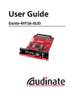
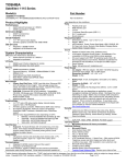
1
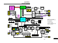
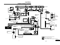
PCG-GRV550
SERVICE MANUAL
For American Area
US Model
Canadian Model
Ver 1-2002J
Revision History
Lineup : PCG-GRV550
l
a
i
t
S400
n
e
d
i
f
n
o
C
• Design and specifications are subject to
change without notice.
NOTEBOOK COMPUTER
9-876-031-01
Information in this document is subject to change without notice.
Caution Markings for Lithium/Ion Battery - The following or similar
texts shall be provided on battery pack of equipment or in both the
Sony, VAIO and CLIE are trademarks or registered trademarks of
Sony. Microsoft, Windows, Windows Media, Outlook, Bookshelf
operating and the service instructions.
and other Microsoft products are trademarks or registered trademarks
of Microsoft Corporation in the United States and other countries.
CAUTION: Danger of explosion if battery is incorrectly replaced.
Replace only with the same or equivalent type recommended by
The word Bluetooth and the Bluetooth logo are trademarks of
Bluetooth SIG, Inc. AMD, AMD logo, AMD Duron and
the manufacturer. Discard used batteries according to the
manufacturer’s instructions.
combinations thereof, 3DNow!, are trademarks of Advanced Micro
Devices, Inc. Intel Inside logo, Pentium and Celeron are trademarks
CAUTION: The battery pack used in this device may present a fire
or registered trademarks of Intel Corporation. Transmeta, the
Transmeta logo, Crusoe Processor, the Crusoe logo and
or chemical burn hazard if mistreated. Do not disassemble, heat
above 100°C (212°F) or incinerate.
combinations thereof are trademarks of Transmeta Corporation in
the USA and other countries. Graffiti, HotSync, PalmModem, and
Dispose of used battery promptly.
Keep away from children.
Palm OS are resistered trademarks, and the Hotsync logo and Palm
are trademarks of Palm, Inc. or its subsidiaries. (M) and Motrola
CAUTION: Changing the back up battery.
are trademarks of Motrora, Inc. Other Motrola products and services
with (R) mark like Dragomball are the trademarks of Motrola, Inc.
• Overcharging, short circuiting, reverse charging, multilation or
incineration of the cells must be avoided to prevent one or more of
All other names of systems, products and services in this manual
the following occurrences; release of toxic materials, release of
hydrogen and/or oxygen gas, rise in surface temperature.
are trademarks or registered trademarks of their respective owners.
In this manual, the (TM) or (R) mark are not specified.
• If a cell has leaked or vented, it should be replaced immediately
while avoiding to touch it without any protection.
Service and Inspection Precautions
1. Obey precautionary markings and instructions
4. Inspect after completing service
Labels and stamps on the cabinet, chassis, and components identify areas
requiring special precautions. Be sure to observe these precautions, as well
as all precautions listed in the operating manual and other associated
documents.
After servicing, inspect to make sure that all screws, components, and wiring
have been returned to their original condition. Also check the area around
the repair location to ensure that repair work has caused no damage, and
confirm safety.
2. Use designated parts only
5. When replacing chip components...
The set’s components possess important safety characteristics, such as
noncombustibility and the ability to tolerate large voltages. Be sure that
replacement parts possess the same safety characteristics as the originals.
Also remember that the 0 mark, which appears in circuit diagrams and
parts lists, denotes components that have particularly important safety
functions; be extra sure to use only the designated components.
Never reuse components. Also remember that the negative side of tantalum
capacitors is easily damaged by heat.
3. Always follow the original design when mounting
parts and routing wires
6. When handling flexible print boards...
• The temperature of the soldering-iron tip should be about 270C.
• Do not apply the tip more than three times to the same pattern.
• Handle patterns with care; never apply force.
The original layout includes various safety features, such as inclusion of
insulating materials (tubes and tape) and the mounting of parts above the
printer board. In addition, internal wiring has been routed and clamped so
as to keep it away from hot or high-voltage parts. When mounting parts or
routing wires, therefore, be sure to duplicate the original layout.
Caution: Remember that hard disk drives are easily damaged by
vibration. Always handle with care.
ATTENTION AU COMPOSANT AYANT RAPPORT
À LA SÉCURITÉ!
LES COMPOSANTS IDENTIFÉS PAR UNE MARQUE 0 SUR LES
DIAGRAMMES SCHÉMATIQUES ET LA LISTE DES PIÈCES SONT
CRITIQUES POUR LA SÉCURITÉ DE FONCTIONNEMENT. NE
REMPLACER CES COMPOSANTS QUE PAR DES PIÈSES SONY
DONT LES NUMÉROS SONT DONNÉS DANS CE MANUEL OU
DANS LES SUPPÉMENTS PUBLIÉS PAR SONY.
Confidential
—2—
PCG-GRV550 (AM)
TABLE OF CONTENTS
Section
Title
Page
CHAPTER 1. BLOCK DIAGRAM ............................... 1-1
(to 1-2)
CHAPTER 2. FRAME HARNESS DIAGRAM ........ 2-1
(to 2-2)
CHAPTER 3. EXPLODED VIEWS AND
PARTS LIST ............................................ 3-1
3-1. Main Section .................................................................... 3-3
3-2. LCD Section – Made by SH – ........................................ 3-7
(to 3-8)
CHAPTER 4. OTHERS
4-1. Replacing the CPU .......................................................... 4-1
1. Removing the CPU .......................................................... 4-1
2. Installing the CPU ............................................................ 4-1
History of the changes is shown as the
“Revision History” at the end of this data.
Confidential
—3—
PCG-GRV550 (AM)
CHAPTER 1.
BLOCK DIAGRAM
Pentium 4
Processor
512KB L2
478pins
uFCPGA
CPU Local Bus
DDR(SO-DIMM)
USB Left
CONN
Port-3
Port-3
UAX: DDR200 256MB x
EAX: DDR200 256MB x
TV-Out
AV
Out
Cable
Audio-Out
2
1
VGA DSUB-15
Graphics
Port-2
Port-2
USB2
16.0inch SXGA
SMBUS2
Refer to Clock Generator
LCD CONN
BlockDiagram
AGP x 4
Port-0
USB3
CLKGEN
IMI
9870GTD
SMBUS2
SONY
USB Right
CONN
USB Rear
CONN
200MHz Memory Bus
(DDR)
Memory
CONTROLLER
HUB (MCH) 845MZ
593 FCBGA
TV-Out
M7-32CL
(ATI)
Port-1
i.LINK
i.LINK0
TV-Out
Reserved
Dock-VGA DB-1
5
Port-5
S-Video-Out
Reserved
PCI BUS(3.3V
)
ForSPD
ForSPD
EEPROM
On DIMM1
EEPROM
On DIMM2
Port0-5
IO Control Hub
ICH3-m
FW82801CAM
SMBUS2
Ether
PHY
IDE(ATA100)
CARDBUS
& i.LINK
RICOH
R5C552
EEPROM
For LAN
For VID
EEPROM
Primary
EEPROM
EEPROM
For Password
ForClockGEN
RJ45
RJ-45
RJ11
RJ-11
Bus #2 Dev #5
For i.LINK
EEPROM
Secondary
Internal
HDD
RJ-45
Difference from GRX:
1. CPU PowerCircuit (with
PowerLimitter)
2. Gfx M7CL32
3. Chipset 845MZ
4. Remove MS/JOG/PortRi
5. LCD 16.0 SXG
CardBus/16bitCard
PC Card
Connector
2 Slot
i.LINK0
LPC
AC LINK
SM BUS1
Multi Purpose Bay
SMBUS0
ATF0
k
ea
ut
ATF1
Parallele
er
1st
Battery
FAN1
Sp
Power
Circuit
w/Power
Limiter
LPC47N227
H8S/2149
KBC/EC
SPIC
FAN0
MIC
DC Jack
BATTERY2
Super I/O
SMsC
LID
e
phon
Head
DCin
MDC
(Mobile
Daughter
Card)
Modem
Audio
YMF753
(Yamaha)
Line O
2nd
Battery
Optical
Drive
(Combo)
FWH
8Mb
(Flash BIOS
ROM)
I/O Expander
& SM BUS MUX
Other
Control
AMP, etc.
RJ-11
BATTERY1
BATTERY2
BATTERY1
LINE-OUT
PHONE
OUT
MIC
IN
Speaker
L&R
Internal KeyBoard
Membrane
TouchPad
Parallele
Parallele
Confidential
1-1
1-2
(END)
PCG-GRV550 (AM)
CHAPTER 2.
FRAME HARNESS DIAGRAM
AV OUT
USB
PHONE
PRINTER
NETWORK
MONITOR
DC-IN
Rear Panel
LCD
CN1111
2
1
14
1
13
CN1126
CN2009
2
2
199
20
2
HARD DISK
CN501
200
1
CN6002
SPEAKER
39
12
59
60
1
40
2
1
50
49
40
2
CN3102
2
2
PWS-25 Board
(Side-B)
1
CN2301
1
CN8002
20
KEY BOARD
1
4
2
2
FFC
4
CN3103
1
77
19
CNX-194 Board
(Side-A)
1
1
3
1
R Side
CN2201
24
1
HEADPHONE
44
200
43
199
EXTERNAL
MICROPHONE
CN502
CN1901
CN1202
RAM
13
14
PC CARD
CONNECTOR
USB
CN5500
CPU
14
1
154
CN5602
DDR200 SO-DIMM
256MB
NICKEL HYDROGEN
BATTERY
1
CN5540 CN5530 CN5510
1
11
2
12
2
1
78
2
CN2007
IEEE 1394 i.LINK
DC FAN
CN101
2nd FAN
CN853
2
CN2005
1
1 1
MBX-79 Board
(Side-A)
CN1124
11
2
2
CN5601
12
CN3501
CN1501
1
USB
CN851
CN852 39
40
CN1801
12
1
J1
30
29
CNX-195 Board
(Side-A)
FFC
CN5603
L Side
1
CN3101
CN855
2
J2
MODEM
CARD
12
2
30
2
1
LCD HARNESS
1
CN1125
29 CN1601
CN5002
HARNESS (2P)
CN5001
INVERTER
2 1
CNX-193 Board
(Side-A)
RAM
CN8401
LEX-41 Board
(Side-A)
10
CN8402
1
CN7502
SWX-125 Board
(Side-A)
CNX-196 Board
(Side-A)
DDR200 SO-DIMM
256MB
2nd BATTERY PACK
(OPTION)
CN7501
60
Combination
DRIVE
59
39
2
CN8001
1
CN6001
1
1
CN4001
1
12
J1
TOUCH PAD
BATTERY PACK
From board to connector (direct connection)
Harness (connector at both end)
Harness (soldered at one end)
Connectors soldered on board and appearing on the panel
Confidential
2-1
2-2
(END)
PCG-GRV550 (AM)
CHAPTER 3.
EXPLODED VIEWS AND PARTS LIST
NOTE:
• Items marked “ * ” are not stocked since they are seldom
required for routine service. Some delay should be
anticipated when ordering these items.
• The mechanical parts with no reference number in the
exploded views are not supplied.
• When two or more parts are shown in parallel, use the
part described first as the main part.
• The parts marked “ $ ” are the High Value Modules.
• The parts marked “ # ” are the parts on which
barcode label is attached.
The components identified by mark 0 or
dotted line with mark 0 are critical for safety.
Replace only with part number specified.
Les composants identifiés par une marque
0 sont critiques pour la sécurité.
Ne les remplacer que par une pièce portant
le numéro spécifié.
Confidential
3-1
3-2
PCG-GRV550 (AM)
3-1. Main Section
Ref.No.
1
2
3
4
5
Part No.
4-660-888-01
1-796-166-21
X-4625-380-1
4-660-904-01
4-660-906-13
Description
ESCUSHON TACHPAD
PAD, TOUCH
ASSY HOUSING PALMREST H
CUSHION PALMREST
SPRING BLIND
6
7
*8
9
10
4-668-482-01
4-660-900-02
4-660-901-01
1-761-518-11
4-668-317-01
SPRING (BLIND) (R)
PLATE ARM LEFT
PLATE ARM RIGHT
PWB, FLEXIBLE PRINT
THERMAL SHEET FET (H)
* 11
12
13
14
16
4-660-903-01
X-4624-620-3
8-458-828-72 $ #
4-661-451-01
4-654-837-01
17
18
19
20
21
Ref.No.
67
68
69
70
71
Part No.
A-8067-663-A $
4-660-544-21
4-660-864-21
4-660-874-01
1-824-825-12
Description
COMPLETE PWB CNX-195
CAP MODEM
DOOR IO
LABEL IO
CABLE, FLEXIBLE FLAT
Ref.No.
B1
B2
B3
B4
B6
Part No.
4-641-726-41
4-641-726-12
7-621-772-70
4-654-387-01
4-656-703-01
Description
SCREW (M2), SPECIAL HEAD
SCREW (M2), SPECIAL HEAD
SCREW +B 2X14
SCREW (MBX)
SCREW M2
72
73
74
75
78
4-660-887-05
1-477-285-21 $ #
X-4625-341-2
1-825-252-11
1-824-826-11
DISPLAY BASE
KEYBOARD UNIT (U)
ASSY (MOLD) (HOOD KEYBOARD)
SPEAKER (WITH 2.8CM BOX)
CABLE, FLEXIBLE FLAT
B7
B8
B9
B10
B11
4-635-301-01
4-639-112-01
4-635-966-01
4-642-852-01
4-654-386-01
SCREW M3X4
SCREW M2X4
SCREW (HEX)
+B M2
SPACER (PWS)
BRACKET TOUCHPAD
ASSY BEZEL COMBO (CNC)
RW DRIVE CRX810E-VN
ADHESIVE TAPE TOUCHPAD
SHEET BAY BOARD
79
80
* 81
82
83
A-8067-667-A $
A-8112-293-A $ #
4-653-799-02
X-4624-536-2
4-653-801-02
COMPLETE PWB SWX-125
ASSY HDD 30GB (F,20) (S)
BRACKET HDD
ASSY DOOR HDD
SHEET HDD
B12
B13
B14
B16
B17
7-622-205-05
4-651-989-01
4-661-248-01
4-654-811-01
4-657-192-01
NUT M2 TYPE2
SPACER (MBX)
SPACER 4MM
SCREW M3
SCREW, TAPPING, SPECIAL
A-8067-664-A $
4-660-860-03
X-4625-374-2
X-4624-528-2
1-823-721-12
COMPLETE PWB CNX-196
CASE BAY
ASSY PLATE KEYBOARD (H)
ASSY BRACKET BAY
CABLE, FLEXIBLE FLAT
84
85
* 87
88
4-667-893-01
X-4624-539-2
4-660-449-02
6-600-116-01
B19
B20
4-641-726-21
4-669-867-01
SCREW (M2), SPECIAL HEAD
SCREW (M2), SPECIAL HEAD
89
4-662-961-01
COVER (JOG)
ASSY DOOR R
SUB-FRAME BOTTOM LEFT
IC M470L3224DT0-CB0
(DDR266 SO-DIMM 256MB)
SHEET BLIND L
22
23
24
25
26
4-661-289-01
A-8067-665-A $
1-815-594-21
4-660-831-01
1-761-606-11
INSULATOR PWS
COMPLETE PWB PWS-25
CONNECTOR, PC CARD(EJECT,RIGHT)
INSULATOR PCMCIA
CARD, MODEM
91
92
93
94
95
4-662-926-02
4-660-868-01
X-4625-370-1
4-667-894-01
4-662-798-01
INSULATOR HDD PWB
FOOT FRONT
ASSY HOUSING BOTTOM H
COVER (PORT)
PLATE GND PWS
27
29
30
31
32
1-761-519-11
1-763-928-12
4-666-751-01
1-756-281-11
4-642-711-01
PWB, FLEXIBLE PRINT
2ND FAN (H)
THERMAL SHEET ATI
BATTERY, NICKEL HYDROGEN
SHEET (BATTERY), ADHESIVE
96
97
99
110
111
A-8112-386-A $ #
4-654-380-21
4-664-547-01
1-793-365-21
1-793-162-11
MBX-79 ASSY (S)
CAP BAY
SHEET FPC
CONNECTOR, USB (A)
JACK, SMALL TYPE
33
34
35
36
37
4-668-785-01
6-703-633-01
1-960-827-61
A-8067-661-A $
4-660-876-01
THERMAL SHEET CPU
IC RK80532PC056512SL6GS
HARNESS (2 PIN)
COMPLETE PWB CNX-193
PLATE DC JACK
112
113
114
115
116
1-695-514-21
1-779-745-21
1-815-221-22
1-694-761-11
1-794-548-21
JACK
JACK, DC
CONNECTOR, USB (A)
JACK, SMALL TYPE
CONNECTOR, USB(A)
38
39
41
42
43
4-668-067-01
1-763-929-11
4-660-445-03
X-4625-369-1
A-8067-662-A $
FIN (H), THERMAL
CPU FAN (H)
BRACKET BATTERY
ASSY SUBFRAME BOTTOM R2
COMPLETE PWB CNX-194
121
122
127
130
132
4-663-828-02
4-669-683-02
4-663-227-01
4-655-927-03
4-667-896-01
SPACER PC CARD
SHEET (PLATE) (KEYBOARD)
CUSHION IO
SPRING (DVD-ROM)
ICON SHEET HOOD
44
45
* 46
* 47
48
4-660-823-02
4-661-272-02
4-660-905-01
4-660-451-01
4-663-115-02
BRACKET DOOR R
INSULATOR BOARD AUDIO
HOLDER HDD
PLATE GND HDD
FOOT REAR FIXED
133
135
136
138
141
4-664-362-01
4-664-482-01
CUSHION IO LEFT
SPACRER HINGE L
FILAMENT TAPE (W10X25) (*1)
INSULATOR BAY2
SPACER BATTERY (K)
49
50
51
* 52
53
4-660-861-02
4-660-443-01
4-660-862-21
4-660-447-01
A-8067-666-A $
DOOR BATTERY
SPRING DOOR BATTERY
DOOR DIMM
SUB-FRAME BATTERY
COMPLETE PWB LEX-41
142
144
146
149
150
4-669-734-02
4-669-899-01
4-669-898-01
4-669-895-01
SHEET BRACKET BATTERY
SHEET OPT RIGHT
SHEET OPT LEFT
FILAMENT TAPE (W12X30) (*1)
CUSHION KEYBOARD H
* 54
56
58
59
60
X-4624-529-2
1-824-824-11
4-653-745-01
4-659-630-02
X-4624-530-4
ASSY BRACKET IO
CABLE, FLEXIBLE FLAT
SPRING BAY
LATCH BAY
ASSY DOOR MODEM
151
152
153
154
155
4-669-790-01
4-670-415-01
4-669-784-01
4-667-524-01
4-668-262-01
GASKET 2ND FAN
SHEET THARMAL FIN (H)
SPACER BOTTOM
COPPER TAPE ETHERNET
LABEL ID
* 62
63
64
65
66
4-660-448-01
X-4624-538-2
4-660-822-03
4-660-452-02
4-660-872-01
SUB-FRAME BAY
ASSY DOOR L
BRACKET DOOR L
HINGE BASE LEFT
INSULATOR HEATSINK BOTTOM
4-665-909-01
4-665-467-01
∗1 Use the FILAMENT TAPE.
Confidential
3-3
3-4
PCG-GRV550 (AM)
122
121
B1
M
G
B3
150
B1
B1
B1
E
B19
D
B20
29
38
B1
B1
27
25
30
V
B13
F
24
B1
V
89
22
B2
Supplied
with 3
99
14
B1
113
I
R
B1
Supplied
with 96
4
B1
J
39
88
B3
B1
20
C
62
B14
B20
O S
B20
4
95
B1
B
10
74
B12
B1
B19
Y
41
91
Supplied
with 60
8
Q
63
116
Supplied
with 67
T
B17
B2
B20
B20
B16
G
42
804
(Refer to page 3-8.)
U
9
11
12
Supplied
with 43
J
K
B19
94
75
43
110
111
B8
136
112
B20
Supplied
with 93
87
R
48
149
B8
45
K
78
B16
79
59 W
44
58
146
B8
W
L
C
153
X
130
B20
16
136
17
X
56
B6
97
144
13
141
B1
B20
69
68
B17
B2
B1
71
70
S
7
B17
T
P
67
5
6
132
64
60
B17
D
Q
65
135
B20
73
155
B20
B11
66
84
P
B2
B
23
B20
133 127
A
A
2
35
L
B4
B20
54
H
114
150
72
36
115
138
21
150
3
B9
B12
Y
N
96
N
H
O
37
34
F
151
U
32
B12
26
B6
E
B1
B10
M
19
152
154
31
1
33
B8
85
48
B20
B7
B2
92
80
I
18
B1
B20
52
B20
93
B19
B7
46
50
83
47
B2
B6
82
53
81
49
B19
142
B16
51
B20
Confidential
3-5
3-6
PCG-GRV550 (AM)
3-2. LCD Section – Made by SH –
313
B15
312
B2
314
315
B18
311
B2
310
311
309
308
316
B1
317
B15
B1
Ref.No.
301
302
303
304
* 305
Part No.
1-476-316-31
X-4625-379-1
X-4625-378-1
A-8112-385-A $ #
4-667-463-01
Description
INVERTER UNIT
ASSY HINGE R (16SH)
ASSY HINGE L (16SH)
ASSY LCD SXGA 16 (S)
BRACKET (LCD) (HINGE)
306
307
* 308
309
310
4-668-890-01
1-961-573-31
4-667-461-01
X-4625-287-2
4-660-897-02
GASKET LCD (SH16)
LCD, HARNESS
BRACKET (LCD) (L)
ASSY HOUSING BEZEL (16SH)
COVER HINGE
311
312
313
314
315
4-669-735-01
4-667-753-01
4-667-756-01
4-668-240-01
4-667-752-01
ADHESIVE TAPE
SCREW (COVER)
SCREW (COVER)
SCREW (COVER)
SCREW (COVER)
316
317
* 318
319
320
4-669-806-01
4-667-466-01
4-667-462-01
4-667-464-01
4-668-165-02
LATCH SPRING (SH)
LATCH (LEVER) (DISPLAY)
BRACKET (LCD) (R)
BRACKET (LATCH) (DISPLAY)
SHIELD LCD SH16
321
322
323
324
325
X-4625-286-2
4-670-288-01
4-654-966-01
1-827-016-11
ASSY HOUSING DISPLAY (16SH)
FILAMENT TAPE (W19X50) (∗1)
CUSHION LCD CABLE
SHEET (BEZEL), ADHESIVE
GND CABLE
B1
B2
B15
B18
4-641-726-41
4-641-726-12
4-641-726-81
4-645-214-31
SCREW
SCREW
SCREW
GRIP,
(16SH)
(U)
(LATCH)
(TOP)
(T)
Ref.No. Part No.
Description
ACCESSORIES
************
0801
802
0803
804
ADAPTOR, AC
BP2NX SKD (U) ASSY (S)
CORD, POWER
WEIGHT SAVER
(Refer to page 3-5.)
QUICK START
1-477-206-31 $
A-8112-428-A $ #
1-757-562-21
4-660-884-02
4-668-265-01
801
803
AC Adaptor (1)
Power Cord (1)
802
804
Battery Pack (1)
Weight Saver (1)
(M2), SPECIAL HEAD
(M2), SPECIAL HEAD
(M2), SPECIAL HEAD
M2
319
318
∗1 Use the FILAMENT TAPE.
A
The components identified by
mark 0 or dotted line with mark
0 are critical for safety.
Replace only with part number
specified.
B1
307
305
NOTE :
Set the DIP switch on the MBX-79 board (Main board)
to match with the LCD that is used in this computer.
B1
323
B2
B15
O
N
306
304
Les composants identifiés par
une marque 0 sont critiques
pour la sécurité.
Ne les remplacer que par une
pièce portant le numéro spécifié.
1
2
3
4
5
6
7
8
322 (∗1)
B1
303
302
The upper position where ON indication is shown is the
ON position . The lower position is the OFF position.
305
325
320
No.
ON/OFF
324
1 2 3 4 5 6 7 8
0 1 1 1 0 1 1 1
0 : ON
1: OFF
321
324
301
A
Confidential
3-7
3-8
(END)
PCG-GRV550 (AM)
CHAPTER 4.
OTHERS
4-1. Replacing the CPU
1. Removing the CPU
1 Insert a flat-blade screwdriver into the notch as shown in the illustration
and rotate it so that the protrusion comes to the lock release position.
2 Pull the CPU gently upward to lift it out of the CPU socket.
1
1
CPU
Lock position
2
CPU socket
Lock release position
2. Installing the CPU
1 Align the triangle reference mark of the CPU with that of the CPU socket
and insert all the pins of the CPU to the corresponding holes of the CPU
socket.
2 Insert a flat-blade screwdriver into the notch as shown in the illustration
and rotate it so that the protrusion comes to the lock position.
2
2
CPU
Lock release position
1
Reference
marks
CPU socket
Lock position
NOTE:
Rotate a flat-blade screwdriver to the lock position securely. If not, the operation of the CPU may become unstable.
Confidential
4-1
(END)
PCG-GRV550 (AM)
PCG-GRV550 (AM)
List of PCG-GRV Series (As of October, 2002)
Model Name
PCG-GRV550
Service Manual
Part No.
9-876-031-01
This manual and the constituent data may not be
replicated, copied nor reprinted in whole or in part
without prior written authorization of Sony Corporation.
9-876-031-01
Sony Corporation
— 22 —
English
2002J1600-1
© 2002 Sony Corporation
Published by Sony EMCS VAIO-GSC [SNT]
Revision History
Suffix
Ver.
Date
-01
Ver. 1
2002.10.25
Contents
QM No.
First
Edition
< Remarks >
[Confidential]
PCG-GRV550 (AM)