1
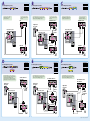
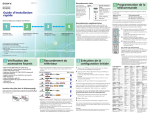
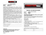
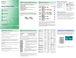
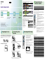
• Review the following chart to determine which diagram to use to connect the equipments in your system: 2-687-041-11 (1) For these equipments TAV-L1 See reverse side A B C D E Quick Setup Guide or Please follow the steps to setup your system: 1 Preparing for Use 2 3 Connecting Your System Running Initial Setup (See reverse side) 4 Programming the Remote Control F or 4 Programming the Remote Control The remote control is preset to operate Sony brand video equipment. Sony Equipment Cable Satellite receiver Follow the steps below to program your system’s remote control to operate the other video equipment. Using the code list below, find the three-digit code number for the manufacturer of your equipment. (If more than one code number is listed, use the number listed first.) 1 1 • See the “Cords Required” chart that appears with the diagram to determine which cords you’ll need. You may need to purchase extra accessories, such as cords, depending on the equipments you plan to connect. • Turn off and unplug all equipments before making connections. 2 3 Making Video Connections Your system includes several types of video inputs. Use the inputs that are available on your equipments that provide the best video performance, as shown in the table on the right. If your product is not working properly DO NOT RETURN TO THE STORE. For service and technical assistance Call our Customer Information Service Center (Toll Free): 1-800-222-SONY (7669) for US residents. 1-877-899-SONY (7669) for Canadian residents. Best Video Performance Inserting Batteries into the Remote Control 2 Connecting Your System 1 Remove the covers. Connector type HDMI* (High-Definition Multimedia Interface) Insert two size AA batteries (supplied) by matching the and on the batteries to the diagram inside the remote control’s battery compartment. 5 Attaching the frame grille 2 3 See reverse side to connect this system and other equipment. Connecting the FM wire antenna. VIDEO Aim your system’s remote control at the equipment, and press POWER. If the equipment responds, the programming is completed. If not, try the next code listed. S VIDEO Composite video * Support 480i, 480p, 720p, 1080i Tips • If no code is input within the above specified time, or an invalid or incorrect code number is input, the remote control automatically goes back to the previous setting. • In some cases, you may not be able to program your remote control to operate other equipment. In such cases, use the equipment’s own remote control. • Dead batteries or removing the batteries may cause the programmable codes to be lost and revert back to factory settings. Reprogramming the codes may be necessary. DIGITAL IN DIGITAL OUT COAX Press POWER to turn on the system. The Initial Setup screen appears. Manufacturer’s Codes Press MONITOR to switch the remote FUNCTION to MONITOR. Manufacturer Code Sony 101 Hamlin/Regal 123, 123, 125, 126, 127 Jerrold/G.I./Motorola 102, 103, 104, 105, 106, 107, 108, 109, 117, 118, 119, 123, 133 Oak 128, 129, 130 Panasonic 111, 113, 120, 121, 122, 131 Pioneer 113, 116 RCA 132 Scientific Atlanta 110, 111, 112 Tocom/Philips 117, 118 Zenith 113, 114 Press / to select the monitor language displayed on the menu screens, then press (OK). Press DVD (FUNCTION) to switch the remote FUNCTION to DVD. Press DVD (direct input select) to switch the input to DVD. Press (ENTER) without inserting a disc. The Setup Display for selecting the DVD language used in the on-screen display appears. LANGUAGE SETUP OSD: MENU: AUDIO: SUBTITLE: DVD FM ANTENNA OPT 3 6 7 FM wire antenna Bundle the connected cords, then replace the covers. Note Depending on the connected equipment cords, the back covers may not attach properly. In this case, try other cords, or use the system without the back covers. , then Cable Boxes Satellite Receivers ENGLISH ENGLISH FRENCH SPANISH PORTUGUESE 75 COAXIAL To set, press 4 Enter the three-digit manufacturer’s code number using the number buttons while the button is lit, approximately 30 seconds. To check if the code works 3 Running Initial Setup 1 2 4 Press and hold CABLE or SAT (FUNCTION) you want to program and press POWER simultaneously. The selected FUNCTION button will flash. Press ENT. When the programming is correct, the selected FUNCTION button will flash twice slowly, and when not, flashes five times quickly. Sony Corporation © 2006 Printed in Japan 1 Preparing for Use Programmable Code Number 101 (DVR) 201 (DSS) . Press / to select the language, then press (ENTER). The system displays the on-screen display, the menu and subtitles in the selected language. Manufacturer Code Sony 201 Hitachi 205 General Electric 202 Hughes 204 JVC/Dish Network/Echostar 210 Mitsubishi 209 Panasonic 203 Philips 211 RCA/PROSCAN 202, 208 Samsung 212 Toshiba 206, 207 A Cords Required RF Video S video Audio Use this diagram if you have; If your cable box has an HDMI jack, use that instead of the video connections shown here. 1 1 1 2 B Cords Required RF Video S video HDMI Audio Use this diagram if you have; The DVI-HDTV VIDEO connector does not provide audio, so audio cables must be connected to provide sound when a DVI to HDMI adaptor is used. If you are not using a cable box, connect your cable to the VCR’s RF IN jack. If you are not using a cable box, connect your cable to the VCR’s RF IN jack. VCR C Use this diagram if you have; Digital Recorder OUT IN Right side of the system IN 5 Rear of the system PC AUDIO IN AUDIO IN VIDEO R Rear of the system Satellite antenna Rear of the system L S VIDEO PC AUDIO IN S VIDEO VCR PC AUDIO IN VIDEO (MONO) VIDEO 3 3 OUT AUDIO R IN LINE OUT 1 (MONO) L (MONO) L LINE IN S VIDEO AUDIO R VIDEO IN If you are not using a cable box, connect your cable to the digital recorder’s RF IN jack. If your cable box or digital recorder has an HDMI jack, use that instead of the video connections shown here. SAT IN IN L Cords Required RF 3 S video 2 Audio 2 Satellite Receiver* OUT 1 3 2 1 1 3 AUDIO VIDEO VIDEO IN 3 3 AUDIO R 1 VIDEO DIGITAL IN VIDEO IN 3 3 DVD DIGITAL OUT VIDEO DIGITAL IN FM ANTENNA OPT VIDEO 75 COAXIAL COAX DIGITAL IN Cable Box DVD DIGITAL OUT FM ANTENNA OPT Cable Box Cable D Cords Required RF Video HDMI Audio Use this diagram if you have; or The DVI-HDTV VIDEO connector does not provide audio, so audio cables must be connected to provide sound when a DVI to HDMI adaptor is used. If your satellite receiver or cable box has a DVI jack, use that instead of the video connections shown here. Satellite Receiver*/ Cable Box IN IN 2 2 1 2 E Rear of the system OUT OUT IN IN Cords Required RF Video S video HDMI Audio Optical Coaxial Use this diagram if you have; The DVI-HDTV VIDEO connector does not provide audio, so audio cables must be connected to provide sound when a DVI to HDMI adaptor is used. Cable 3 2 1 1 2 1 1 F Cords Required RF Video HDMI Audio Optical Coaxial Use this diagram if you have; or DIGITAL OUT IN Right side of the system DIGITAL OUT OUT COAXIAL IN L HD Satellite Receiver*/ HD Cable Box OUT COAXIAL Satellite antenna Rear of the system IN Right side of the system IN 5 Satellite antenna or cable AUDIO IN AUDIO IN PC AUDIO IN R L PC AUDIO IN R S VIDEO S VIDEO VIDEO VIDEO (MONO) L 3 1 PC AUDIO IN R IN AUDIO VIDEO IN Rear of the system OUT LINE IN R VIDEO IN L AUDIO IN LINE OUT AUDIO R 1 VCR (MONO) AUDIO 2 2 1 2 1 1 The DVI-HDTV VIDEO connector does not provide audio, so audio cables must be connected to provide sound when a DVI to HDMI adaptor is used. HD Satellite Receiver* 5 Satellite antenna Cable Box Cable OUT Right side of the system 75 COAXIAL COAX IN L FM ANTENNA 75 COAXIAL COAX OUT 5 DVD DIGITAL OUT OPT S VIDEO VIDEO VIDEO 3 L (MONO) AUDIO R 1 VIDEO DIGITAL IN DVD DIGITAL OUT FM ANTENNA OPT COAX 75 COAXIAL VIDEO VCR DIGITAL IN DVD DIGITAL OUT VIDEO IN VCR 3 3 FM ANTENNA LINE IN OPT LINE IN OUT IN LINE OUT AUDIO COAX 75 COAXIAL HD Cable Box DIGITAL IN DIGITAL OUT FM ANTENNA IN AUDIO VIDEO OUT IN Cable OUT LINE OUT DVD OPT DIGITAL OUT OPTICAL VIDEO VIDEO Cable COAX 75 COAXIAL Cable * Satelite Antenna Cable not shown.