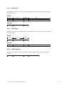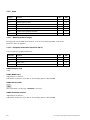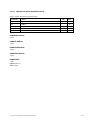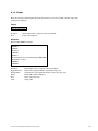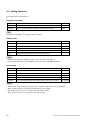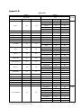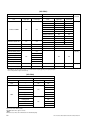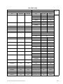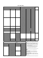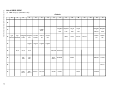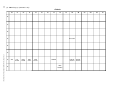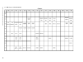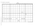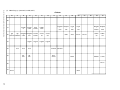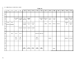
1
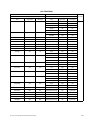
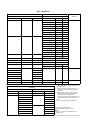
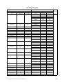
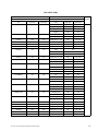
DATA PROJECTOR VPL-CX75 VPL-CX76 VPL-CX85 VPL-CX86 VPL-FX51 VPL-FX52 VPL-FX52L VPL-PX35 VPL-PX40 VPL-PX41 PROTOCOL MANUAL 1st Edition (Revised 7) ! WARNING This manual is intended for qualified service personnel only. To reduce the risk of electric shock, fire or injury, do not perform any servicing other than that contained in the operating instructions unless you are qualified to do so. Refer all servicing to qualified service personnel. ! WARNUNG Die Anleitung ist nur für qualifiziertes Fachpersonal bestimmt. Alle Wartungsarbeiten dürfen nur von qualifiziertem Fachpersonal ausgeführt werden. Um die Gefahr eines elektrischen Schlages, Feuergefahr und Verletzungen zu vermeiden, sind bei Wartungsarbeiten strikt die Angaben in der Anleitung zu befolgen. Andere als die angegeben Wartungsarbeiten dürfen nur von Personen ausgeführt werden, die eine spezielle Befähigung dazu besitzen. ! AVERTISSEMENT Ce manual est destiné uniquement aux personnes compétentes en charge de l’entretien. Afin de réduire les risques de décharge électrique, d’incendie ou de blessure n’effectuer que les réparations indiquées dans le mode d’emploi à moins d’être qualifié pour en effectuer d’autres. Pour toute réparation faire appel à une personne compétente uniquement. VPL-CX75/CX76/CX85/CX86/FX51/FX52/FX52L/PX35/PX40/PX41 Table of Contents 1. Introduction 2. RS-232C (VPL-CX75 and VPL-CX76 are excluded.) Appendix A. Setup Method For VPL-PX35 and PX40 A-1. Command ......................................................................... 18 A-1-1. Setting ..................................................................... 18 A-1-2. 2-1. Communication Specifications .......................................... 1 2-2. Command Block Format .................................................... 2 2-3. Block Format ..................................................................... 3 2-4. Connection ......................................................................... 4 Display ................................................................... 19 A-2. Setting Command ............................................................ 20 Appendix B 2-5. Communication Procedure ................................................ 4 2-5-1. Outline of Communication ....................................... 4 2-6. Communication Rules ....................................................... 5 2-7. Approximate Return Waiting Times ................................. 5 3. NETWORK 3-1. Introduction ........................................................................ 6 3-1-1. Advertisement .......................................................... 6 3-1-1-1. Function ................................................................. 6 3-1-1-2. Setup Items ............................................................ 6 3-1-2. Remote Control ........................................................ 7 3-1-2-1. 3-1-2-2. 3-2. Function ................................................................. 7 Setup Items ............................................................ 7 SDAP Protocol ................................................................... 8 3-3. SDCP Protocol ................................................................... 9 3-3-1. Format ...................................................................... 9 3-3-1-1. 3-3-1-2. Header ................................................................... 9 Community ............................................................ 9 3-3-1-3. 3-3-1-4. Command ............................................................ 10 SET Request ........................................................ 11 3-3-1-5. 3-3-1-6. GET Request ....................................................... 11 ERROR Response ............................................... 11 3-3-2. Items ....................................................................... 12 3-3-2-1. Model Dependent Category ................................ 12 3-3-2-2. 3-3-2-3. Equipment Information Acquisition (80**h) ...... 12 Network Information Acquisition (90**h) ......... 13 3-3-3. Error Code .............................................................. 14 3-3-3-1. Item Error ............................................................ 15 3-3-3-2. 3-3-3-3. Community Error ................................................ 15 Request Error ...................................................... 16 3-3-3-4. 3-3-3-5. Network Error ..................................................... 16 Comm Error ........................................................ 17 3-3-3-6. NVRAM Error .................................................... 17 VPL-CX75/CX76/CX85/CX86/FX51/FX52/FX52L/PX35/PX40/PX41 1 1. Introduction This protocol manual describes the basic configuration and basic operations of various commands used for projector. Projector can be controlled using the commands provided in “Appendix”. Using an external CONTROLLER , etc., inputs can be switched and the power can also be turned on and off. In the following paragraphs, “CONTROLLER” means an external device such as a PC which controls projector using these commands. 2. RS-232C (VPL-CX75 and VPL-CX76 are excluded.) 2-1. Communication Specifications <RS-232C Communication Signal> . . . . Full duplex communication channels (Flow control not performed.) Start-stop synchronism system Baud rate: 38.4 kbps (bits per second) The bit configuration is defined as follows. 1 START Bit + 8 DATA Bits + 1 PARITY Bit + 1 STOP Bit START D0 BIT (LSB) D1 D2 D3 D4 D5 D6 D7 PARITY STOP (MSB) (EVEN) BIT EVEN Parity.....Total number of “1”s from D0 to D7 is an even number. VPL-CX75/CX76/CX85/CX86/FX51/FX52/FX52L/PX35/PX40/PX41 1 2-2. Command Block Format The code from B0 to B7 as described below are transmitted. Transmission from the Master side Reception in the Master side B0 B1 B2 B3 B4 B5 Reception in the Master side (With Data) START CODE : 0 x A9 ITEM NUMBER ACK / NAK ITEM NUMBER SET / GET ACK REPLY DATA DUMMY DATA DATA B6 CHECK SUM B7 END CODE : 0 x 9A B0 START CORD Common in the all FORMAT B6 CHECK SUM B1 to B5 are calculated by OR; <Example of Calculation> 0 x A9 1010 0 x A9 1010 Answer 1010 1001 1001 1001 0 x A9 0 x A9 0 x 9A Answer 1010 1001 1011 1001 1010 1011 0 x BB B7 END CODE Common in the all FORMAT 2 VPL-CX75/CX76/CX85/CX86/FX51/FX52/FX52L/PX35/PX40/PX41 2-3. Block Format Transmission from the Master side B0 B1 B2 B3 B4 B5 START CODE ITEM NUMBER SET / GET DATA B6 CHECK SUM B7 END CODE Reception in the Master side B0 B1 B2 B3 B4 B5 ACK DUMMY DATA Reception in the Master side (With Data) B4 B5 SET: Data to be set (Refer to the Appendix B Table 2) GET: Unused. Set Dummy data [0 x 00, 0 x 00] Check Sum End of Command Receive results of the data transmission from the Projector. Results correspond with the data transmission Refer to the Appendix B Table 3 for the data in detail. END CODE B3 SET: 0 x 00 (Set data) GET: 0 x 01 (Get data) ACK / NAK CHECK SUM B2 Set the Data Category Value desired. Refer to the Appendix B Table 1 for details. Start of Command B7 B1 Start of Command START CODE B6 B0 Data transmission to the Projector START CODE ITEM NUMBER REPLY DATA B6 CHECK SUM B7 END CODE VPL-CX75/CX76/CX85/CX86/FX51/FX52/FX52L/PX35/PX40/PX41 [0 x 03] Express Reply data either of ACK, or NAK This data does not mean any senses. Dummy Data [0 x 00, 0 x 00] is stored. Check Sum End of Command Receive data from the Projector Start of Command Data to acquire Refer to the Appendix B Table 1 in detail. [0 x 02] Express data to be Reply data Received data Refer to the Appendix B Table 2 in detail. Check Sum End of Command 3 2-4. Connection <RS-232C Connection> Communication is enabled by the use of a D-Sub 9 Pin cross (reverse) cable. The pin assignment of D-Sub 9 Pin and D-Sub 25 Pin is as follows. D-Sub 9 Pin Shell = FG 3 2 7 8 6 5 1 4 9 D-Sub 25 Pin 1 2 3 4 5 6 7 8 20 22 FG TxD RxD RTS CTS DSR SG DCD DTR RI Name Grounding for safety protection or cable shield Transmission data Reception data Transmission request Transmission permission Data set ready GND for signal Data channel signal carrier detection Data terminal ready Calling display (Presence/absence of calling signal) Pins indicated as D-Sub 25 Pin are not used. Assured cable length: 15 m (However, assurance may not be applicable for some cables.) The software for controlling the projector from a PC is intended for performing transmission and reception for only the TxD and RxD lines. Therefore there is no handshake normally performed by RS-232C. 2-5. Communication Procedure 2-5-1. Outline of Communication All communication between CONTROLLER (PC, etc.) and DEVICE (PROJECTOR) is performed by the command block format. Communication is started by the issue of a command at CONTROLLER and ended when the return Data is sent to CONTROLLER after DEVICE receives the command. CONTROLLER is prohibited from sending several commands at one time. This means that after CONTROLLER sends one command, it cannot send other commands until DEVICE returns the return Data. DEVICE sends the return Data after processing the command. The time from when CONTROLLER sends the command until the return Data is returned differs according to the contents of the command. n When Sircs Direct Command is sent, return Data may not be returned in some cases. 4 VPL-CX75/CX76/CX85/CX86/FX51/FX52/FX52L/PX35/PX40/PX41 2-6. Communication Rules . When sending a command from CONTROLLER, the return Data from PROJECTOR should be received first before sending the next command. Even if the next command is sent before receiving the return Data, since PROJECTOR will not be able to receive that command, it does not return a response to CONTROLLER. Consequently, no error code is also sent. The following lists the approximate waiting times for PROJECTOR to return the return Data after CONTROLLER sends the command. . When a communication error occurs, PROJECTOR ignores the Data received until now, and set into the reception standby state. . For undefined commands or commends determined as invalid by PROJECTOR, PROJECTOR will send the “NAK” return Data to CONTROLLER . . Take note that when Data is written when the input signal of PROJECTOR is unstable, that Data (value) will not be incorporated. . When INDEX specified SIRCS direct command is transmitted, leave an interval of 45 msec until the next transmission. (Do not return the return Data (ACK, NAK) when the SIRCS direct command is received.) 2-7. Approximate Return Waiting Times The await-return time is approx. 30 msec. n This is the case, unless the communications are interfered anyway. VPL-CX75/CX76/CX85/CX86/FX51/FX52/FX52L/PX35/PX40/PX41 5 3. NETWORK 3-1. Introduction This section describes the specifications, performance and operations of the network service that is going to be installed in the target projector. 3-1-1. Advertisement The advertisement service is provided to facilitate development of a PC application that can automatically detect a projector on the network. This function is achieved by broadcasting the equipment information periodically to the network. 3-1-1-1. Function The equipment information shown below is transmitted as the broadcast packet periodically (at certain intervals). Information Description Category Category of the equipment Equipment name Name of the equipment Serial number Serial number of the equipment Installation information Installation location of the equipment Community Community name of the equipment Power status Power status of the equipment m . The category of projector is 0x0a. . The power status sets ffffh if communication error occurs. Protocol The SDAP protocol is defined in order to provide this service. Item Description Protocol name SDAP (Simple Display Advertisement Protocol) Transport UDP Port number 53862 BC interval Once every 30 seconds (initial value) 3-1-1-2. Setup Items The items that can be set for the advertisement service are described below. 6 Setup items Description Port Port number Interval Broadcast interval VPL-CX75/CX76/CX85/CX86/FX51/FX52/FX52L/PX35/PX40/PX41 3-1-2. Remote Control The remote control service is provided that can control the target equipment from remote location via network. The SDCP protocol that serves to acquire the basic information such as equipment name and serial numbers is installed in this projector. 3-1-2-1. Function This responds to the control command and requests for acquiring the status and information supplied from clients. Control request Enables the input to be selected and picture control to be adjusted. SIRCS request Enables remote control by sending the SIRCS code. Status request Enables equipment status information such as power status, error information and power-on time to be acquired. Information request Enables equipment information such as equipment name, serial number and installation information to be acquired. Protocol Item Description Protocol name SDCP (Simple Display Control Protocol) Transport TCP Port number 53484 TCP connection timeout 30 seconds 3-1-2-2. Setup Items The items that can be set for the remote control service are described below. Setup item Description Port Port number Timeout TCP connection timeout time VPL-CX75/CX76/CX85/CX86/FX51/FX52/FX52L/PX35/PX40/PX41 7 3-2. SDAP Protocol This section describes the SDAP packet structure. Header (4) Community (4) Serial No. Power Status (4) (2) Product name (12) Location (24) Fig.1 Packet structure 1) Header The header consists of ID (16 bit), version (8 bit) and category (8 bits). 0 0 1 2 3 1 4 5 6 7 8 9 0 1 2 2 3 4 5 6 7 “DA” (16) 8 9 0 (Bit position) 3 1 2 3 4 5 Version (8) 6 7 8 9 0 1 Category (8) Fig. 2 Header ID It is fixed to “DA”. Version This indicates the version number of protocol. It is fixed to 01h (version 1). Category Category number 0x0a of the projector is entered here. 2) Community The community that is set in the display equipment is entered. Community consists of four alphanumeric characters (case sensitive). The display equipment has the default value “SONY” when shipped from the factory. 0 0 1 2 3 1 4 5 6 7 8 9 0 1 2 2 3 4 5 6 7 8 9 0 (Bit position) 3 1 2 3 4 5 6 7 8 9 0 1 Community (32) Fig. 3 Community 3) Equipment Information Product Name Name of equipment (Maximum twelve characters) In case, less than twelve characters, 00h is entered in the blank space. Serial No. Serial number is entered. Power Status. Power supply status of the equipment is entered. Location Information of installation location (Maximum twenty four characters) In case, less than twenty four characters, 00h is entered in the blank space. 8 VPL-CX75/CX76/CX85/CX86/FX51/FX52/FX52L/PX35/PX40/PX41 3-3. SDCP Protocol This section describes the packet structure of SDCP. Header (2) Community (4) Command (4) Data (n) Fig. 1 Packet structure 3-3-1. Format 3-3-1-1. Header The header consists of Version (8 bits) and Category (8 bits). 0 0 1 2 3 (Bit position) 1 4 5 6 7 8 9 Version (8) 0 1 2 3 4 5 Category (8) Fig. 2 Header structure Version This indicates the version number of protocol. It is fixed to 02h (version 2). Category Category number 0x0a of the projector is entered here. Projector checks the category number. If a different category number is entered, the request is ignored. 3-3-1-2. Community When the community Data matches the community that is set in the display equipment, the request is executed. Community consists of four alphanumeric characters (case sensitive). All display equipment has the default value “SONY” when shipped from the factory. 0 0 1 2 3 1 4 5 6 7 8 9 0 1 2 2 3 4 5 6 7 8 9 0 (Bit position) 3 1 2 3 4 5 6 7 8 9 0 1 Community (32) n Community should be entered with four characters. Three characters or less are not accepted. VPL-CX75/CX76/CX85/CX86/FX51/FX52/FX52L/PX35/PX40/PX41 9 3-3-1-3. Command This section describes the format of the request command and the response command. 0 0 1 2 3 1 4 5 6 7 8 9 0 1 2 2 Request/Response (8) 3 4 5 6 7 8 9 0 (Bit position) 3 1 Item No (16) 2 3 4 5 6 7 8 9 0 1 Data Length (8) (1) Request This section describes the format of the request command that is issued from the host PC to the projector. Community This is the same alphanumeric characters as those of community that is set in the projector to which request is going to be sent. Request There are only two types of request. One is the GET request to acquire the projector information and status. The other is the SET request to modify the projector setup. Request Contents SET (00h) Used to control turning the power on/off and to control the input selector, and to change the various setups. SET (01h) Used to acquire the installation information, equipment status and various setup values. Item No. This is the item number of the request target. Data Length This is the length of the Data accompanying the request. The maximum length is 128 bytes. If there is no Data, it is 0. Data This is the Data accompanying the request. (2) Response This section describes the format of the response command which is used to return a response to the host PC from the projector. Community The same alphanumeric characters as those of the request is entered. Response The response returns the result of executing the request from the host PC. Response Contents NG (00h) Indicates that the request is illegal or cannot be executed. OK (01h) Indicates that the request was executed correctly. Item No. The same value as those of the request is entered. Data Length This is the length of the Data accompanying the response. The maximum length is 128 bytes. If there is no Data, it is 0. Data This is the Data accompanying the response. 10 VPL-CX75/CX76/CX85/CX86/FX51/FX52/FX52L/PX35/PX40/PX41 3-3-1-4. SET Request The SET request is used to set a new value in the specified item. Details of the request and the response are described below. Request Request Item No. Data Length 00h Item No. n Item No. 0 Data Set Data (n byte) Response OK (01h) 3-3-1-5. GET Request The GET request is used to acquire the value of the specified item. Details of the request and the response are described below. Request Request Item No. Data Length 01h Item No. 0 Item No. n Response OK (01h) Get Data (n byte) 3-3-1-6. ERROR Response When an error occurs in the contents of a request or in the result of execution, NG is returned as the response. NG (00h) Item No. 2 VPL-CX75/CX76/CX85/CX86/FX51/FX52/FX52L/PX35/PX40/PX41 Error Code (16) 11 3-3-2. Items Category Contents SET GET 00**h Used to control and to change the various setups. O O 01**h Used to acquire the status. 03**h Used to reset memory. O 17**h Sircs (15 bit category) O 19**h Sircs (20 bit category) O 80**h Used to acquire equipment information. O 90**h Used to acquire network setup information. O O 3-3-2-1. Model Dependent Category The supported contents of 00**h, 01**h, 03**h, 17**h and 19**h change depending on the model. Details are shown on Appendix. 3-3-2-2. Equipment Information Acquisition (80**h) Used to acquire the equipment information. Lower byte Contents SET 00h Category Code O 01h Model name O 02h Serial number O 03h Installation location O GET O 0x8000 Category code 1 byte 0x8001 Model name Alphanumeric 12 characters If the number of characters is less than 12, the remaining digits are filled with 00h. 0x8002 Serial number 4 bytes n The serial number is in the range of 00000000 to 99999999. 0x8003 Installation location Alphanumeric 24 characters If the number of characters is less than 24, the remaining digits are filled with 00h. 12 VPL-CX75/CX76/CX85/CX86/FX51/FX52/FX52L/PX35/PX40/PX41 3-3-2-3. Network Information Acquisition (90**h) Used to acquire the network setup information. Lower bytes Contents SET GET 00h MAC Address O 01h IP Address O 02h Subnet Mask O 03h Default Gateway O 04h DHCP O 0x9000 Mac Address 6 bytes 0x9001 IP Address 4 bytes 0x9002 Subnet Mask 4 bytes 0x9003 Default Mask 4 bytes 0x9004 DHCP 1 byte DHCP invalid : 0 DHCP valid : 1 VPL-CX75/CX76/CX85/CX86/FX51/FX52/FX52L/PX35/PX40/PX41 13 3-3-3. Error Code The error code list is shown below with a detailed description of each. Category Error Error Code Item Error (01**h) Invalid Item 01h Invalid Item Request 02h Invalid Length 03h Invalid Data 04h Short Data 11h Not Applicable Item 80h Community Error (02**h) Different Community 01h Request Error (10**h) Invalid Version 01h Invalid Category 02h Invalid Request 03h Short Header 11h Short Community 12h Short Command 13h Network Error (20**h) Timeout 01h Comm Error (F0**h) Timeout 01h Check Sum Error 10h NVRAM Error (F1**h) 14 Framing Error 20h Parity Error 30h Over Run Error 40h Other Comm Error 50h Unknown Response F0h Read Error 10h Write Error 20h VPL-CX75/CX76/CX85/CX86/FX51/FX52/FX52L/PX35/PX40/PX41 3-3-3-1. Item Error This error occurs when the Item No. of a request is illegal or its Data is illegal. The conditions for occurrence of the respective errors are shown below. Invalid Item An unsupported Item No. is specified. Example 1: The unsupported category 0xA** is specified. Example 2: The unsupported Item No. 0x8010 is specified. Invalid Item Request The Item No. is supported but an unsupported Request is issued. Example: An attempt is made to set Data in the Model Name (0x8001). Invalid Length Data Length of the specified Item No. is too long. Example: An attempt is made to set 25 byte Data in the installation location (0x8003). Invalid Data Data of the specified Item No. is outside the setting range. Example: An attempt is made to set 101 in the Item when the setting range of the Item is 1 to 100. Short Data The length of Data is shorter than the value specified by the Data Length. Example: The actual Data length is 9 bytes but Data Length is 10. Not Applicable Item An item that is not valid at present is specified. Example: The item to switch the display is specified when the main power is off. 3-3-3-2. Community Error This error occurs when community is different. Example: “ABCD” is specified when “SONY” is set. VPL-CX75/CX76/CX85/CX86/FX51/FX52/FX52L/PX35/PX40/PX41 15 3-3-3-3. Request Error This error occurs when Header or Command is illegal. The conditions of occurrence of the respective errors are shown below. Invalid Version The version of the Header is other than 2. n When another version is supported, an error occurs in all versions other than the supported version. Invalid Category The category does not match. Example: 0x0B is specified in the device of Category = 0x0A. Invalid Request An unsupported request is specified. Example: Request = 0x02 is specified. Short Header The received Data is 1 byte. Short Community The received Data is in the range of 2 to 5 bytes. Short Command The received Data is in the range of 6 to 9 bytes. 3-3-3-4. Network Error This is an error that occurs in TCP/IP. The conditions of occurrence of the respective errors are shown below. Timeout Communication was interrupted. 16 VPL-CX75/CX76/CX85/CX86/FX51/FX52/FX52L/PX35/PX40/PX41 3-3-3-5. Comm Error This is an error in communication with the main control microprocessor of the display. Timeout Reception Data is not returned after Data is sent. Check Sum Error A check sum error occurred in the main control microprocessor of the display. Framing Error A framing error occurred. Parity Error A parity error occurred. Over Run Error An overrun error occurred. Other Comm Error Another error occurred. Unknown Response The Data cannot be processed was received. 3-3-3-6. NVRAM Error Read Error Reading from NVRAM was failed. Write Error Writing to NVRAM was failed. VPL-CX75/CX76/CX85/CX86/FX51/FX52/FX52L/PX35/PX40/PX41 17 Appendix A. Setup Method For VPL-PX35 and PX40 Establishing the network setup such as IP address can be implemented from the PC browser, and the information such as installation location can be viewed on the PC browser. A-1. Command A-1-1. Setting Enter the following command using the format shown below in a browser as URL, and then the simple response is returned. Format http://IP address/Item?Value IP address Item Value The IP address that is assigned to the network block Name of the setup item Setting value Response The following HTML is returned that enables to confirm OK or NG simply. <HTML> <TITLE> IP address </TITLE> <BODY> < Equipment name: Serial number><BR><BR> Result [Item = Value] </BODY> </HTML> IP address Equipment name Serial number Result Item Value 18 The IP address that is assigned to the network block Name of the equipment in which setup is implemented Serial number of the equipment in which setup is implemented Result (OK or NG) is displayed. Name of the setup item Setting value VPL-CX75/CX76/CX85/CX86/FX51/FX52/FX52L/PX35/PX40/PX41 A-1-2. Display Enter the following command using the format shown below in a browser as URL, and then value of the setting item is displayed. Format http://IP address/Item IP address Item The IP address that is assigned to the network block Name of the setup item Response The following HTML is returned. <HTML> <TITLE> IP address </TITLE> <BODY> < Equipment name: Serial number><BR><BR> Result [Item = Value] </BODY> </HTML> IP address Equipment name Serial number Result Item Value The IP address that is assigned to the network block Name of the equipment that has acquired the setup value Serial number of the equipment that has acquired the setup value Result (OK or NG) is displayed. Name of the setup item Setting value VPL-CX75/CX76/CX85/CX86/FX51/FX52/FX52L/PX35/PX40/PX41 19 A-2. Setting Command Each setting item is described below. Equipment information Item Description Default location Sets location of the equipment installation. (Maximum 24 alphanumeric characters) _ Community Sets the equipment community. (Maximum 4 alphanumeric characters) SONY n Location and community do not support Japanese character. Network setup Item Description Default dhcp Specifies method of setting IP address. No ipaddr IP address 192.168.0.1 subnet Subnet mask 255.255.0.0 gateway Default gateway 0.0.0.0 restart Restarts the network block to make the network setup effective. m . When the network setup is changed, execute restart to make the setup effective. . For the setup of dhcp, set 1 to make DHCP effective and set 0 to make DHCP ineffective. Service setup Item Description Default ad_port Port number of the Advertisement service 53862 ad_interval Broadcast interval of the Advertisement service (in units of second) 30 (seconds) ad_ip IP address of the Advertisement service 0.0.0.0 rc_port Port number of the Remote Control service 53484 rc_timeout TCP connection timeout time of the Remote Control service (in units of second) 30 (seconds) m . When network setup is changed, executing restart is required to make the network setup effective. . When ad_Interval value is set to 0, the advertisement service is stopped. . The ad_Interval can be set to 0 or a value in the range of 10 to 65535. . The rc_timeout can be set to a value in the range of 0 to 65535. 20 VPL-CX75/CX76/CX85/CX86/FX51/FX52/FX52L/PX35/PX40/PX41 Appendix B (VPL-FX51) <Table 1> <Table 2> Item Number Item INPUT Upper byte 00h Data Lower byte 01h Remarks Data Upper byte Lower byte VIDEO 00h 00h S VIDEO 00h 01h INPUT A 00h 02h INPUT B 00h 03h INPUT C 00h 04h CONTRAST 00h 10h Setting value (0 to 100) 00h 00h to 64h BRIGHTNESS 00h 11h Setting value (0 to 100) 00h 00h to 64h COLOR 00h 12h Setting value (0 to 100) 00h 00h to 64h HUE 00h 13h Setting value (0 to 100) 00h 00h to 64h SHARPNESS 00h 14h Setting value (0 to 100) 00h 00h to 64h RGB ENHANCER 00h 15h Setting value (0 to 100) 00h 00h to 64h LOW 00h 00h HIGH 00h 01h COL TEMP DDE ASPECT SCAN CONV PICTURE MUTING INPUT A 00h 00h 00h 00h 00h 00h 17h 18h 20h 21h 30h 32h OFF 00h 00h PROGRESSIVE 00h 01h FILM 00h 02h 16 : 9 00h 00h 4:3 00h 01h OFF 00h 00h ON 00h 01h OFF 00h 00h ON 00h 01h COMPUTER 00h 00h COMPONENT 00h 01h VIDEO GBR 00h 02h HIGH 00h 00h LAMP MODE 00h 40h STANDARD 00h 01h GAIN RED 00h 80h Setting value (0 to 255) 00h 00h to FFh GAIN GREEN 00h 81h Setting value (0 to 255) 00h 00h to FFh GAIN BLUE 00h 82h Setting value (0 to 255) 00h 00h to FFh BIAS RED 00h 83h Setting value (0 to 255) 00h 00h to FFh BIAS GREEN 00h 84h Setting value (0 to 255) 00h 00h to FFh BIAS BLUE 00h 85h Setting value (0 to 255) 00h 00h to FFh NO ERROR 00h 00h STATUS ERROR 01h VPL-CX75/CX76/CX85/CX86/FX51/FX52/FX52L/PX35/PX40/PX41 01h LAMP ERROR 00h 01h FAN ERROR 00h 02h COVER ERROR 00h 04h TEMP ERROR 00h 08h D5V ERROR 00h 10h POWER ERROR 00h 20h WARNING ERROR 00h 40h Set/Get Get only 21 (VPL-FX51) <Table 1> <Table 2> Item Number Item Upper byte STATUS POWER Data Lower byte 01h CONTROL MODE SEL Remarks Data Upper byte Lower byte STANBY 00h 00h START UP 00h 01h STARTUP LAMP 00h 02h POWER ON 00h 03h COOLING1 00h 04h 02h COOLING2 00h 05h SAVING COOLING1 00h 06h SAVING COOLING2 00h 07h SAVING STABY 00h 08h USER 00h 00h SERVICE 00h 01h 05h LAMP TIMER 01h 13h USE TIME 0000h-ffffh*1 ROM VERSION 01h 1Dh MAIN ROM VERSION *2 SC ROM VERSION 01h 1Eh SC ROM VERSION *2 Channel Memory Reset 01h Status Memory Reset 02h Set Memory Reset 04h W/B Low Save 05h W/B High Save 06h 01h Set only 03h 03h W/B All Save Get only 00h 00h Sircs (15bit category) 17h Refer to table 4 _ 00h 00h Sircs (20bit category) 19h Refer to table 5 _ 00h 00h Set only*3 *1Example) In case the lamp timer indicates 1000H, return values are [03h] upper byte and [E8h] lower byte. *2Example) In case the software version is 1.03, return values are [01h] upper byte and [03h] lower byte. *3It is corresponded to single command only. (VPL-FX51) <Table 3> Item Number Item ACK Data Data Upper byte Lower byte _ 00h 00h Undefined Command 01h Size Error 04h Select Error NAK 01h 05h Range Over 06h Not Applicable 0Ah Check Sum Error 10h Framing Error 20h Parity Error F0h 30h Over Rub Error 40h Other Comm Error 50h Approximate Return Waiting Times The await-return time is approx. 50 msec. n This is the case, unless the communications are interfered anyway. 22 VPL-CX75/CX76/CX85/CX86/FX51/FX52/FX52L/PX35/PX40/PX41 (VPL-FX52/FX52L) <Table 1> <Table 2> Item Number Data Remarks Item Upper byte Lower byte Data Upper byte Lower byte Input 00h 01h Video 00h 00h S-Video 00h 01h Input-A 00h 02h Input-B 00h 03h Picture Mode 00h 02h Input-C 00h 04h Dynamic 00h 00h Standard 00h 01h Contrast 00h 10h Setting value (0-100) 00h 00h to 64h Brightness 00h 11h Setting value (0-100) 00h 00h to 64h Color 00h 12h Setting value (0-100) 00h 00h to 64h Hue 00h 13h Setting value (0-100) 00h 00h to 64h Sharpness 00h 14h Setting value (0-100) 00h 00h to 64h RGB Enhancer 00h 15h Setting value (0-100) 00h 00h to 64h ColTemp 00h 17h High 00h 00h Low 00h 01h Off 00h 00h Progressive 00h 01h Film 00h 02h Off 00h 00h On 00h 01h Off 00h 00h On 00h 01h DDE Wide Mode Scan Conv 00h 00h 00h 18h 20h 21h Picture Muting 00h 30h Off 00h 00h On 00h 01h Input-C Signal Sel 00h 32h Computer 00h 00h Component 00h 01h Video GBR 00h 02h Lamp Mode 00h 40h High 00h 00h Standard 00h 01h Gain Red 00h 80h Setting value (0-255) 00h 00h to FFh Gain Green 00h 81h Setting value (0-255) 00h 00h to FFh Gain Blue 00h 82h Setting value (0-255) 00h 00h to FFh Bias Red 00h 83h Setting value (0-255) 00h 00h to FFh Bias Green 00h 84h Setting value (0-255) 00h 00h to FFh Bias Blue 00h 85h Setting value (0-255) 00h 00h to FFh VPL-CX75/CX76/CX85/CX86/FX51/FX52/FX52L/PX35/PX40/PX41 Set/Get 23 (VPL-FX52/FX52L) <Table 1> <Table 2> Item Number Data Item Upper byte Lower byte Status Error 01h 01h Status Power 01h Control Mode Select Data 02h 01h Upper byte Remarks Lower byte No Error 00h 00h Lamp Error 00h 01h 02h Fan Error 00h Cover Error 00h 04h Temp Error 00h 08h D5V Error 00h 10h Power Error 00h 20h Warning Error 00h 40h Stanby 00h 00h 01h Start Up 00h Start Up Lamp 00h 02h Power On 00h 03h Cooling1 00h 04h Cooling2 00h 05h Saving Cooling1 00h 06h Saving Cooling2 00h 07h Saving Staby 00h 08h User Mode 00h 00h Service Mode 00h 01h 05h Lamp Timer 01h 13h Lamp Use Time 0000h-FFFFh*1 ROM Version 01h 1Dh MAIN ROM Version *2 SC ROM Version 01h 1Eh SC ROM Version *2 Status Security*3 01h 1Fh Disable Channel Memory Reset 03h 01h Status Memory Reset 00h Enable 00h 01h _ 00h 00h Set only 00h 00h Set only*4 00h 00h 02h Set Memory Reset 03h W/B All Save 04h W/B High Save 05h W/B Low Save 06h Sircs (15 bit category) 17h Refer to table 6 _ Sircs (20 bit category) 19h Refer to table 7 _ (VPL-FX52/FX52L) <Table 3> Item Number Data Item Data Upper byte Lower byte ACK _ 00h 00h NAK Undefined Command 01h 01h Size Error 04h Select Error 05h Range Over 06h Not Applicable 0Ah Check Sum Error 24 00h Get only F0h *1 Example) In case the lamp timer indicates 1000H, return values are [03h] upper byte and [E8h] lower byte. *2 Example) In case the software version is 1.03, return values are [01h] upper byte and [03h] lower byte. *3 While the set is security locked, after power switch is turned on, you can check that pass sword input screen is indicated or not. During pass word input screen indicating, return values are [00h] upper byte and [01h] lower byte. *4 It is corresponded to single command only. 10h Framing Error 20h Parity Error 30h Over Rub Error 40h Other Comm Error 50h Approximate Return Waiting Times The await-return time is approx. 50 msec. n This is the case, unless the communications are interfered anyway. VPL-CX75/CX76/CX85/CX86/FX51/FX52/FX52L/PX35/PX40/PX41 (VPL-PX35, PX40, PX41) <Table 1> <Table 2> Item Number Data Remarks Item Upper byte Lower byte Data Upper byte Lower byte Input 00h 01h Video 00h 00h S-Video 00h 01h Input-A 00h 02h Input-B 00h 03h Input-C 00h 04h Input-D 00h 05h Dynamic 00h 00h Standard 00h 01h Picture Mode 00h 02h Contrast 00h 10h Setting value (0-100) 00h 00h to 64h Brightness 00h 11h Setting value (0-100) 00h 00h to 64h Color 00h 12h Setting value (0-100) 00h 00h to 64h Hue 00h 13h Setting value (0-100) 00h 00h to 64h Sharpness 00h 14h Setting value (0-100) 00h 00h to 64h RGB Enhancer 00h 15h Setting value (0-100) 00h 00h to 64h Volume 00h 16h Setting value (0-100) 00h 00h to 64h ColTemp 00h 17h High 00h 00h Low 00h 01h Off 00h 00h DDE Wide Mode 00h 00h 18h 20h Progressive 00h 01h Film 00h 02h Off 00h 00h On 00h 01h Scan Conv 00h 21h Off 00h 00h On 00h 01h Picture Muting 00h 30h Off 00h 00h On 00h 01h Audio Muting 00h 31h Off 00h 00h On 00h 01h Input-D Signal Sel 00h 33h Computer 00h 00h Component 00h 01h Video GBR 00h 02h 00h Lamp Mode 00h 40h High 00h Standard 00h 01h GAIN RED 00h 80h Setting value (0-255) 00h 00h to FFh GAIN GREEN 00h 81h Setting value (0-255) 00h 00h to FFh GAIN BLUE 00h 82h Setting value (0-255) 00h 00h to FFh BIAS RED 00h 83h Setting value (0-255) 00h 00h to FFh BIAS GREEN 00h 84h Setting value (0-255) 00h 00h to FFh BIAS BLUE 00h 85h Setting value (0-255) 00h 00h to FFh VPL-CX75/CX76/CX85/CX86/FX51/FX52/FX52L/PX35/PX40/PX41 Set/Get 25 (VPL-PX35, PX40, PX41) <Table 1> <Table 2> Item Number Data Item Upper byte Lower byte STATUS ERROR 01h 01h STATUS POWER 01h CONTROL MODE SEL 01h Data Upper byte Remarks Lower byte NO ERROR 00h 00h LAMP ERROR 00h 01h 02h FAN ERROR 00h COVER ERROR 00h 04h TEMP ERROR 00h 08h D5V ERROR 00h 10h POWER ERROR 00h 20h WARNING ERROR 00h 40h STANBY 00h 00h 01h 02h START UP 00h STARTUP LAMP 00h 02h POWER ON 00h 03h COOLING1 00h 04h COOLING2 00h 05h SAVING COOLING1 00h 06h SAVING COOLING2 00h 07h SAVING STABY 00h 08h USER MODE 00h 00h SERVICE MODE 00h 01h 05h LAMP TIMER 01h 13h LAMP USE TIME 0000h-ffffh*1 ROM VERSION 01h 1Dh MAIN ROM VERSION *2 SC ROM VERSION 01h 1Eh SC ROM VERSION STATUS SECURITY*3 01h 1Fh Disable Channel Memory Reset 03h 01h Status Memory Reset *2 00h 00h Enable 00h 01h _ 00h 00h Set only Set only*4 02h Set Memory Reset 03h W/B All Save 04h W/B High Save 05h W/B Low Save 06h Sircs (15 bit category) 17h Refer to table 8 _ 00h 00h Sircs (20 bit category) 19h Refer to table 9 _ 00h 00h (VPL-PX35, PX40, PX41) <Table 3> Item Number Data Item Data Upper byte Lower byte ACK _ 00h 00h NAK Undefined Command 01h 01h Size Error 04h Select Error 05h Range Over 06h Not Applicable 0Ah Check Sum Error 26 Get only F0h *1 Example) In case the lamp timer indicates 1000H, return values are [03h] upper byte and [E8h] lower byte. *2 Example) In case the software version is 1.03, return values are [01h] upper byte and [03h] lower byte. *3 While the set is security locked, after power switch is turned on, you can check that pass sword input screen is indicated or not. During pass word input screen indicating, return values are [00h] upper byte and [01h] lower byte. *4 It is corresponded to single command only. 10h Framing Error 20h Parity Error 30h Over Rub Error 40h Other Comm Error 50h Approximate Return Waiting Times The await-return time is approx. 50 msec. n This is the case, unless the communications are interfered anyway. VPL-CX75/CX76/CX85/CX86/FX51/FX52/FX52L/PX35/PX40/PX41 (VPL-CX75, CX76) <Table 1> <Table 2> Item Number Data Remarks Item Upper byte Lower byte Data Upper byte Lower byte Input 00h 01h Video 00h 00h S-Video 00h 01h Input-A 00h 02h Input-B 00h 03h Dynamic 00h 00h Standard 00h 01h Picture Mode 00h 02h Contrast 00h 10h Setting value (0 - 100) 00h 00h - 64h Brightness 00h 11h Setting value (0 - 100) 00h 00h - 64h Color 00h 12h Setting value (0 - 100) 00h 00h - 64h Hue 00h 13h Setting value (0 - 100) 00h 00h - 64h Sharpness 00h 14h High 00h Middle 01h Low 02h Volume 00h 16h Setting value (0 - 100) 00h 00h - 64h ColTemp 00h 17h High 00h 00h Low 00h 01h Off 00h 00h On 00h 01h Off 00h 00h On 00h 01h Off 00h 00h On 00h 01h Off 00h 00h On 00h 01h Computer 00h 00h Compornent 00h 01h Wide Mode Scan Conv 00h 00h 20h 21h PictureMuting 00h 30h AudioMuting 00h 31h Input-A Signal Sel Input-B Select 00h 00h 32h 33h Video GBR 00h 02h Memory Stick 00h 03h Air Shot 00h 04h 00h 00h Lamp Mode 00h 40h High Standard 00h 01h Gain Red 00h 80h Setting value (0 - 255) 00h 00h - FFh Gain Green 00h 81h Setting value (0 - 255) 00h 00h - FFh Gain Blue 00h 82h Setting value (0 - 255) 00h 00h - FFh Bias Red 00h 83h Setting value (0 - 255) 00h 00h - FFh Bias Green 00h 84h Setting value (0 - 255) 00h 00h - FFh Bias Blue 00h 85h Setting value (0 - 255) 00h 00h - FFh VPL-CX75/CX76/CX85/CX86/FX51/FX52/FX52L/PX35/PX40/PX41 Set/Get 27 (VPL-CX75, CX76) <Table 1> <Table 2> Item Number Data Upper byte Lower byte Data Upper byte Lower byte Status Error 01h 01h No Error 00h 00h Status Power 01h Control Mode Select 01h Lamp Error 00h 01h Fan Error 00h 02h Cover Error 00h 04h Temp Error 00h 08h D5V Error 00h 10h POWER ERROR 00h 20h Warning Error 00h 40h 02h Stanby 00h 00h Start Up 00h 01h Start Up Lamp 00h 02h Power On 00h 03h Cooling1 00h 04h Cooling2 00h 05h Saving Cooling1 00h 06h Saving Cooling2 00h 07h Saving Stanby 00h 08h User Mode 00h 00h Service Mode 00h 01h 05h Get only Lamp Timer 01h 13h Lamp Use Time 0000h-FFFFh *1 ROM Version 01h 1Dh MAIN ROM Version *2 SC ROM Version 01h 1Eh SC ROM Version *2 Status Security 01h 1Fh Disable 00h 00h Enable 00h 01h _ 00h 00h Set only Set only*4 Channel Memory Reset 03h Status Memory Reset 01h 02h Set Memory Reset 03h W/B All Save 04h W/B Low Save 05h W/B High Save 06h Sircs(15bit category) 17h Refer to table 10 _ 00h 00h Sircs(20bit category) 19h Refer to table 11 _ 00h 00h (VPL-CX75, CX76) <Table 3> Item Number Data Item Data Upper byte Lower byte ACK _ 00h 00h NAK Undefined Command 01h 01h Size Error 04h Select Error 05h Range Over 06h Not Applicable Check Sum Error 28 Remarks Item *1 Example) In case the lamp timer indicates 1000H, return values are [03h] upper byte and [E8h] lower byte. *2 Example) In case the software version is 1.03, return values are [01h] upper byte and [03h] lower byte. *3 While the set is security locked, after power switch is turned on, you can check that pass sword input screen is indicated or not. During pass word input screen indicating, return values are [00h] upper byte and [01h] lower byte. *4 It is corresponded to single command only. 0Ah F0h 10h Framing Error 20h Parity Error 30h Over Rub Error 40h Other Comm Error 50h The await-return time of return value is approx. 50 msec. n This is the case, unless the communications are interfered anyway. VPL-CX75/CX76/CX85/CX86/FX51/FX52/FX52L/PX35/PX40/PX41 (VPL-CX85, CX86) <Table 1> <Table 2> Item Number Data Remarks Item Upper byte Lower byte Data Upper byte Lower byte Input 00h 01h Video 00h 00h S-Video 00h 01h Input-A 00h 02h Input-B 00h 03h Picture Mode 00h 02h Input-C 00h 04h Dynamic 00h 00h Standard 00h 01h Contrast 00h 10h Setting value (0-100) 00h 00h-64h Brightness 00h 11h Setting value (0-100) 00h 00h-64h Color 00h 12h Setting value (0-100) 00h 00h-64h Hue 00h 13h Setting value (0-100) 00h 00h-64h Sharpness 00h 14h High 00h Middle 01h Low 02h Volume 00h 16h Setting value (0-100) 00h 00h-64h ColTemp 00h 17h High 00h 00h Low 00h 01h 00h 00h Wide Mode 00h 20h Off On 00h 01h Scan Conv 00h 21h Off 00h 00h On 00h 01h Off 00h 00h On 00h 01h Off 00h 00h On 00h 01h Computer 00h 00h Compornent 00h 01h Picture Muting Audio Muting Input-A Signal Sel Input-C Select Lamp Mode 00h 00h 00h 00h 00h 30h 31h 32h 33h 40h Video GBR 00h 02h Memory Stick 00h 03h Air Shot 00h 04h High 00h 00h Standard 00h 01h Gain Red 00h 80h Setting value (0-255) 00h 00h-FFh Gain Green 00h 81h Setting value (0-255) 00h 00h-FFh Gain Blue 00h 82h Setting value (0-255) 00h 00h-FFh Bias Red 00h 83h Setting value (0-255) 00h 00h-FFh Bias Green 00h 84h Setting value (0-255) 00h 00h-FFh Bias Blue 00h 85h Setting value (0-255) 00h 00h-FFh VPL-CX75/CX76/CX85/CX86/FX51/FX52/FX52L/PX35/PX40/PX41 Set/Get 29 (VPL-CX85, CX86) <Table 1> <Table 2> Item Number Data Item Upper byte Lower byte Status Error 01h 01h Status Power 01h Control Mode Select 01h Data 02h Upper byte No Error 00h 00h Lamp Error 00h 01h 02h Fan Error 00h Cover Error 00h 04h Temp Error 00h 08h D5V Error 00h 10h Power Error 00h 20h Warning Error 00h 40h Stanby 00h 00h 01h Start Up 00h Startup Lamp 00h 02h Power On 00h 03h Cooling1 00h 04h Cooling2 00h 05h Saving Cooling1 00h 06h Saving Cooling2 00h 07h Saving Stanby 00h 08h User Mode 00h 00h Service Mode 00h 01h 05h Lamp Timer 01h 13h Lamp Use Time 0000h-FFFFh*1 ROM Version 01h 1dh MAIN ROM Version *2 SC ROM Version 01h 1eh SC ROM Version *2 Status Security*3 01h 1fh Disable 00h Channel Memory Reset 03h 01h Status Memory Reset Remarks Lower byte 00h Enable 00h 01h _ 00h 00h Set only Set only*4 02h Set Memory Reset 03h W/B All Save 04h W/B High Save 05h W/B Low Save 06h Sircs (15 Bit Category) 17h Refer to table 12 _ 00h 00h Sircs (20 Bit Category) 19h Refer to table 13 _ 00h 00h (VPL-CX85, CX86) <Table 3> Item Number Data Item Data Upper byte Lower byte ACK _ 00h 00h NAK Undefined Command 01h 01h Size Error 04h Select Error 05h Range Over 06h Not Applicable Check Sum Error 30 Get only 0Ah F0h 10h Framing Error 20h Parity Error 30h Over Rub Error 40h Other Comm Error 50h *1 Example) In case the lamp timer indicates 1000H, return values are [03h] upper byte and [E8h] lower byte. *2 Example) In case the software version is 1.03, return values are [01h] upper byte and [03h] lower byte. *3 While the set is security locked, after power switch is turned on, you can check that pass sword input screen is indicated or not. During pass word input screen indicating, return values are [00h] upper byte and [01h] lower byte. *4 It is corresponded to single command only. The await-return time of return value is approx. 50 msec. m . This is the case, unless the communications are interfered anyway. . If standby mode is set as “low”, the main part of a projector will go into power-saving mode in about 1 minute after standby. A command is executed by resending, although “Not Applicable” will return, if a command is sent into powersaving mode. VPL-CX75/CX76/CX85/CX86/FX51/FX52/FX52L/PX35/PX40/PX41 VPL-CX75/CX76/CX85/CX86/FX51/FX52/FX52L/PX35/PX40/PX41 List of SIRCS CODE (1) 15BIT Category (VPL-FX51 only) <Table 4> x0 x1 x2 x3 x4 x5 x6 x7 x8 x9 xA xB COLOR + HIGH COLOR _ LOW VIDEO INPUT A xC xD xE xF 0x 2x HUE SHARPNESS SHARPNESS HUE PICTURE + _ + _ MUTING PURPLISH GREENISH SHARP SOFT CURSOR → 3x 4x 5x CONTRAST CONTRAST + _ HIGH LOW POWER ON/OF 1x ADJ R CURSOR ← STATUS ON STATUS OFF CURSOR ↑ CURSOR ↓ MENU ADJ G ADJ B RGB SIZE RGB SHIFT W/B GAIN W/B BIAS INPUT SELECT BLANKING ENTER BRITNESS BRITNESS + _ BRIGHT DARK INPUT B POWER ON POWER OFF MEMORY S VIDEO INPUT C 6x 7x LENS SHIFT ↑ LENS SHIFT ↓ FOCUS F FOCUS N ZOOM L ZOOM S RESET PATTERN 31 32 (2) 20BIT Category (VPL-FX51 only) <Table 5> x0 x1 x2 x3 x4 x5 x6 x7 x8 x9 xA xB 0x 1x 2x 3x KEYSTONE 4x 5x VPL-CX75/CX76/CX85/CX86/FX51/FX52/FX52L/PX35/PX40/PX41 6x 7x APA DOT PHASE LENS ZOOM LENS SHIFT LENS FOCUS DIGITAL ZOOM + FREEZE LENS TOGGLE DIGITAL ZOOM – xC xD xE xF VPL-CX75/CX76/CX85/CX86/FX51/FX52/FX52L/PX35/PX40/PX41 (3) 15BIT Category (VPL-FX52/FX52L) <Table 6> x0 x1 x2 x3 x4 x5 x6 x7 x8 x9 xA xB COLOR + HIGH COLOR _ LOW VIDEO INPUT A xC xD xE xF 0x 2x HUE HUE SHARPNESS SHARPNESS PICTURE + _ + _ MUTING PURPLISH GREENISH SHARP SOFT CURSOR → 3x 4x 5x CONTRAST CONTRAST + _ HIGH LOW POWER ON/OF 1x ADJ R CURSOR ← STATUS ON STATUS OFF CURSOR ↑ CURSOR ↓ MENU ADJ G ADJ B RGB SIZE RGB SHIFT W/B GAIN W/B BIAS INPUT SELECT ENTER INPUT B POWER ON POWER OFF MEMORY S VIDEO INPUT C 6x 7x BRITNESS BRITNESS + _ BRIGHT DARK LENS SHIFT ↑ LENS SHIFT ↓ FOCUS F FOCUS N ZOOM L ZOOM S RESET 33 34 (4) 20BIT Category (VPL-FX52/FX52L) <Table 7> x0 x1 x2 x3 x4 x5 x6 x7 x8 x9 xA xB xC 0x 1x 2x V KEYSTONE 3x DDE TOGGLE 4x 5x VPL-CX75/CX76/CX85/CX86/FX51/FX52/FX52L/PX35/PX40/PX41 6x 7x APA DOT PHASE LENS ZOOM LENS SHIFT LENS FOCUS DIGITAL ZOOM + FREEZE LENS TOGGLE DIGITAL ZOOM – xD xE xF VPL-CX75/CX76/CX85/CX86/FX51/FX52/FX52L/PX35/PX40/PX41 (5) 15BIT Category (VPL-PX35, PX40, PX41) <Table 8> x1 x2 x3 x4 x5 1x VOLUME+ UP VOLUMEDOWN AUDIO MUTING POWER ON/OF 2x HUE HUE SHARPNESS SHARPNESS PICTURE + _ + _ MUTING PURPLISH GREENISH SHARP SOFT STATUS ON STATUS OFF CURSOR ↑ CURSOR ↓ x0 x6 x7 x8 x9 xA xB COLOR + HIGH COLOR _ LOW VIDEO INPUT A xC xD xE xF 0x CURSOR → 3x ADJ R 4x 5x ADJ G ADJ B W/B GAIN W/B BIAS CURSOR ← CONTRAST CONTRAST + _ HIGH LOW MENU INPUT B POWER ON POWER OFF MEMORY S VIDEO RGB SIZE RGB SHIFT INPUT SELECT ENTER INPUT C 6x 7x BRITNESS BRITNESS + _ BRIGHT DARK INPUT D RESET 35 36 (6) 20BIT Category (VPL-PX35, PX40, PX41) <Table 9> x0 x1 x2 x3 x4 x5 x6 x7 x8 x9 xA xB xC 0x 1x 2x V KEYSTONE 3x DDE TOGGLE 4x 5x VPL-CX75/CX76/CX85/CX86/FX51/FX52/FX52L/PX35/PX40/PX41 6x 7x APA DOT PHASE DIGITAL ZOOM + FREEZE LENS CONT TOGGLE DIGITAL ZOOM – xD xE xF VPL-CX75/CX76/CX85/CX86/FX51/FX52/FX52L/PX35/PX40/PX41 (7) 15BIT Category (VPL-CX75, CX76) <Table 10> x0 x1 x2 x3 x4 x5 AUDIO MUTING POWER ON/OF *1 PICTURE MUTING STATUS ON STATUS OFF CURSOR ← CURSOR ↑ CURSOR ↓ x6 x7 x8 x9 xA xB COLOR + HIGH COLOR _ LOW VIDEO INPUT A xC xD xE xF 0x VOLUME VOLUME + _ UP DOWN 1x 2x HUE HUE + _ PURPLISH GREENISH CURSOR → 3x 4x 5x ADJ R CONTRAST CONTRAST + _ HIGH LOW MENU ADJ G ADJ B RGB SIZE RGB SHIFT W/B GAIN W/B BIAS INPUT SELECT ENTER 6x 7x LENS FOCUS F LENS FOCUS N AUTO FOCUS LENS ZOOM L LENS ZOOM S RESET BRITNESS BRITNESS + _ BRIGHT DARK INPUT B POWER ON *1 POWER OFF MEMORY S VIDEO 37 38 (8) 20BIT Category (VPL-CX75, CX76) <Table 11> x0 x1 x2 x3 x4 x5 x6 x7 x8 x9 xA xB xC xD xE xF 0x 1x 2x TILT/ KEYSTONE/ SIDE SHOT 3x MS PLAY 4x 5x VPL-CX75/CX76/CX85/CX86/FX51/FX52/FX52L/PX35/PX40/PX41 6x 7x APA DOT PHASE LENS ZOOM LENS FOCUS DIGITAL ZOOM + FREEZE LENS CONT TOGGLE DIGITAL ZOOM – AIR SHOT H H KEYSTONE KEYSTONE + _ VPL-CX75/CX76/CX85/CX86/FX51/FX52/FX52L/PX35/PX40/PX41 (9) 15BIT Category (VPL-CX85, CX86) <Table 12> x0 x1 x2 x3 x4 x5 AUDIO MUTING POWER ON/OF *1 PICTURE MUTING STATUS ON STATUS OFF CURSOR ← CURSOR ↑ CURSOR ↓ x6 x7 x8 x9 xA xB COLOR + HIGH COLOR _ LOW VIDEO INPUT A xC xD xE xF 0x VOLUME VOLUME + _ UP DOWN 1x 2x HUE HUE + _ PURPLISH GREENISH CURSOR → 3x 4x 5x ADJ R CONTRAST CONTRAST + _ HIGH LOW MENU ADJ G ADJ B RGB SIZE RGB SHIFT W/B GAIN W/B BIAS INPUT SELECT ENTER INPUT B POWER ON *1 POWER OFF MEMORY S VIDEO INPUT C 6x 7x BRITNESS BRITNESS + _ BRIGHT DARK LENS FOCUS F LENS FOCUS N LENS ZOOM L LENS ZOOM S *1 If standby mode is set as “low”, the main part of a projector will go into power-saving mode in about 1 minute after standby. A command is executed by resending, although “Not Applicable” will return, if a command is sent into power-saving mode. RESET 39 40 (10)20BIT Category (VPL-CX85, CX86) <Table 13> x0 x1 x2 x3 x4 x5 x6 x7 x8 x9 xA xB xC xD xE xF 0x 1x 2x TILT/ KEYSTONE/ SIDE SHOT 3x MS PLAY 4x 5x VPL-CX75/CX76/CX85/CX86/FX51/FX52/FX52L/PX35/PX40/PX41 6x 7x APA DOT PHASE LENS ZOOM LENS FOCUS DIGITAL ZOOM + FREEZE LENS CONT TOGGLE DIGITAL ZOOM – AIR SHOT H H KEYSTONE KEYSTONE + _ The material contained in this manual consists of information that is the property of Sony Corporation. Sony Corporation expressly prohibits the duplication of any portion of this manual or the use thereof for any purpose other than the operation or maintenance of the equipment described in this manual without the express written permission of Sony Corporation. Le matériel contenu dans ce manuel consiste en informations qui sont la propriété de Sony Corporation. Sony Corporation interdit formellement la copie de quelque partie que ce soit de ce manuel ou son emploi pour tout autre but que des opérations ou entretiens de l’équipement à moins d’une permission écrite de Sony Corporation. Das in dieser Anleitung enthaltene Material besteht aus Informationen, die Eigentum der Sony Corporation sind. Die Sony Corporation untersagt ausdrücklich die Vervielfältigung jeglicher Teile dieser Anleitung oder den Gebrauch derselben für irgendeinen anderen Zweck als die Bedienung oder Wartung der in dieser Anleitung beschriebenen Ausrüstung ohne ausdrückliche schriftliche Erlaubnis der Sony Corporation. VPL-CX75/CX76/CX85/CX86/FX51/FX52/FX52L/PX35/PX40/PX41 VPL-CX75 (SY) VPL-CX76 (SY) VPL-CX85 (SY) VPL-CX86 (SY) VPL-FX51 (SY) VPL-FX52 (SY) VPL-FX52L (SY) VPL-PX35 (SY) VPL-PX40 (SY) VPL-PX41 (SY) E 9-870-346-68 Sony EMCS Corporation Ichinomiya Tec English 2005KR16-1 ©2002