1
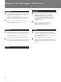
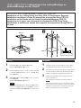
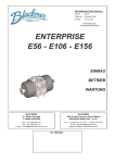
3-859-049-02(1) Projector Suspension Support Installation manual for Dealers Manuel d’installation destiné aux revendeurs Installationshandbuch für Händler Manual de instalación para proveedores Manuale d’installazione per i rivenditori CCCCCC PSS-70 1996 by Sony Corporation English Maximum load: 120 kg (264 lb 9 oz) The PSS-70 suspension support is designed for use with Sony Multiscan projector. 120 kg 650 kg M10 M10 Caution • For installation, consult with qualified Sony personnel. • The ceiling should be capable of supporting a weight of at least 650 kg (1410 lb 15 oz); if not, the ceiling must be reinforced. • When you attach the bracket directly to the ceiling, use commercially available M10 bolts with nuts and washers, depending on the ceiling. Use of other bolts, nuts, and washers other than M10 may present a danger of falling. • Be sure to assemble and attach the bracket in the order indicated; otherwise the projector may fall, resulting in grievous bodily injury or even death. • The PSS-70 suspension support is designed for use with Sony Multiscan projctor. Never use it for another purpose. PSS-70 Deutsch Français Charge maximale: 120 kg (264 lb 9 oz) Le support de suspension PSS-70 est conçu pour être utilisé avec un projecteur Multiscan Sony. Attention • Pour l’installation, adressez-vous à un personnel Sony qualifié. • Le plafond doit pouvoir supporter un poids d’au moins 650 kg (1410 lb 15 on) ; dans le cas contraire, il y a lieu de renforcer le plafond. • Lorsque vous attachez le support directement au plafond, utilisez des boulons M10 disponibles dans le commerce avec les écrous et rondelles, en fonction du plafond. L’utilisation de boulons, écrous et rondelles différents peut représenter un danger de chute auquel cas vous courez un risque de blessure voire un danger de mort. • Assemblez et fixez le support dans l’ordre indiqué; sinon, le projecteur risque de tomber auquel cas vous courez un risque de blessure voire un danger de mort. • Le support de suspension PSS-70 est conçu pour être utilisé avec un projecteur Multiscan Sony. Ne l’utilisez jamais à d’autres fins. 2 Maximale Belastbarkeit: 120 kg Die Aufhängung PSS-70 wurde speziell für Multiscan-Projektoren von Sony konzipiert. Vorsicht • Wenden Sie sich bei der Installation an qualifizierte Fachkräfte von Sony. • Die Decke sollte für eine Tragfähigkeit von mindestens 650 kg ausgelegt ist. Andernfalls muß die Decke verstärkt werden. • Wenn Sie die Halterung direkt an der Decke befestigen, verwenden Sie handelsübliche M10Schrauben mit Muttern und Unterlegscheiben (je nach Decke). Wenn Sie keine M10-Schrauben, Muttern und -Unterlegscheiben verwenden, besteht die Gefahr, daß das Gerät herunterfällt. • Achten Sie darauf, die Halterung in der angegebenen Reihenfolge zu montieren und anzubringen. Andernfalls kann der Projektor herunterfallen. Dabei könnte es zu schweren Unfällen kommen! • Die Aufhängung PSS-70 wurde speziell für Multiscan-Projektoren von Sony konzipiert. Verwenden Sie sie ausschließlich für diese Projektoren. Español Carga máxima: 120 kg (264 lb 9 oz) El soporte de suspensión PSS-70 está diseñado para utilizarse con el proyector Sony Multiscan. Precaución • Para realizar la instalación, consulte con personal Sony especializado. • El techo debe ser capaz de soportar un peso de al menos 650 kg (1410 lb 15 oz). De no ser así, es necesario reforzarlo. • Al fijar el soporte directamente en el techo, utilice pernos M10, disponibles en las tiendas del ramo, con tuercas y arandelas en función del techo. El uso de pernos, tuercas y arandelas que no sean M10 puede presentar peligro de caída. • Asegúrese de montar y fijar el soporte en el orden indicado, ya que en caso contrario es posible que el proyector se caiga, y puede existir riesgo de lesiones graves o fallecimiento. • El soporte de suspensión PSS-70 está diseñado para utilizarse con el proyector Sony Multiscan. No lo utilice para ningún otro propósito. Italiano Portata massima: 120 kg Il supporto di sospensione PSS-70 è stato progettato per essere utilizzato con il proiettore Sony Multiscan. Attenzione • Per l’installazione, consultare personale qualificato Sony. • Il soffitto deve essere in grado di sopportare un peso di almeno 650 kg. Altrimenti il soffitto dovrà essere rinforzato. • Per l’applicazione della staffa direttamente al soffitto, utilizzare bulloni, dadi e rondelle di tipo M10, comunemente disponibili in commercio, in funzione del soffitto. L’uso di altri tipi di bulloni, dadi e rondelle potrebbe rappresentare un pericolo di caduta. • Assicurarsi di montare ed applicare la staffa seguendo l’ordine indicato. Diversamente il proiettore potrebbe cadere si potrebbero correre grossi rischi. • Il supporto di sospensione PSS-70 è stato progettato per essere utilizzato con il proiettore Sony Multiscan. Non utilizzarlo per altri scopi. CCCCCC 3 /Table of contents/Table des matières/Inhalt/ Indice/Indice/CCCCC 5 7 17 21 Lista de componentes ............................................... 5 Montaje en el techo ................................................... 7 Ejemplos de instalación en el techo ........................ 17 Especificaciones ...................................................... 21 Parts List ................................................................... 5 Attaching to the ceiling .............................................. 7 Installation examples ............................................... 17 Specifications .......................................................... 21 Elenco dei componenti .............................................. 5 Montaggio al soffitto .................................................. 7 Esempi di installazione al soffitto ............................. 17 Caratteristiche tecniche ........................................... 21 Composants .............................................................. 5 Montage au plafond ................................................... 7 Examples d’installation au plafond .......................... 17 Spécifications .......................................................... 21 CCCCCCCC CCCCCCCCC CCCCCCCC CCCCCCC Teileliste .................................................................... 5 Montage an der Decke .............................................. 7 Installationsbeispiele ............................................... 17 Technische Daten ................................................... 21 4 /Parts List/Composants/Teileliste/Lista de componentes/Elenco dei componenti/CCCCC (a) (b) (c) (d) (e) Upper ceiling mount bracket (1) Support supérieur de montage pour plafond (1) Obere Deckenmontagehalterung (1) Soporte superior de montaje para techo (1) Staffa superiore di montaggio al soffitto (1) CCCCC Projector mount bracket (1) Support de montage du projecteur (1) Projektormontagehalterung (1) Soporte de montaje de proyector (1) Staffa di montaggio del proiettore (1) CCCCCCC Bolt M6 × 12 (4) Boulon M6 × 12 (4) Schraube M6 × 12 (4) Perno M6 × 12 (4) Bullone M6 × 12 (4) CCCCCC Parts number Référence de pièce Teilenummer Número de piezas Numero dei componenti CCCC 4-056-754-01 Bolt M8 × 20 (7) Boulon M8 × 20 (7) Schraube M8 × 20 (7) Perno M8 × 20 (7) Bullone M8 × 20 (7) CCCCCCC Parts number Référence de pièce Teilenummer Número de piezas Numero dei componenti CCCC 4-047-766-01 Washer M6 (4) Rondelle M6 (4) Unterlegscheibe M6 (4) Arandela M6 (4) Rondella M6 (4) CCCCC Parts number Référence de pièce Teilenummer Número de piezas Numero dei componenti CCCC 4-056-755-01 5 /Parts List/Composants/Teileliste/Lista de componentes/ Elenco dei componenti/CCCCC (f) (g) (h) (i) 6 Washer M8 (7) Rondelle M8 (7) Unterlegscheibe M8 (7) Arandela M8 (7) Rondella M8 (7) CCCCC Parts number Référence de pièce Teilenummer Número de piezas Numero dei componenti CCCC 4-047-748-01 Spacer (2) Entretoise (2) Abstandsring (2) Espaciadore (2) Distanziatore (2) CCCCC Parts number Référence de pièce Teilenummer Número de piezas Numero dei componenti CCCC 4-056-753-01 Spring washer M8 (7) Rondelle frein M8 (7) Federscheibe M8 (7) Arandela de resorte M8 (7) Rondella a molla M8 (7) CCCCCC Parts number Référence de pièce Teilenummer Número de piezas Numero dei componenti CCCC 4-047-749-01 Spring washer M6 (4) Rondelle frein M6 (4) Federscheibe M6 (4) Arandela de resorte M6 (4) Rondella a molla M6 (4) CCCCCC Parts number Référence de pièce Teilenummer Número de piezas Numero dei componenti CCCC 4-055-230-01 /Attaching to the ceiling/ Montage au plafond/Montage an der Decke/ 2 1 (b) (a) Bottom of projector Base du projecteur Unterseite des Projektors Base del proyector Base del proiettore CCCCC English 1 1 2 2 Attach the projector mount bracket (b) to the projector. Use five bolts M8×20 (d), washers M8 (f) and spring washers M8 (h). To attach the projector mount bracket to the projector, refer to the “Installation Manual” of the projector to be attached. Attach the upper ceiling mount bracket (a) to the ceiling. Use M10 bolts, nuts and washers (all commercially available). Note The direction of the upper ceilling mount bracket (a) facing a screen, refer to “Adjusting the Angle of the Projector” on pages 13-14. 7 Montaje en el techo/Montaggio al soffitto/CCCCC Français 1 2 Fixez le support de montage du projecteur (b) sur le projecteur. Utilisez les boulons M8×20 (d), les rondelles M8 (f) et les rondelles frein M8 (h). Pour fixer le support de montage du projecteur sur le projecteur, reportez-vous au “Manuel d’installation” du projecteur à installer. Fixez le support supérieur de montage pour plafond (a) au plafond. Utilisez les boulons M10, les écrous et les rondelles (tous disponibles dans le commerce). Deutsch 1 2 Remarque Pour régler le sens du support supérieur de montage pour plafond (a) face à un écran, reportez-vous à la section “Réglage de l’angle du projecteur” aux pages 13-14. 2 Fije el soporte de montaje de proyector (b) a éste. Emplee pernos M8×20 (d), arandelas M8 (f) y arandelas resorte M8 (h). Para ajustar el soporte de montaje al proyector, consulte el “Manual de instalación” del proyector correspondiente. Fije al techo el soporte superior de montaje para techo (a). Emplee arandelas, tuercas y pernos M10 (todos disponibles en las tiendas del ramo). Nota Para conocer la dirección del soporte de montaje superior para techo (a) orientado a una pantalla, consulte “Ajuste de ángulo del proyector” en las páginas 13-14. CCCCC 8 Bringen Sie die Deckenmontagehalterung (a) mit M10-Schrauben, -Muttern und -Unterlegscheiben (alle handelsüblich) an der Decke an. Hinweis In welcher Richtung die Deckenmontagehalterung (a) auf den Projektionsschirm weisen muß, erfahren Sie unter “Anpassen des Projektorwinkels” auf Seite 13-14. Español 1 Bringen Sie die Projektormontagehalterung (b) an den Projektor an. Verwenden Sie dazu M8×20-Schrauben (d), M8Unterlegscheiben (f) und M8-Federscheiben (h). Wie Sie die Projektormontagehalterung am Projektor anbringen, schlagen Sie bitte in der Installationsanleitung des zu montierenden Projektors nach. Italiano 1 2 Fissare la staffa di montaggio del proiettore (b) al proiettore. Usare bulloni M8×20 (d), rondelle M8 (f) e rondelle a molla M8 (h). Per collegare la staffa di supporto al proiettore, fare riferimento al manuale di installazione del proiettore da collegare. Fissare la staffa superiore di montaggio al soffitto (a) al soffitto. Usare bulloni M10, dadi e rondelle (tutti disponibili in commercio). Nota Per la direzione della staffa di montaggio al soffitto (a) di fronte allo schermo, fare riferimento alla sezione sulla regolazione dell’angolazione del proiettore alle pagine 13-14. /Attaching to the ceiling/Montage au plafond/Montage an der Decke/ 3 4 (a) (b) (g) (f) (h) (d) (h) (f) (d) (g) English 3 3 4 4 Attach the bolts temporarily to the upper ceiling mount bracket to fix the projector mount bracket. Use two bolts M8×20 (d), spring washer M8 (h), washers M8 (f) and spacers (g). Hook the projector mount bracket (b) attached to the projector on the upper ceiling mount bracket (a). 9 Montaje en el techo/Montaggio al soffitto/CCCCC Français 3 4 Fixez temporairement les boulons sur le support de montage supérieur pour plafond pour attacher le support de montage de projecteur. Utilisez deux boulons M8×20 (d), une rondelle frein M8 (h), des rondelles M8 (f) et des entretoises (g). Accrochez le support de montage de projecteur (b) fixé au projecteur sur le support supérieur de montage pour plafond (a). Español 3 4 Fije temporalmente los pernos al soporte de montaje superior para techo con el fin de ajustar el soporte de montaje de proyector. Emplee dos pernos M8×20 (d), una arandela de resorte M8 (h), arandelas M8 (f) y espaciadores (g). Fije el soporte de montaje de proyector (b) instalado en éste al soporte superior de montaje para techo (a). CCCCC 10 Deutsch 3 4 Bringen Sie vorläufig die Schrauben an der Deckenmontagehalterung an, mit denen die Projektormontagehalterung (b) befestigt wird. Verwenden Sie dazu M8×20-Schrauben, M8Federscheiben (h), M8-Unterlegscheiben (f) und Abstandsringe (g). Haken Sie die am Projektor angebrachte Projektormontagehalterung (b) an der Deckenmontagehalterung (a) ein. Italiano 3 4 Applicare temporaneamente i bulloni alla staffa superiore di montaggio al soffitto per fissare la staffa di montaggio del proiettore. Utilizzare due bulloni M8×20 (d), rondelle a molla M8 (h), rondelle M8 (f) e distanziatori (g). Agganciare la staffa di montaggio del proiettore (b) sul proiettore alla staffa superiore di montaggio al soffitto (a). /Attaching to the ceiling/Montage au plafond/Montage an der Decke/ 5 (a) (b) (e) (i) (c) (e) (i) (c) English 5 5 6 × 12 6 6 6 Fix the projector mount bracket (b) to the upper ceiling mount bracket (a) using 4 bolts M6×12 (c), spring washer M6 (i) and washers M6 (e). (The vertical angle of the projector can be adjusted by adjusting the securing position of the bolts in the slots. Refer to “Adjusting the Angle of the Projector” on page 13-14.) Tighten securely the bolts you attached in step 3 to fix the projector mount bracket. 11 Montaje en el techo/Montaggio al soffitto/CCCCC Français 5 6 Fixez le support de montage du projecteur (b) sur le support supérieur de montage pour plafond (a) à l’aide de 4 boulons M6×12 (c), rondelle frein M6 (i) et de rondelles M6 (e). (L’angle vertical du projecteur peut être ajusté en réglant la position de fixation des boulons dans les fentes. Voir “Réglage de l’angle du projecteur” aux pages 13-14.) Serrez les boulons que vous avez fixés à l’étape 3 pour attacher le support de montage de projecteur. Español 5 6 Ajuste el soporte de montaje de proyector (b) al soporte superior de montaje para techo (a) utilizando 4 pernos M6×12 (c), arandela de resorte M6 (i) y arandelas M6 (e). (El ángulo vertical del proyector puede determinarse mediante el ajuste de la posición de bloqueo de los pernos de las ranuras. Consulte “Ajuste de ángulo del proyector” en las páginas 13-14.) Apriete los pernos fijados en el paso 3 para ajustar el soporte de montaje de proyector. CCCCCC 12 Deutsch 5 6 Befestigen Sie die Projektormontagehalterung (b) mit 4 M6×12-Schrauben (c), Federscheibe M6 (i) und M6-Unterlegscheiben (e) an der Deckenmontagehalterung (a). Der vertikale Winkel des Projektors läßt sich einstellen, indem Sie die Position der Schrauben in den Schraubenlöchern einstellen (siehe “Anpassen des Projektor winkels” auf Seite 13-14). Ziehen Sie die in Schritt 3 angebrachten Schrauben zum Befestigen der Projektormontagehalterung an. Italiano 5 6 Fissare la staffa di montaggio del proiettore (b) alla staffa superiore di montaggio al soffitto (a) utilizzando 4 bulloni M6×12 (c), rondella a molla M6 (i) e rondelle M6 (e). (L’angolazione verticale del proiettore può essere regolata giocando sulla posizione di sicurezza dei bulloni nei loro alloggiamenti. Vedere “Regolazione dell’angolazione del proiettore” alle pagine 13-14). Serrare i bulloni applicati al passo 3 per fissare la staffa di montaggio del proiettore. /Attaching to the ceiling/Montage au plafond/Montage an der Decke/ /Adjusting the Angle of the Projector/Réglage de l’angle du projecteur/Anpassen des Projektorwinkels/Ajuste de ángulo del proyector/Regolazione dell’angolazione del proiettore/ccccc English Depending on the installation condition, adjust the angle between the bottom surface of the projector and the ceiling, and then tighten the bolts. Adjust the direction of the upper ceilling mount bracket and the securing position of the bolts. This angle is different from the optical axis angle of the projector. Français Suivant les conditions d’installation, réglez l’angle entre la surface de base du projecteur et le plafond et serrez ensuite les boulons. Ajustez le sens d’installation du support de montage supérieur pour plafond et la position de fixation des boulons. Cet angle diffère de l’angle de l’axe optique du projecteur. Español Dependiendo de las condiciones de instalación, ajuste el ángulo existente entre la superficie inferior del proyector y el techo, y a continuación, apriete los pernos. Ajuste la dirección del soporte de montaje superior para techo y la posición de bloqueo de los pernos. Este ángulo es distinto del ángulo de eje óptico del proyector. Deutch Stellen Sie je nach den Installationsbedingungen den Winkel zwischen der Unterseite des Projektors und der Decke ein, und ziehen Sie dann die Schrauben an. Stellen Sie die Richtung der Deckenmontagehalterung und die Sicherungsposition der Schrauben ein. Dieser Winkel unterscheidet sich vom Winkel der optischen Achse des Projektors. Italiano A seconda delle condizioni dell’installazione, regolare l’angolo tra la superficie inferiore del proiettore e il soffitto, quindi stringere i bulloni. Regolare la direzione della staffa di montaggio al soffitto e fissare i bulloni. Questo angolo è diverso dall’angolo dell’asse ottico del proiettore. CCCCCCC 13 Montaje en el techo/Montaggio al soffitto/CCCCC 20° 2° /When the angle between the bottom surface of the projector and the ceiling is from –20° to +2°/Si l’angle entre la surface de base du projecteur et le plafond est de –20° à +2°/Bei einem Winkel im Bereich von –20° bis +2° zwischen der Unterseite des Projektors und der Decke/Si el ángulo existente entre la superficie inferior del proyector y el techo es de –20° a +2°/Quando l’angolo tra la superficie inferiore del proiettore e il soffitto è di –20° a +2°/ CCCCCCCCCCCCC 20° –10° + 20° +2° – 10° +2° /Screen forward Ecran/Projektionsschirm Pantalla/Direzione dello schermo CCCCC 2° 20° /When the angle between the bottom surface of the projector and the ceiling is from –2° to +20°/Si l’angle entre la surface de base du projecteur et le plafond est de –2° à +20°/Bei einem Winkel im Bereich von –2° bis +20° zwischen der Unterseite des Projektors und der Decke/Si el ángulo existente entre la superficie inferior del proyector y el techo es de –2° a +20°/Quando l’angolo tra la superficie inferiore del proiettore e il soffitto è di –2° a +20°/ CCCCCCCCCCCCC 10° 20° + 2° +20° – –2° /Screen forward Ecran/Projektionsschirm Pantalla/Direzione dello schermo CCCCC 14 10° /Attaching to the ceiling/Montage au plafond/Montage an der Decke/ / PSS-10 Installation on the Ceiling Using the Sony PSS-10 Suspension Support/ Installation au plafond à l’aide du support de suspension Sony PSS-10/ Installation an der Decke mit der Sony-Projektoraufhängung PSS-10/ Instalación en el techo con el soporte de suspensión PSS-10 de Sony/ Installazione a soffitto per mezzo del supporto di sospensione Sony PSS-10 ccccccc 2 PSS-10 (a) 1 3 (a) (a) PSS-10 (A) English 1 2 1 2 3 3 Attach the upper part of the PSS-10 to the ceiling. (See the PSS-10 installation manual for details.) Insert the lower part of the PSS-10 into the hole in the base box and secure them using the M10 bolts, M10 washers, and M10 nuts supplied with the PSS-10. Adjust the length and secure the upper and lower parts of the PSS-10. (See the PSS-10 installation manual for details.) Note The distance between the projector and the ceiling will be decreased by 5.5 mm (7/32 inch) (A) from the installation measurements of the PSS-10 when the PSS-70 and the PSS-10 are used together. 15 Montaje en el techo/Montaggio al soffitto/CCCCC Français 1 2 3 Fixez la partie supérieure du PSS-10 au plafond. (Voir le manuel d’installation PSS-10 pour plus de détails.) Deutsch 1 Insérez la partie inférieure du PSS-10 dans l’orifice du socle et fixez-la à l’aide des écrous M10, des rondelles M10 et des écrous M10 fournis avec le PSS-10. 2 Réglez la longueur et fixez les parties supérieure et inférieure du PSS-10. (Voir le manuel d’installation PSS-10 pour plus de détails.) 3 Remarque La distance entre le projecteur et le plafond diminue de 5,5 mm (7/32 pouce) (A) à partir des mesures d’installation du PSS-10 lorsque le PSS-70 et le PSS10 sont utilisés conjointement. 2 3 Fije la parte superior del PSS-10 al techo. (Para obtener más información, consulte el manual de instalación del PSS-10.) Ajuste la longitud y asegure las partes superior e inferior del PSS-10. (Para obtener más información, consulte el manual de instalación del PSS-10.) 3 CCCCCC 16 1 2 Nota Stellen Sie die gewünschte Länge ein, und sichern Sie den unteren und oberen Teil der PSS-10. (Einzelheiten dazu finden Sie in der Bedienungsanleitung zur PSS-10.) Italiano Inserte la parte inferior del PSS-10 en el orificio de la caja base y bloquéelos con los pernos M10, las arandelas M10 y las tuercas M10 suministrados con el PSS-10. La distancia entre el proyector y el techo disminuirá en 5,5 mm (7/32 pulgada) (A) con respecto a las medidas de instalación del PSS-10 si utiliza conjuntamente las unidades PSS-70 y PSS-10. Fügen Sie den unteren Teil der PSS-10 in die Aussparung des Basisgehäuses ein, und sichern Sie die Teile mit den M10-Schrauben, M10-Unterlegscheiben und M10-Muttern, die mit der PSS-10 geliefert werden. Hinweis Der Abstand zwischen der Decke und dem Projektor verringert sich gegenüber den Installationsmaßen für die PSS-10 um 5,5 mm (A), wenn die PSS-70 und die PSS10 zusammen benutzt werden. Español 1 Bringen Sie den oberen Teil der PSS-10 an der Decke an. Einzelheiten dazu finden Sie in der Installationsanleitung zur PSS-10. Fissare la parte superiore del PSS-10 al soffitto. (Per i dettagli, consultare il manuale d’installazione del PSS-10). Inserire la parte inferiore del PSS-10 nel foro situato nella base e fissare entrambe le parti mediante i bulloni M10, le rondelle M10 e i dadi M10 in dotazione con il PSS-10. Regolare la lunghezza e fissare le parti superiore ed inferiore del PSS-10. (Per i dettagli, consultare il manuale d’installazione del PSS-10). Nota La distanza fra il proiettore ed il soffitto verrà diminuita di 5,5 (A) mm rispetto alle misurazioni indicate per l’installazione del PSS-10 qualora il PSS70 e il PSS-10 siano utilizzati insieme. /Installation Examples/Exemples d’installation au plafond/Installationsbeispiele/ Las siguientes ilustraciones muestran el soporte de suspensión para proyector fijado al techo. La instalación varía en función del material del techo. Nota Compruebe la capacidad de carga máxima del techo sea superior a 650 kg (1410 lb 15 oz) antes de realizar la instalación. The following illustrations show the projector suspension support attached to the ceiling. Installation is different depending on the material of ceiling. Caution Before installation, check that the maximum ceiling loading is in excess of 650 kg (1410 lb 15 oz). Les illustrations suivantes représentent le support de suspension du projecteur fixé au plafond. L’installation s’effectue différemment en fonction de la constitution du plafond. Remarque Le seguenti illustrazioni mostrano il montaggio al soffitto del supporto di sospensione del proiettore. La procedura di installazione varia a seconda del tipo di soffitto. Attenzione Prima di procedere con l’installazione, verificare che il peso massimo di portata del soffitto sia superiore a 650 kg. ccccccccccc Vérifiez que la charge maximale du plafond soit supérieure à 650 kg (1410 lb 15 on) avant l’installation. In den Abbildungen unten ist dargestellt, wie die Projektoraufhängung an der Decke angebracht wird. Die Installation unterscheidet sich je nach Material der Decke. Hinweis Überprüfen Sie vor der Installation, ob die maximale Belastbarkeit der Decke mindestens 650 kg beträgt. 17 Ejemplos de instalación en el techo/Esempi di installazione al soffitto/CCCCC /For wooden ceiling/Pour un plancher/Montage an einer Holzdecke/Para techos de madera/Montaggio ad un soffitto in legno/ ccccc /For-one-story house or uppermost floor/Pour maison à un étage ou plafond sous un toit/Decke eines einstöckigen Hauses oder des obersten Stockwerks/ Para casas de una planta o plantas superiores/Montaggio in una casa a piano unico o all’ultimo piano/ccccc /Reinforcing material/Matériel de renfort/Verstärkungsmaterial/Material de refuerzo/Materiale di rinforzo/ccc /Roof beam (2” x 8”) / Poutre de toit/Dachträgerbalken (ca. 5 x 20 cm) /Viga de techo (2” x 8”) /Trave del soffitto (circa 5 x 20 cm.) /ccc /Ceiling line/Niveau du plafond/ Deckenlinie/Línea de techo/Livello del soffitto/ccc Projector Projecteur Projektor Proyector Proiettore ccc Units : mm (inches) Unité : mm (pouces) Einheit : mm Unidades : mm (pulgadas) Unità : mm ccccccc 18 M10 bolt with nut and washer/Boulon M10 avec écrou et rondelle/M10-Schraube mit Mutter und/Perno M10 con tuerca y arandela/Bullone M10 con dado e rondella/ ccc Upper ceiling mount bracket Support supérieur de montage pour plafond Obere Deckenmontagehalterung Soporte superior de montaje para techo Staffa superiore di montaggio al soffitto ccc Nail Clou Nagel Punta Chiodo ccc /Installatión Examples/Exemples d’installation au plafond/Installationsbeispiele/ /For other floors/Autres sols/Zwischendecken/Para otros suelos/Per altri piani/ ccc /Floor line/Niveau du plancher/ Stockwerkslinie/Línea de suelo/Livello del pavimento/ccc /Joist (2” x 8”)/Traverse/Deckenbalken(ca. 5 x 20 cm)/Viga(2” x 8”)/Travetto(circa 5 x 20 cm.)/Travetto(circa 5 x 20 cm)/ccc /Roof beam (2” x 8”) / Traverse (2” x 8”) /Dachträgerbalken (ca. 5 x 20 cm) /Viga de techo (2” x 8”) /Trave del soffitto (circa 5 x 20 cm.) /ccc /Ceiling line/Niveau du plafond/ Deckenlinie/Línea de techo/Livello del soffitto/ccc Projector Projecteur Projektor Proyector Proiettore ccc M10 bolt with nut and washer/Boulon M10 avec écrou et rondelle/M10-Schraube mit Mutter und Unterlegscheibe/Perno M10 con tuerca y arandela/Bullone M10 con dado e rondella/ccc Upper ceiling mount bracket Support supérieur de montage pour plafond Obere Deckenmontagehalterung Soporte superior de montaje para techo Staffa superiore di montaggio al soffitto ccc Units : mm (inches) Unité : mm (pouces) Einheit : mm Unidades : mm (pulgadas) Unità : mm ccccccc 19 Ejemplos de instalación en el techo/Esempi di installazione al soffitto/CCCCC /For concrete celing/Pour un plafond en béton/Betondecke/Para techos de hormigón/Montaggio ad un soffitto di cemento/CCCCC /Concrete ceiling/ Plafond en béton/Betondecke/ Techo de hormigón/Soffitto di cemento/cccc Upper ceiling mount bracket Support de montage supérieur pour plafond Obere Deckenmontagehalterung Soporte de montaje superior para techo Staff ccccc Place bolts at least 80 mm (3 1/4 inches) away from wall. /Ecartez les boulons de 80 mm (3 1/4 pouces) du mur minimum. / Schrauben mindestens 80 mm von der Wand entfernt anbringen. /Coloque los pernos a una distancia de al menos 80 mm (3 1/4 pulgadas) de la pared. /Collocare i bulloni ad almeno 80 mm dal muro. / cccccc Units : mm (inches) Unité : mm (pouces) Einheit : mm Unidades : mm (pulgadas) Unità : mm ccccccc 20 Projector Projecteur Projektor Proyector Proiettore ccccc /Anchor for concrete (over 12 mm; 1/2 inch dia.) / Ancrage pour béton (supérieur à 12 mm; 1/2 pouce de diamètre) /Betonanker (mehr als 12 mm Durchmesser) / Anclaje para hormigón (con diámetro superior a 12 mm; 1/2 pulgada) /Catena per cemento (oltre 12 mm di diametro)/ cccccc /Specifications/Spécifications/Technische Daten/ Especificaciones/Caratteristiche tecniche/CCCC /Dimensions/Mesures/Abmessungen/Dimensiones/Dimensioni/cccc /Projector mount bracket/Support de montage du projecteur/ Projektormontagehalterung/Soporte de montaje de proyector/Staffa di montaggio del proiettore/ CCCCCCCCCC A B A φ A A B A ° φ Units : mm (inches) Unité : mm (pouces) Einheit : mm Unidades : mm (pulgadas) Unità : mm ccccccc A: /Holes for attaching the projector mount bracket/Orifice de fixation du sopport de montage du projecteur/Bohrung zum Anbringen derprojektormontagehalterung/Orificio para conectar el soporte de montaje de proyector/Foro per fissare la staffa di montaggio del proiettore/CCCCCCCCCCCCC B: /Holes for confirming to align the two projections on the projector mount bracket with the holes on the bottom surface of the projector. /Orifices de contrôle pour l’alignement des deux saillies du support de montage du projecteur sur les orifices de la surface inférieure du projecteur/ Kontrollbohrungen zum Ausrichten der beiden vorstehenden Teile der Projektormontagehalterung an den Bohrungen auf der Unterseite des Projektors/ Comprobación de los orificios al alinear los dos salientes en el soporte de montaje del proyector con los orificios en la superficie inferior del proyector/Fori per consentire l’allineamento tra le due sporgenze sulla staffa di montaggio del proiettore e i fori sulla superficie inferiore del proiettore/CCCCCCCC 21 /Specifications/Spécifications/Technische Daten/ Especificaciones/Caratteristiche tecniche/CCCCC /Upper ceiling mount bracket/Support supérieur de montage pour plafond/ Obere Deckenmontagehalterung/Soporte superior de montaje para techo/Staffa superiore di montaggio al soffitto/CCCCCCCCCCCCCCCCC φ ° A A A φ A Units : mm (inches) Unité : mm (pouces) Einheit : mm Unidades : mm (pulgadas) Unità : mm ccccccc 22 A: φ φ /Hole for attaching the upper ceiling mount bracket/Orifice de fixation du support supérieur de montage pour plafond/Bohrung zum Anbringen obere deckenmontagehalterung/Orificio para conectar el soporte superior de montaje para techo/Foro per fissare la staffa superiore di montaggio al soffitto/ CCCCCCCCCCCCC 9 kg/Mass Approx. 9 kg (6 lb 10 oz)/Poids : 9 kg approx. (6 lb 10 on)/Gewicht : ca. 9 kg/Masa: 9 kg aprox. (6 lb 10 oz)/Peso approssimativo: 9 kg/CCCCC 120 kg/Loading Maximum :120 kg (264 lb 9 oz) /Charge maximale: 120 kg (264 lb 9 on) /Carga máxima: 120 kg/Carico massimo: 120 kg (264 lb 9 oz) /Portata massima: 120 kg/CCCCC Diseño y especificaciones sujetos a cambios sin previo aviso. Design and specifications are subject to change without notice. Il design e le caratteristiche tecniche sono soggetti a modifiche senza preavviso. La conception et les spécifications sont sujettes à modifications sans préavis. cccccccc Änderungen, die dem technischen Fortschritt dienen, bleiben vorbehalten. 23 Prined in U.S.A