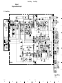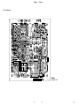
1
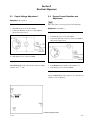
AC ADAPTOR
AC-550CE
MAINTENANCE MANUAL
1st Edition
Serial No. 45451 and Higher
! WARNING
This manual is intended for qualified service personnel only.
To reduce the risk of electric shock, fire or injury, do not perform any servicing other than that
contained in the operating instructions unless you are qualified to do so. Refer all servicing to
qualified service personnel.
! WARNUNG
Die Anleitung ist nur für qualifiziertes Fachpersonal bestimmt.
Alle Wartungsarbeiten dürfen nur von qualifiziertem Fachpersonal ausgeführt werden. Um die
Gefahr eines elektrischen Schlages, Feuergefahr und Verletzungen zu vermeiden, sind bei
Wartungsarbeiten strikt die Angaben in der Anleitung zu befolgen. Andere als die angegeben
Wartungsarbeiten dürfen nur von Personen ausgeführt werden, die eine spezielle Befähigung
dazu besitzen.
! AVERTISSEMENT
Ce manual est destiné uniquement aux personnes compétentes en charge de l’entretien. Afin
de réduire les risques de décharge électrique, d’incendie ou de blessure n’effectuer que les
réparations indiquées dans le mode d’emploi à moins d’être qualifié pour en effectuer d’autres.
Pour toute réparation faire appel à une personne compétente uniquement.
AC-550CE
Table of Contents
Manual Structure
Purpose of this manual .............................................................................................. 3
Related manual .......................................................................................................... 3
Contents ..................................................................................................................... 3
1. Service Overview
1-1.
1-2.
Connectors and Cable ................................................................................. 1-1
1-1-1. Connecting Connectors/Cables .................................................. 1-1
1-1-2. Connectors Input/Output Signal ................................................. 1-1
Notes on Service ......................................................................................... 1-2
1-2-1. Note on Maintenance ................................................................. 1-2
1-2-2. Notes on Repair Parts ................................................................. 1-2
2. Electrical Alignment
2-1.
2-2.
Output Voltage Adjustment ........................................................................ 2-1
Excess Current Detection and Adjustment ................................................. 2-1
3. Spare Parts
3-1.
3-2.
Exploded View ............................................................................................ 3-2
Electrical Parts List ..................................................................................... 3-4
4. Semiconductor Pin Assignments
5. Diagram and Board Layout
5-1.
5-2.
AC-550CE
Frame Wiring .............................................................................................. 5-1
Board Layout ............................................................................................... 5-2
1
Manual Structure
Purpose of this manual
This manual is the maintenance manual for AC Adaptor AC-550CE.
This manual describes the information items on maintenance, and items that premise
the service based on the components parts such as alignment, schematic diagram,
board layout and spare parts list, assuming use of service engineers.
Related manual
Besides this maintenance manual, the following manual is available for this unit.
. Operation Manual (Supplied with this unit)
This manual is necessary for application and operation of this unit.
Contents
The following are summaries of the each section for understanding the manual.
Section 1 Service Overview
Describes information about connector input/output signals and Notes on Service.
Section 2 Electrical Alignment
Describes electrical adjustment.
Section 3 Spare Parts
Describes parts list, exploded view, and supplied accessories used in the unit.
Section 4 Semiconductor Pin Assignments
Describes function diagrams and pin names of semiconductor used in the unit.
Section 5 Diagram and Board Layout
Describes schematic diagram and board layout.
AC-550CE
3
Section 1
Service Overview
1-1. Connectors and Cable
CAMERA (26-pin, Female)
1-1-1. Connecting Connectors/Cables
To connect cables to each connector of the connector block
for installing or servicing, use the following the connectors, cables or equivalent.
Connector
Connector/Cable
VIDEO OUT
EXT VBS
(BNC)
1-569-370-12 PLUG, BNC
CAMERA
(26-pin, female)
1-564-183-00 PLUG, 26-pin male or CCZ
cable assembly (accessory)
CCZ-10 (10 m)
DC OUT
(4-pin, female)
CCDD-X2 (2 m, supplied with the unit)
MIC OUT
(3-pin, male)
1-508-083-00 XLR, 3-pin female or
Cannon XLR-3-11C or equivalent
1-1-2. Connectors Input/Output Signal
AC IN
110 to 120 V / 220 to 240 V AC 10% selectable
VIDEO OUT
BNC type, 75 Z
EXT VBS
BNC type, 75 Z
Voltage selector
AC-550CE
_ EXT VIEW _
(0 dBu = 0.775 Vrms)
No.
Signal
Specifications
1
VIDEO IN (X)
1.0 V p-p, Zi = 75 Z
2
VIDEO IN (GND)
1.0 V p-p, Zi = 75 Z
3
NC
No connection
4
NC
No connection
5
NC
No connection
6
NC
No connection
7
NC
No connection
8
NC
No connection
9
MIC IN (X)
_60 dBu High impedance
balanced
10
MIC IN (Y)
_60 dBu High impedance
balanced
11
MIC IN (GND)
_60 dBu High impedance
balanced
12
NC
No connection
13
NC
No connection
14
NC
No connection
15
NC
No connection
16
NC
No connection
17
FRAME GND
18
EXT VBS OUT (X)
19
EXT VBS OUT (GND) 1.0 V p-p, Zo = 75 Z
20
NC
No connection
21
NC
No connection
22
NC
No connection
23
NC
No connection
24
NC
No connection
A
DC OUT (+13.5 V)
+13.2 V to +13.8 V, 7 A
B
DC OUT (GND)
1.0 V p-p, Zo = 75 Z
1-1
1-1. Connectors and Cable
1-2. Notes on Service
1-2. Notes on Service
DC OUT (4-pin, Female)
1-2-1. Note on Maintenance
4
1
3
2
_ EXT VIEW _
No.
Signal
Specifications
1
GND
GND for UNREG
2
NC
No connection
3
NC
No connection
4
DC OUT
+13.2 V to +13.8 V, 7 A
High voltage exists on the primary side of the mounted
circuit board when the unit is energized. Take utmost care
when checking and repairing and do not touch the primary
side with bare hand or tools.
MIC OUT (3-pin, Male)
_ EXT VIEW _
No.
Signal
Specifications
1
MIC OUT
_60 dBu High impedance
balanced
2
MIC OUT
3
MIC OUT
1-2-2. Notes on Repair Parts
1. Safety Related Components Warning
w
Components marked ! are critical to safe operation.
Therefore, specified parts should be used in the case of
replacement.
2. Standardization of Parts
Some repair parts supplied by Sony differ from those
used for the unit. These are because of parts commonality and improvement.
Parts list has the present standardized repair parts.
3. Stock of Parts
Parts marked with “o” at SP (Supply Code) column of
the spare parts list may not be stocked. Therefore, the
delivery date will be delayed.
1-2
AC-550CE
Section 2
Electrical Alignment
2-1. Output Voltage Adjustment
2-2. Excess Current Detection and
Adjustment
Equipment : DC voltmeter
n
Only when part has been replaced, perform adjustment.
Preparation
Equipment : DC ammeter
1. Turn OFF the power of the AC-550CE.
2. Connect the DC OUT connector of AC-550CE as
shown in the figure below.
Preparation
1. Turn OFF the power of the AC-550CE.
2. Connect the DC OUT connectors of the AC-550CE as
shown in the figure below.
3. Turn ON the power of the AC-550CE.
Adjustment
Adjust 1VR201/A board so that the DC voltmeter reading
becomes +13.5 +0.2
_0 V dc.
3. Turn 1VR202/A board fully counterclockwise 3.
4. Turn ON the power of the AC-550CE.
Adjustment
Slowly turn 1VR202/A board clockwise 2 so that the load
current becomes 15.0 ± 0.5 A.
A board (component side)
AC-550CE
2-1
Section 3
Spare Parts
AC-550CE
3-1
3-2
9-903-758-01
9-903-760-01
9-903-762-01
9-903-763-01
9-903-764-01
31
32
33
34
35
o
o
s
o
o
PLATE REINFORCEMENT
HARNESS, CN3
HOLDER, LED
HARNESS, CN1
HARNESS, CN2
SCREW
SCREW
SCREW
SCREW
SCREW
7-682-265-09
7-682-548-04
7-682-548-09
7-682-661-01
7-682-948-01
7-682-951-01
7-682-661-09
8-719-800-58
9-885-008-02
9-903-699-01
21
22
23
24
25
26
27
28
29
30
s
s
s
o
o
SCREW +PSW3X14
SCREW +PS4X8
LED TLG147 ; GREEN
HARNESS, CN5
MOUNTED CIRCUIT BOARD, A
+K4X16
+B3X8
+B3X8
+PS4X8
+PSW3X8
HANDLE (1)
RETAINER
RETAINER, TRANSISTOR
SCREW +K2.6X6
WASHER, LW3
16
3-648-409-00 o
17
4-886-820-01 o
18 ! 4-886-830-02 o
19
7-621-561-19 s
20
7-623-308-07 s
s
s
s
s
s
COVER
LABEL, POLARITY (4P)
FOOT, RUBBER
HANDLE
FOOT, LOWER
o
o
s
s
s
2-253-312-31
2-253-330-01
3-143-272-02
3-419-372-01
3-644-003-00
41 ! 9-903-776-01 o SHEET, RADIATION
42 ! 9-903-777-01 o TUBE, RADIATION
43
9-903-779-01 s SCREW +PSW3X8
44
9-903-783-01 s LABEL, POLARITY (26P)
CONNECTOR, 4P FEMALE “DC OUT”
CONNECTOR, BNC “VIDEO OUT” “EXT VBS”
CONNECTOR, 26P FEMALE “CAMERA OUT”
CONNECTOR, 3P MALE “MIC OUT”
SWITCH, POWER “POWER ON/OFF”
SP Description
11
12
13
14
15
s
s
o
s
s
Part No.
No.
36
9-903-765-01 o HARNESS, CN4
37 ! 9-903-748-01 s FUSE 5A 250V
38
9-903-769-01 o WIRE, GROUND
39
9-903-771-01 o PANEL, REAR
40
9-903-775-01 o BRACKET, B
1-509-185-31
1-561-781-91
1-562-245-11
1-563-030-21
! 1-570-117-11
1
2
3
4
5
SP Description
6 ! 1-570-173-21 s SWITCH, VOLTAGE SELECTOR
7 ! 1-580-375-21 o INLET, AC “AC IN”
8
4-604-107-11 s GUARD, POWER SWITCH
9
2-253-306-21 o TABLE, HANDLE
10
2-253-312-21 o COVER
Part No.
No.
------------OVERALL BLOCK
-------------
3-1. Exploded View
Overall Block
AC-550CE
Overall Block
AC-550CE
3-3
3-2. Electrical Parts List
------A BOARD
------Ref. No.
or Q’ty Part No.
(A BOARD)
Ref. No.
or Q’ty Part No.
SP Description
1pc ! 9-903-699-01 o MOUNTED CIRCUIT BOARD, A
2pcs
7-682-949-01 s SCREW +PSW3X10
1pc
9-903-750-01 o PLATE, SHIELD
1pc
9-903-751-01 o HEAT SINK
2pcs
9-997-769-01 s HOLDER, FUSE
SP Description
D111
D112
D113
D114
D115
9-903-712-01
8-719-110-03
8-719-031-11
8-719-031-11
9-903-715-01
s
s
s
s
s
DIODE
DIODE
DIODE
DIODE
DIODE
UF4007G23
RD7.5ESB2
ERA91-02V3R
ERA91-02V3R
ERC91-02AXE5
D116
D201
D202
D203
D204
9-903-715-01
9-903-714-01
9-903-714-01
8-719-031-11
8-719-031-11
s
s
s
s
s
DIODE
DIODE
DIODE
DIODE
DIODE
ERC91-02AXE5
YG902C2
YG902C2
ERA91-02V3R
ERA91-02V3R
C107 ! 9-903-703-01 s CERAMIC 4700P
C108
9-885-008-06 s ELECT 820uF 250V
C109
9-885-008-06 s ELECT 820uF 250V
C110
9-903-702-01 s FILM 1.5uF 250V
C111
9-885-008-03 s CERAMIC 0.022uF 50V
D205
D206
D207
D208
D209
8-719-031-10
8-719-031-10
8-719-110-03
8-719-110-48
8-719-110-53
s
s
s
s
s
DIODE
DIODE
DIODE
DIODE
DIODE
ERB91-02V3R
ERB91-02V3R
RD7.5ESB2
RD18ESB1
RD20ESB2
C112
C113
C114
C115
C116
D210
8-719-109-93 s DIODE RD6.2ESB2
C101
C103
C104
C105
C106
! 9-885-008-05
! 9-885-008-05
! 9-903-703-01
! 9-903-703-01
! 9-903-703-01
s
s
s
s
s
FILM 0.47uF 275V
FILM 0.47uF 275V
CERAMIC 4700P
CERAMIC 4700P
CERAMIC 4700P
9-885-008-03
9-903-704-01
9-903-704-01
9-939-840-01
1-136-196-11
s
s
s
s
s
CERAMIC 0.022uF 50V
CERAMIC 2200P 1KV
CERAMIC 2200P 1KV
ELECT 10uF 50V
FILM 0.033uF 400V
C117
1-162-896-11
C118
9-939-839-01
C119
9-939-839-01
C120
1-136-203-11
C121 ! 9-903-708-01
s
s
s
s
s
CERAMIC 0.1uF 50V
ELECT 47uF 16V
ELECT 47uF 16V
FILM 0.01uF 630V
CERAMIC 2200P
C122 ! 9-903-708-01 s CERAMIC 2200P
C201
9-997-680-01 s CERAMIC 1000P 1KV
C202
9-997-680-01 s CERAMIC 1000P 1KV
C203
9-939-842-01 s ELECT 2700uF 16V
C204
9-939-842-01 s ELECT 2700uF 16V
C205
C206
C207
C208
C209
9-939-842-01
9-939-842-01
9-939-841-01
9-939-843-01
9-885-008-04
s
s
s
s
s
ELECT 2700uF 16V
ELECT 2700uF 16V
ELECT 0.47uF 50V
ELECT 220uF 35V
CERAMIC 0.0047uF 50V
C210
C211
C212
C213
C214
9-885-008-04
1-162-896-11
9-939-840-01
9-939-841-01
1-162-879-11
s
s
s
s
s
CERAMIC 0.0047uF 50V
CERAMIC 0.1uF 50V
ELECT 10uF 50V
ELECT 0.47uF 50V
CERAMIC 100P 50V
CN101 ! 9-903-743-01 o CONNECTOR 2P,
CN102 ! 9-903-743-01 o CONNECTOR 2P,
CN103 ! 9-903-743-01 o CONNECTOR 2P,
CN201 9-903-744-01 o CONNECTOR 4P,
CN202 9-903-745-01 o CONNECTOR 2P,
MALE
MALE
MALE
MALE
MALE
D101
D102
D103
D104
D105
9-903-713-01
9-903-713-01
9-903-710-01
8-719-031-10
8-719-031-10
s
s
s
s
s
DIODE
DIODE
DIODE
DIODE
DIODE
D5SB60-4001
D5SB60-4001
ERC38-05E4
ERB91-02V3R
ERB91-02V3R
D106
D107
D108
D109
D110
9-903-711-01
9-903-710-01
8-719-031-10
8-719-031-10
9-903-711-01
s
s
s
s
s
DIODE
DIODE
DIODE
DIODE
DIODE
ERA38-05V3R
ERC38-05E4
ERB91-02V3R
ERB91-02V3R
ERA38-05V3R
3-4
F101 ! 9-903-748-01 s FUSE 5A 250V
FR101 ! 9-903-716-01 s RES, FUSIBLE 15uF 7W 133dC
IC201
8-759-937-59 s IC MB3759
L101 ! 9-903-717-01 s INDUCTOR 8.2mH
L102 ! 9-903-719-01 s INDUCTOR
L103
9-885-008-00 s INDUCTOR, CHOKE
L201
9-903-721-01 s INDUCTOR, CHOKE
L202
9-903-720-01 s INDUCTOR, DRUM
Q101
Q102
Q103
Q104
Q201
9-903-722-01
9-903-722-01
9-903-723-01
8-729-119-78
8-729-374-02
s
s
s
s
s
TRANSISTOR
TRANSISTOR
TRANSISTOR
TRANSISTOR
TRANSISTOR
2SC3320
2SC3320
2SC3866-F65
2SC2785
2SB740-3
Q202
Q203
Q204
Q205
8-729-374-02
8-729-173-38
8-729-119-78
8-729-119-78
s
s
s
s
TRANSISTOR
TRANSISTOR
TRANSISTOR
TRANSISTOR
2SB740-3
2SA733
2SC2785
2SC2785
R101
R102
R103
R104
R105
9-997-700-01
1-215-861-00
1-215-861-00
1-215-903-11
1-215-903-11
s
s
s
s
s
CARBON 1K 1/6W
METAL 47 5% 1W
METAL 47 5% 1W
METAL 68K 5% 2W
METAL 68K 5% 2W
R106
R107
R108
R109
R110
1-216-369-00
9-903-731-01
9-903-731-01
1-216-369-00
9-903-731-01
s
s
s
s
s
METAL 1.0
CARBON 10
CARBON 10
METAL 1.0
CARBON 10
5% 2W
1/2W
1/2W
5% 2W
1/2W
R111
9-903-731-01 s
R112
9-903-737-01 s
R113 ! 9-903-728-01 s
R114
9-903-732-01 s
R115
9-903-732-01 s
CARBON 10 1/2W
WIREWOUND 47 5W
RES, FUSIBLE 15 1/4W
CARBON 180K 1/2W
CARBON 180K 1/2W
R116
R117
R118
R119
R120
CARBON 33K 1/6W
FILM 150K 3W
CARBON 220 1/2W
CARBON 1.5K 1/6W
CARBON 33 1/2W
9-997-708-01
9-903-724-01
9-903-733-01
9-997-703-01
9-903-734-01
s
s
s
s
s
AC-550CE
----FRAME
----Ref. No.
or Q’ty Part No.
(A BOARD)
Ref. No.
or Q’ty Part No.
SP Description
R121
9-997-706-01
R122
9-997-700-01
R123
9-997-700-01
R124 ! 9-997-756-01
R125
9-885-008-01
s
s
s
s
s
CARBON 330 1/6W
CARBON 1K 1/6W
CARBON 1K 1/6W
RES, FUSIBLE 10 1/4W
CARBON 470K 1/2W
R201
R202
R203
R204
R205
1-217-654-11
1-217-654-11
9-997-707-01
9-997-703-01
9-903-725-01
s
s
s
s
s
WIREWOUND 0.02 10% 5W
WIREWOUND 0.02 10% 5W
CARBON 3.3K 1/6W
CARBON 1.5K 1/6W
METAL 180 5W
R206
R207
R208
R209
R210
9-903-725-01
9-903-736-01
9-997-706-01
9-997-697-01
9-997-706-01
s
s
s
s
s
1pc
SP Description
9-903-769-01 o WIRE, GROUND
CN301 ! 1-580-375-21 o INLET, AC 3P “AC IN”
CN302
1-509-185-31 s CONNECTOR, 4P FEMALE “DC OUT”
CN303
1-562-245-11 o CONNECTOR, 26P FEMALE “CAMERA OUT”
CN304
1-561-781-91 s CONNECTOR, BNC (RECEPTACLE)
CN305
1-563-030-21 s CONNECTOR, 3P MALE “MIC OUT”
CN306
1-561-781-91 s CONNECTOR, BNC (RECEPTACLE)
D211
8-719-800-58 s LED TLG147 ; GREEN
METAL 180 5W
METAL 4.7 5W
CARBON 330 1/6W
CARBON 470 1/4W
CARBON 330 1/6W
HN001
HN002
HN003
HN004
HN005
9-903-763-01
9-903-764-01
9-903-760-01
9-903-765-01
9-885-008-02
R211
9-997-697-01 s
R212
1-215-889-00 s
R213 ! 9-903-729-01 s
R214
9-903-727-01 s
R215
9-997-704-01 s
CARBON 470 1/4W
METAL 330 5% 2W
RES, FUSIBLE 47 1/6W
CARBON 4.7K 1/6W
CARBON 2.2K 1/6W
S101 ! 1-570-117-11 s SWITCH, POWER “POWER ON/OFF”
S102 ! 1-570-173-21 s SWITCH, VOLTAGE SELECTOR
R216
9-903-730-01
R217
9-997-706-01
R218
9-903-735-01
R219 ! 9-903-729-01
R220
9-997-699-01
s
s
s
s
s
CARBON 680 1/4W
CARBON 330 1/6W
CARBON 2.2K 1/4W
RES, FUSIBLE 47 1/6W
CARBON 100 1/6W
R221
R222
R223
R224
R225
9-997-703-01
9-997-702-01
9-997-708-01
9-903-727-01
9-903-726-01
s
s
s
s
s
CARBON
CARBON
CARBON
CARBON
CARBON
1.5K 1/6W
100K 1/6W
33K 1/6W
4.7K 1/6W
2.7K 1/6W
R226
R227
R228
R229
R230
9-997-702-01
9-997-706-01
9-997-713-01
9-997-700-01
9-997-700-01
s
s
s
s
s
CARBON
CARBON
CARBON
CARBON
CARBON
100K 1/6W
330 1/6W
680 1/6W
1K 1/6W
1K 1/6W
R231
R232
R233
9-997-700-01 s CARBON 1K 1/6W
9-997-700-01 s CARBON 1K 1/6W
9-903-727-01 s CARBON 4.7K 1/6W
SR201
8-719-000-28 s THYRISTOR CR02AM-4
! 9-903-739-01
! 9-903-741-01
! 9-903-741-01
! 9-903-740-01
s
s
s
s
TRANSFORMER,
TRANSFORMER,
TRANSFORMER,
TRANSFORMER,
CN1
CN2
CN3
CN4
CN5
! 1-782-929-11 s CORD, POWER (BS 3P)
CONVERTER
DRIVE
DRIVE
CONVERTER
TR101
9-997-766-01 s TRIAC 8A 600V
VR201
VR202
9-903-742-01 s RES, ADJ, METAL 2K
9-903-742-01 s RES, ADJ, METAL 2K
AC-550CE
HARNESS,
HARNESS,
HARNESS,
HARNESS,
HARNESS,
-------------------SUPPLIED ACCESSORIES
-------------------Ref. No.
or Q’ty Part No.
SP Description
1pc
T101
T102
T103
T104
o
o
o
o
o
3-5
Diode, Transistor, IC
Section 4
Semiconductor Pin Assignments
[DIODE]
[TRANSISTOR]
[IC]
AC-550CE
4-1
Frame Wiring
Frame Wiring
Section 5
Diagram and Board Layout
1
5-1. Frame Wiring
!
!
S101
!
!
!
HN003
!
CN302
DC OUT
(FEMALE)
HN001
!
!
2
0.47
CN301
AC IN
HN004
!
!
!
!
!
!
!
!
CN303
CAMERA OUT
(FEMALE)
HN005
!
!
HN002
CN304
VIDEO OUT
!
3
(WIRING SIDE)
!
!
CN305
MIC OUT
(MALE)
S102
4
!
!
A BOARD
!
CN306
EXT VBS
5
Frame Wiring
A Board
AC-550CE
B-¥AC550-FRAME
5-1
AC-550CE
A
B
C
D
5-1
E
F
G
H
A Board
A Board
5-2. Board Layout
A Board
-COMPONENT SIDE-
5-2
5-2
AC-550CE
AC-550CE (CE) E
9-968-579-01
Sony Corporation
Communication System Solutions Network Company
Printed in Japan
2000. 9 16
©2000