1
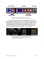
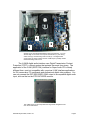
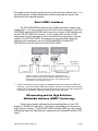
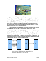
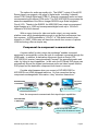
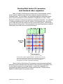
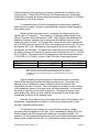
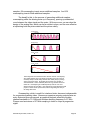
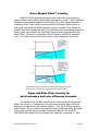
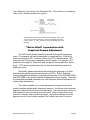
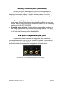
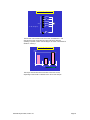
ES DVD Players Technical Background Version 4.0; August 8, 2005 Introduction Sony ES engineers are superbly educated, exceptionally well equipped and have ready access to world-leading in-house technologies. But these alone do not explain the soul of Sony's ES Series. You see, the creators of these components are motivated by their passion for music and movies. That's what drives them late into the night, seeking to control visual artifacts that most viewers will never notice. That's what takes them into the listening room, seeking to identify subtle sonic differences among various converters, capacitors and equipment interfaces. The result is an Elevated Standard in DVD/Super Audio CD/CD players. Presenting the DVP-NS9100ES and DVP-NS3100ES. Sony co-developed the Compact Disc, Super Audio CD and DVD. Our knowledge of these formats is encyclopedic. And Sony's expertise is clearly evident in these latest players. They represent superb craftsmanship and stateof-the-art electronic design. But there's more. The two models provide stunning, upscaled High Definition images, using the HDMI interface. And the NS9100ES is Sony's first DVD player to incorporate an i.LINK® (IEEE 1394) digital output for Super Audio CD signals1. i.LINK® and HDMI™ Digital Interfaces1................. Video Performance................................................. Audio Performance................................................. Construction & Design............................................ Features.................................................................. Specifications.......................................................... Page 3 Page 11 Page 28 Page 39 Page 42 Page 44 1. i.LINK is a trademark of Sony used only to designate that product contains an IEEE 1394 connector. All products with an IEEE 1394 connector may not communicate with each other. Please refer to the documentation that comes with the device having an i.LINK connector for information on compatibility, operating conditions and proper connection. ES DVD Players 2005, Version 4.0 Page 2 i.LINK® and HDMI™ Digital Interfaces In 1985, the engineers of Sony® ES surprised the world of high fidelity. The Sony CDP-650ES was the world's first CD transport with a digital output, enabling unheard-of sound quality and unprecedented flexibility in audio system configuration. Now such interfaces are taken for granted in high fidelity. In 1997, Sony staged another coup with the DCR-VX1000 Handycam® camcorder, the world's first video component to incorporate IEEE 1394, called the i.LINK® interface by Sony. Now such interfaces are found on almost every digital camcorder and millions of personal computers. In 2003, Sony took the i.LINK interface in an entirely new direction with the SCD-XA9000ES Super Audio CD/CD player. It was Sony's first to use the i.LINK interface to carry an uncompressed digital output for the Super Audio CD's Direct Stream Digital® signal. Today, Sony takes digital interfaces one step further. The DVPNS9100ES is Sony's first DVD/Super Audio CD/CD1 player to incorporate the i.LINK digital audio output. While both the NS9100ES and the NS3100ES incorporate a High Definition HDMI digital output that unifies both video and multi-channel audio! These are the most advanced digital interfaces Sony has ever built into a home A/V source component. i.LINK Digital Audio Output (NS9100ES) From the initial launch of Super Audio CD, the 1-bit DSD® pulse train was always converted to analog prior to output. This means that previous DVD players with Super Audio CD capability could only output the SA-CD sound in analog, not digital, even if the player included coaxial and optical digital outputs. 1. i.LINK is a trademark of Sony used only to designate that product contains an IEEE 1394 connector. All products with an IEEE 1394 connector may not communicate with each other. Please refer to the documentation that comes with the device having an i.LINK connector for information on compatibility, operating conditions and proper connection. ES DVD Players 2005, Version 4.0 Page 3 SA-CD D/A convert Speakers Amplifier SA-CD Player A/D convert Digital Signal DSP D/A convert LPF Volume Analog Power Amp Analog Signal Typical SA-CD reproduction involves numerous D/A and A/D conversions. The i.LINK digital connection can simplify the signal path. However, these analog connections can expose the Super Audio CD signal to repeated D/A and A/D conversions. The i.LINK® interface of the DVPNS9100ES overcomes this limitation. The i.LINK interface maintains the signal in the digital domain, protecting the music from repeated conversions. This i.LINK digital output is compatible with the i.LINK digital input on Sony's own STR-DA7100ES and the recent STR-DA9000ES. The i.LINK interface also enables a single digital cable to take the place of six analog cables. A portion of the DVP-NS9100ES back panel shows the multi-channel analog outputs (lower right), stereo analog outputs (center), optical and coaxial digital outputs for DVD and CD (upper left) and i.LINK digital output for Super Audio CD (lower left). ES DVD Players 2005, Version 4.0 Page 4 4 3 2 1 Internal layout of the DVP-NS9100ES as seen from the back. You can see the edge of one of the R-Core power transformers (1), the analog audio circuit (2), and the analog video circuits (3). The digital audio circuit board (4), which includes and the i.LINK output is partially hidden behind the analog video circuit. The i.LINK® digital audio interface uses Digital Transmission Content Protection (DTCP), a robust system that protects the music from piracy. The application of the i.LINK (IEEE 1394) interface for Super Audio CD is clearly different from—and not compatible with—previous i.LINK interface applications for DV camcorders, PC peripherals and professional digital video systems. You can only connect the DVP-NS9100ES i.LINK output to a compatible digital audio input, such as that on the STR-DA7100ES receiver. The i.LINK output circuit incorporates this Large Scale Integrated circuit from Texas Instruments. ES DVD Players 2005, Version 4.0 Page 5 High quality digital Audio Transmission System (HATS) The design of the i.LINK® interface is exceptional because communicating six streams of 2.8224 MHz digital samples raises extreme challenges. Conveying 1-bit signals at such high data rates and synchronizing the signals with the other component's master clock would normally expose the signal to the time-base errors called jitter. These errors translate directly into time-based distortion of the audio waveform. The connection from the DVP-NS9100ES to the STR-DA7100ES receiver overcomes this challenge with the High quality digital Audio Transmission System (HATS). HATS uses "command-based rate control of isochronous data flow" to solve the problem. The system incorporates three principal elements. 1. 2. 3. Variable-speed transmission from the player. Buffer memory in the receiver. Command signals from the receiver to the player, controlling transmission speed. The receiver continually monitors the amount of audio data in its buffer memory. When the buffer memory reaches its lower limit, the receiver commands the player to increase data transmission speed. When the buffer memory reaches its upper limit, the receiver commands the player to decrease transmission speed. And when the buffer memory is between the upper and lower limits, the receiver commands the player to transmit at normal speed. DVP-NS9100ES STR-DA7100ES With Sony® HATS, audio data flows from the player to the receiver's buffer memory, according to rate control commands from the receiver. Reproduction in the receiver achieves the full time base accuracy of the receiver's quartz crystal master clock. In this way, HATS makes it unnecessary to synchronize a jitter-prone signal with the receiver master clock. Instead, the buffer memory outputs a jitter- ES DVD Players 2005, Version 4.0 Page 6 free signal at the full quartz-crystal accuracy of the receiver's master clock. You get all the benefits of digital transmission, without exposing the signal to the potential for jitter-induced distortion. Dual i.LINK® interfaces The DVP-NS9100ES actually has two i.LINK® interfaces in daisy chain configuration.1 You can connect a second i.LINK source component to the DVPNS9100ES, while the NS9100ES itself connects to a single i.LINK interface port on the STR-DA7100ES A/V receiver. In this configuration, all three i.LINK components must be switched on for the second source component to transfer signals to the STR-DA7100ES. Performance is only guaranteed when the second source component is a Sony SCD-XA9000ES or another DVPNS9100ES and the A/V receiver is an STR-DA7100ES. DVP-NS9100ES SCD-XA9000ES or DVP-NS9100ES Thanks to the daisy chain architecture of the i.LINK interface, it is possible to connect components in different configurations. However, performance for the daisy chain on the right is only guaranteed when connecting the Sony equipment shown. 1. i.LINK is a trademark of Sony used only to designate that product contains an IEEE 1394 connector. All products with an IEEE 1394 connector may not communicate with each other. Please refer to the documentation that comes with the device having an i.LINK connector for information on compatibility, operating conditions and proper connection. HD upscaling and the High Definition Multimedia Interface (HDMI™) technology Today's home theater enthusiasts are increasingly likely to have "HD Ready" or "HD Built in" televisions. And they're just as likely to be starving for High Definition content. The DVP-NS9100ES and NS3100ES go a step toward fulfilling that need with High Definition upscaling of the Standard Definition DVD signal. ES DVD Players 2005, Version 4.0 Page 7 An HDMI™ plug and its corresponding jack. To begin with, many DVDs originate on film or progressive scanning video. These discs are encoded in 480p progressive scanning to deliver twice the vertical resolution as conventional 480i video. Sony's HD "upscaling" outputs this signal as 480p, 720p or 1080i High Definition via the High Definition Multimedia Interface (HDMI™) jack. You owe it to yourself to spend some time admiring the results. Slip in a top-quality DVD, and the upscaled image is sumptuous, rich and detailed. Even though this source material is Standard Definition, it comes amazingly close to the look of full High Definition. While 480p video is also available at the analog component video outputs, HD upscaling at 720p and 1080i is only available via the HDMI™ output. Established in September 2003, HDMI™ is an extension of the DVI digital interface. While DVI is limited to video only, HDMI™ can transmit uncompressed High Definition digital video and digital audio via a single cable. This greatly simplifies system set-up, replacing as many as ten analog and digital connections with just one cable! In addition to providing 480p, 720p or 1080i, the HDMI output of Sony® ES Series DVD players can support digital signals in both RGB component video and Y/Cb/Cr component video. Y Pb Pr DVD Player Left Right Center A/V Receiver or Television DVD Player HDMI A/V Receiver or Television Surround Right Surround Left Subwoofer Before HDMI technology (left), you needed nine cables to get component video and 5.1-channel analog audio from your DVD player and into your receiver. HDMI conveys both video and audio with full resolution and digital precision—all on a single cable! ES DVD Players 2005, Version 4.0 Page 8 The options for audio are equally rich. The HDMI™ output of Sony® ES Series players can support a full range of digital audio, including 2-channel stereo PCM, Dolby® Digital and DTS® 5.1-channel compressed audio and even uncompressed multi-channel PCM audio! The DVP-NS9100ES incorporates the awesome capabilities of the Silicon Images Sil9030 Large Scale Integrated Circuit (LSI). Thanks to the Sil9030, the NS9100ES can output uncompressed digital images up to 1080i and uncompressed digital audio up to 192 kHz/2channel or 96 kHz/8-channel! With so many choices for video and audio output, you may wonder whether users will be knowledgeable enough to get the best performance from their systems. Is RGB preferable to Y/Cb/Cr? Is 720p better suited to their television or 1080i? While users will have their choice from a menu of options, HDMI technology offers a simpler way. Component-to-component communication A system called “product unique key exchange” enables connected equipment to automatically confirm the type of component connected through the HDMI cable. In addition, a destination component (such as Sony's STRDA7100ES A/V receiver) can automatically "request" the appropriate audio and video, by listing its input capabilities. In this case, the ES Series DVD player can automatically choose the highest performance audio and video formats that the DVD player and the destination component both have in common! Consider what happens when you connect a DVP-NS9100ES or NS3100ES to an HDMI equipped television. On first connection the two components exchange basic information—they "introduce themselves." DVP-NS9100ES or NS3100ES Hi. I’m a DVD player. Television with HDMI input Hi. I’m a television. Next, the components communicate their input/output capabilities. DVP-NS9100ES or NS3100ES What is your input capability? ES DVD Players 2005, Version 4.0 Television with HDMI input I can accept 720p video and 2channel audio at 48 kHz and 16 bits. Page 9 Finally, the components agree on the highest available quality options for digital audio and video—and then automatically transfer content at that quality! DVP-NS9100ES or NS3100ES Television with HDMI input OK. I can output those signals. Thank you We've considered just a DVD player and a television. But the dynamic changes when you insert the Sony® STR-DA7100ES A/V receiver into the reproduction chain. In this case, the source component DVD player can only talk to the next component in the chain, the receiver. The receiver then communicates with the television and mediates the content exchange for the entire system. DVP-NS9100ES or NS3100ES Receiver with HDMI input & output Television with HDMI input Receiver, what is your input capability? Please note that some restrictions apply. • AC Power. All HDMI components must be switched on in order for the HDMI system to work. You can't use HDMI connections through the receiver if the receiver is switched off. • Anti-piracy. To prevent the piracy of very high quality digital signals, HDMI technology also incorporates a security method called High-bandwidth Digital Content Protection (HDCP). This encrypts the signal so that only authorized devices can decode the data into pictures and sound. The HDMI connection is for playback only, meaning that content distributed via HDMI cable cannot be recorded. • Super Audio CD. As of January 2005, standards for sending Super Audio CD sound over HDMI cables had not been established. For this reason, Super Audio CD sound is not available over the HDMI outputs of the DVPNS9100ES and NS3100ES. ES DVD Players 2005, Version 4.0 Page 10 Video Performance Precision Cinema Progressive™ circuitry The purpose of today's high-end home theater systems is to recreate the look and sound of the movie theater. This includes the vivid detail and seamless coherence of the film frame. A crucial technology for achieving this goal is DVDVideo playback with progressive scanning, "480P" output. This works with many of today's "HD capable" and "HD monitor" televisions, which offer 480P inputs. For example, Sony markets this capability as a Hi-Scan 1080i™ television. In this context, 480P outputs have been promoted as a must-have feature in DVD players. However, there continue to be important differences in how DVD players generate the 480P signal. The DVP-NS9100ES and NS3100ES have Sony's Precision Cinema Progressive system, a comprehensive approach that incorporates two significant circuits to deliver a picture that comes closer than ever to the original movie theater experience. Sony's Pixel-by-Pixel Active interlace-to-progressive (I/P) conversion ensures maximum resolution, while Sony's Vertical Edge Compensation reduces artifacts along the edges of objects in the scene. Pixel-by-Pixel Active I/P Conversion Interlace-to-Progressive (I/P) conversion is a potentially tricky process. The solutions range from inexpensive and simplistic to sophisticated Hollywood postproduction systems that require powerful computation. Optimum I/P conversion is challenging because there are so many different types of content: 1. Material originated on film (or on 24-frame progressive digital systems, which in this context behave just like film). 2. Material originated on film and recorded onto DVD-R/RW or DVD+R/RW. 3. Material that quickly intercuts video and film-originated footage. 4. Material that has film and video showing at the same time. 5. Material originated on interlaced video. These different types of DVD material place different demands on the I/P converter. A conversion strategy optimized for material originally shot on film will not get the best results for material originally shot on interlaced video, and vice versa. ES DVD Players 2005, Version 4.0 Page 11 The mathematical algorithms of Sony's Pixel-by-Pixel Active I/P conversion have been committed to silicon in this Large Scale Integrated circuit (LSI), the Sony CXD9866R. Sony solves the problem with Pixel-by-Pixel Active I/P conversion that includes built-in motion detection. The system automatically recognizes each type of material and applies the appropriate processing. This enables us to generate the ideal progressive scanning output for each type of DVD source. • Film originated material. For footage originally shot on 24-frames per second film and 24-frame progressive digital cameras, simplistic solutions like "frame memory" can end up creating motion artifacts that mar the final result. These appear as zipper-like patterns on the left and right edges of moving objects. The Sony® system automatically and flawlessly detects the 3-2 cadence and performs full "3-2 reverse conversion," which maintains the integrity of the original film frames. Mismatched film frames are never "forcefit" into a single video frame. The system adds no motion blurring. You'll enjoy twice the vertical resolution of conventional interlace video, for an experience that's less like watching television and more like watching film. • Film originated material on a DVD-R/RW or DVD+R/RW. DVD recorders complicate the I/P conversion processes, because these recorders capture everything as interlaced video. That means movies, even if they were originally shot on film, are recorded as 30 frames per second interlaced, not 24 frames per second progressive. There are none of the usual First Field Repeat Flags (FFRFs), leaving many DVD players unable to guess at the original frame structure. In this case, conventional 3-2 reverse conversion will not work, but Sony's Pixel-by-Pixel Active I/P conversion will. Thanks to builtin motion detection, the Sony system does not depend on FFRFs. So you get accurate reproduction on DVD-R/RW and DVD+R/RW discs. • Film material intercut with video material. Sony's Pixel-by-Pixel Active I/P conversion applies appropriate processing for film elements and interlaced video elements, even when they alternate in rapid-fire sequence, as they might during the "making of" documentary on a movie DVD. The Sony system instantly recognizes the characteristics and film and video and automatically applies the correct processing for each. ES DVD Players 2005, Version 4.0 Page 12 • Film and video material shown simultaneously. The Sony® system performs beautifully even when film and video appear on-screen at the same time, for example, when video-originated subtitles are superimposed over a film-originated scene. Because the Sony system analyzes each individual pixel, it can switch processing modes anywhere—even in the middle of a scanning line! In contrast, conventional systems need to wait until the end of the field before switching between film and video modes. • Interlaced video. Shooting on interlaced video means capturing a new field of 240 interlaced scanning lines every 1/60 second. When subjects are moving, there can be significant differences from each field to the next. It's a far cry from film 24 frame progressive origination, where the subjects move each 1/24 second. Combining two video-originated fields of 240 interlaced scanning lines into one frame of 480 progressive scanning lines is no simple task. For this reason, Sony's Pixel-by-Pixel Active I/P conversion applies special processing for video originated material. In addition, these Sony ES Series DVD players enable you to adjust the threshold of film and video detection. So you can optimize the I/P conversion for the specific DVD you're watching. You get I/P conversion that's not only amazingly smooth, but also exquisitely tuned to the individual needs of each DVD. When you're done watching, the players can store the setting in memory for up to 400 discs. So each time you play that title, you'll automatically get just the right conversion! An on-screen display enables you to adjust the threshold of film and video detection for each individual disc. Sony players can even store your setting for use the next time you play that title! ES DVD Players 2005, Version 4.0 Page 13 Pixel-by-Pixel Active I/P conversion and interlaced video origination Many of today's DVDs feature concert videos, documentaries, current events, sports, nature footage and other subjects originally captured on interlaced video. For this reason, any high-end progressive scanning system must solve the problem of motion artifacts for footage shot on video. Video based I/P conversion creates new pixels from existing information. For example, to enable progressive scan output for a field of odd scanning lines, the player must create the pixels that compose all the even scanning lines. Unfortunately, this can result in motion blur. Horizontal lines in the scene can flicker on and off. Other areas can suffer from an unnatural shimmer. Scanning lines EVEN future ODD current EVEN Past 1 ODD Past 2 EVEN Past 3 Time sequence I/P conversion of video originated material. The red pixel, on an even scanning line needs to be created for the current field of odd scanning lines. If not done properly, this can result in zipper-like edges on moving objects, line flicker and unnatural shimmering. Sony's Pixel-by-Pixel Active I/P conversion overcomes these problems with built-in motion detection and two distinct video conversion algorithms: one for still objects, another for moving objects. As with film origination, the algorithms are applied separately for each individual pixel. So both can be applied to different parts of any given scene! ES DVD Players 2005, Version 4.0 Page 14 Still Processing Moving Processing Still Part Moving Part The typical interlaced video frame includes both still and moving pixels. Sony Pixel-by-Pixel Active I/P conversion applies separate processing for each. • Pixels for still objects are the easiest to handle. When objects are not moving, the player can simply use the corresponding pixel from the previous field. Because there is no motion, these pixels will match perfectly with the current field, creating a seamless progressive scan output. Scanning lines EVEN future ODD current EVEN Past 1 ODD Past 2 EVEN Past 3 Time sequence STILL PIXEL PROCESSING Pixels for still objects are simply created from the corresponding pixel in the previous field. • Pixels for moving objects are created by composing pixels from scanning lines immediately above and below within the same field. Because all information comes from the same 1/60-second slice of time, this suppresses motion artifacts. While this process does not result in the full improvement in vertical resolution, the human eye is less sensitive to detail in moving objects. So the overall effect is a stunning improvement in image detail, clarity and solidity. ES DVD Players 2005, Version 4.0 Page 15 Scanning lines EVEN future ODD current EVEN Past 1 ODD Past 2 EVEN Past 3 Time sequence MOVING PIXEL PROCESSING Pixels for moving objects are created by composing pixels from the scanning lines immediately above and below in the same field. This minimizes motion blur. Thanks to Sony's flexible approach, still backgrounds are impressively sharp and detailed, while moving objects in the same scene are free from motion artifacts. You'll see more consistent, more satisfying, more seamless 480P output with a wider variety of discs. The visibility of scanning lines is all but eliminated. Connect a 480P-compatible television, monitor or projector and prepare to be amazed. Just as you can adjust the threshold of film/video detection, you can optimize the still/motion detection for the specific requirements of the DVD you're watching. As before, the players can memorize your Still/Motion threshold for up to 400 discs. So each time you play a title, you'll automatically get just the right conversion! You can adjust the Still/Motion detection threshold with this on-screen display. As before, your setting for each disc can be stored in memory. Vertical Edge Compensation As we've seen, Sony's Pixel-by-Pixel Active I/P conversion of video sources suppresses the zipper-like effect that can occur when moving areas of two interlaced fields are combined in the same progressive frame. It's a major step forward in picture quality. But there a second, less obvious artifact that can ES DVD Players 2005, Version 4.0 Page 16 occur in part of the video image part of the time. Most people would not notice the artifact without being told when and where to watch for it. But Sony's program for these ES components required us to address even subtle distortions. The problem is jaggedness in the edges that separate areas of the scene, especially when the edges are straight lines, when they're diagonal and when there's a big difference in contrast between the areas they separate. Rooflines, car hoods, venetian blinds and other lines in the scene can appear with unwanted stair steps not in the original program. Sony's Vertical Edge Compensation controls this artifact. Pixels on the line above Pixel being created Pixels on the line below Sony's Vertical Edge Compensation uses a broad range of pixels on the lines immediately above and below to calculate a pixel on moving edges. This controls the jaggedness that can sometimes distort edges in the video picture. Vertical Edge Compensation uses the built-in motion detection to judge motion at the pixel level and to detect edges. When the circuit detects an edge, it refers to other edges within the field. The circuit then assembles data from a broad range of pixels on the lines immediately above and below to calculate the new pixel. This smoothes out the stair steps and results in consistent, naturallooking lines throughout the picture. It's just one more way that Sony raises the standard in DVD-Video picture quality. Precision Cinema Progressive™ circuitry in action We've devoted seven pages to Pixel-by-Pixel I/P Conversion and Vertical Edge Compensation—the technologies behind Sony's Precision Cinema Progressive circuitry. But while the technology is complex, the benefit only takes a moment to appreciate. Start with a high-quality DVD that you know well. Using HDMI or Y/Pb/Pr component video, connect the Sony® DVD player to a great High Definition or HD-capable television, monitor or projector. Then watch. The original frames retain their integrity, even if they were originally shot on film or 24P progressive digital. You'll see full performance for every part of the picture, whether still or moving. The vertical edges on objects in your picture retain all their clarity, even when the objects are in motion. The horizontal edges are clean and clear, without the obvious stair steps or jaggedness. You'll ES DVD Players 2005, Version 4.0 Page 17 approach the full glory of High Definition picture quality—from today's standard DVDs. 14-bit D/A Conversion (NS9100ES) The binary word length used in video digital-to-analog (D/A) conversion helps determine the gray scale performance of the picture. This can be seen, for example, in the play of light across the face of an actress, as the light of a candle falls off into shadow. Longer word lengths contribute to smoother, more realistic transitions from dark to light. Starting with the DVP-S7000, Sony led the way with 10-bit video digital-toanalog conversion. The DVP-NS900V raised the performance to 12-bit conversion, producing four times the grayscale levels. The DVP-NS999ES incorporated the Analog Devices ADV7304A, a 14-bit video D/A converter. Now the DVP-NS9100ES incorporates the Analog Devices ADV7324, a refined 14-bit converter. This produces four times the grayscale levels of common 12-bit designs—and a total of 16 times as many as earlier, 10-bit designs. The 14-bit video D/A converter also includes the video encoder and processing for Macrovision™ Copy Protection. Sony applies the 14-bit process both to DVD's luminance (Y) black-andwhite channel and to DVD's two color difference channels (PB and PR). So you get more accurate rendition of colors from the deepest black to the brightest highlights. 216 MHz D/A converter oversampling In DVD-Video playback, the ultimate in picture detail comes into direct conflict with the ultimate in picture clarity. Detail is a function of the video "bandwidth" or "frequency response." The highest resolution details occupy the highest video frequencies. Clarity is a function of video "noise." In the worst case, noise appears as "snow" or flecks and specks of unwanted color. In more ES DVD Players 2005, Version 4.0 Page 18 subtle examples, noise appears as a texture or graininess not present in the original picture. These Sony® ES Series DVD players achieve a remarkable combination of superb fine picture detail and excellent clarity, thanks to 216 MHz oversampling in the D/A converter. To understand how 216 MHz oversampling can have such a powerful effect on picture quality, it helps to understand the concepts of digital sampling and aliasing noise. Digital recording systems work by "sampling" the original source at a specific rate, or "frequency." The frequency of sampling is determined by the Nyquist Theorem, which dates back to 1928. Harry Nyquist calculated that the sampling frequency needed to be at least twice the highest frequency in the signal you need to record. For Compact Disc, which records audio frequencies up to 20,000 cycles per second (20 kHz), the sampling frequency is 44,100 times per second (44.1 kHz). Because the video signal is much more complex, the frequencies are far higher. To capture the exceptional fine picture detail of DVD, the black-and-white or "luminance" channel records frequencies out to 6,750,000 Hz (6.75 MHz). This means that DVD samples the video luminance channel at 13,500,000 Hz (13.5 MHz), as part of the DVD-Video format specification. Channel Bandwidth 20,000 Hz 6,750,000 Hz CD Audio DVD-Video Sampling Frequency 44,100 Hz 13,500,000 Hz Digital recording systems sample the analog input signal at a specific rate or frequency at least twice the highest frequency of the channel. For DVD-Video, the sampling frequency is 13,500,000 times per second (13.5 MHz). Nyquist sampling only works properly if the analog output is carefully filtered of the aliasing noise that the digital process incurs. Fortunately, the aliasing noise is consistently higher in frequency than the highest video frequencies we want to recover. The noise appears in clusters at each multiple of the sampling frequency, plus and minus the video bandwidth. Unfortunately, the noise is very close to the video frequencies. The player must use a very steep analog filter, which must be carefully constructed to pass all the video frequencies and block all the aliasing noise. Normally, even slight errors in the analog filter could cut the highest video frequencies—degrading picture detail—or allow some aliasing noise to pass through—degrading picture clarity. The solution to this problem is to run the A/D converter at a higher frequency than the samples on the disc. This "oversampling" design fills in the blanks between the DVD samples with additional, calculated samples. For example, 2X oversampling calculates and inserts one additional sample between each original sample from the disc. 4X oversampling inserts three additional ES DVD Players 2005, Version 4.0 Page 19 samples. 8X oversampling inserts seven additional samples. And 16X oversampling inserts fifteen additional samples. The benefit is this: in the process of generating additional samples, oversampling shifts the aliasing noise up in frequency, opening up substantial room between the video signal and the noise. With more room, we can relax the design of the analog filter, which can be far milder in slope, and far more effective at optimizing both the picture detail and the picture clarity. 27 MHz-Sampling Analog-Filter Video Signal Noise 27 Noise 54 Noise Noise Noise Noise 108 Noise Noise 216 54 MHz-Sampling Video Signal 27 Noise Noise Noise Noise 54 108 216 Noise Noise 108 216 108 MHz-Sampling Video Signal 27 54 216 MHz-Sampling Video Signal Noise 27 54 108 216 These diagrams show interlaced video and the need for oversampling. At 27 MHz sampling (top), the design of the filter (red curve) must be extremely steep to avoid cutting into the video detail (blue) or passing some of the noise (pink). At 54 MHz (second from top), the filter is somewhat better. And at 108 MHz (third from top), the filter becomes better still. Oversampling at 216 MHz (bottom) leads to a far more effective analog low-pass filter. This enables the Sony® ES Series DVD players to deliver all the picture detail, without degrading the clarity of the image with noise. Oversampling, which is useful for interlaced video, becomes indispensable for progressive scanning video. Because progressive scanning outputs twice as many horizontal lines per second, progressive playback effectively doubles channel bandwidth to 13.5 MHz and doubles sampling frequency to 27 MHz. Players need a minimum of 27 MHz sampling in order to output a progressive signal. ES DVD Players 2005, Version 4.0 Page 20 DVD-Video Interlaced Playback DVD-Video Progressive Playback Luminance Channel (Y) Bandwidth 6.75 MHz Luminance Channel (Y) Sampling Frequency 13.5 MHz 13.5 MHz, effective 27 MHz, effective Progressive scanning effectively doubles both the video bandwidth and the sampling frequency. While only the luminance (Y) channel is shown here, this doubling also occurs for the two color difference channels (PB and PR). 27 MHz-Sampling Loss Video Signal Analog-Filter Noise Noise Noise Noise Noise Noise Noise Noise Including Noise 27 54 108 216 54 MHz-Sampling Video Signal 27 Noise Noise Noise Noise 54 108 216 Noise Noise 108 216 108 MHz-Sampling Video Signal 27 54 216 MHz-Sampling Video Signal Noise 27 54 108 216 At 27 MHz sampling (top), the design of the filter (red curve) is extremely challenging for progressive scanning. The filter either cuts into the video detail (blue) or passes some of the noise (pink). Oversampling at the 216 MHz frequency of the Sony® ES Series DVD players makes a huge difference. Oversampling has been used successfully in CD players for decades. And while the video equivalent is harder to achieve, the effect is the same. The D/A converter of the DVP-NS9100ES and NS3100ES shift the sampling frequency from the standard 13.5 MHz to 216 MHz. For progressive scan playback, that's 8x oversampling. For interlaced playback, it's a whopping 16x oversampling. This oversampling is the most powerful that Sony has ever built into a DVD player. You get superb clarity with the effective suppression of video noise, while enjoying the full video bandwidth for breathtaking picture detail. ES DVD Players 2005, Version 4.0 Page 21 Noise Shaped Video™ circuitry While 216 MHz sampling deals with noise outside the video frequency range, another circuit reduces noise within the frequency range. That's important because the perceived transparency and depth of the video image depends on controlling noise. Sony's D/A converter uses Noise Shaped Video circuitry to shift noise from inside the visible frequency range to outside. Even though the overall noise level remains the same, the perceived noise is dramatically reduced. What's more, once shifted, the out-of-band noise is further suppressed by the analog filter. The result is reproduction without flecks or specks of unwanted color. You'll see a video picture that's vibrant, deep, transparent and clean. Noise Shaped Video and the higher 216 MHz sampling frequency work together to cut video noise for improved transparency and clarity. Super Sub Alias Filter circuitry for both luminance and color difference channels. The benefit of the 216 MHz sampling rate is delivered by the Super Sub Alias Filter circuits. In comparison to most previous designs, these filters are now far more effective for two powerful reasons. First, the 216 MHz sampling rate is higher. Second, while some previous designs deployed Super Sub Alias Filter circuitry on the black-and-white (luminance) channel only, the DVPNS9100ES uses these filters on all three video channels: luminance (Y), blue ES DVD Players 2005, Version 4.0 Page 22 color difference (PB) and red color difference (PR). This results in a consistently clean, clear, vibrantly detailed color picture. The typical filter leaves traces of the clusters of aliasing noise, which look like lumps in the top diagram. Super Sub Sampling Alias Filter circuits on the Y, PB and PR channels control this aliasing noise more effectively. "Below Black" reproduction with Graphical Gamma Adjustment The DVD format dictates specific quantization for specific brightness levels. For example, full black corresponds to a quantization of 16 while full white corresponds to 235. However, direct-view CRTs, plasma panels, CRT projectors and LCD projectors each have specific needs. For example, LCD projectors are subject to "black float" and can benefit from a calibration "below black." CRT direct view televisions tend to lose dark detail when viewed in brightly-lit rooms. Historically, gamma adjustment has matched the grayscale of a video camera to the general transfer characteristics of CRTs. Sony's Graphical Gamma Adjustment matches the grayscale performance of the DVP-NS9100ES and NS3100ES to the specific transfer characteristics of your display. Used with a commercially available calibration disc, the Graphical Gamma Adjustment can achieve ideal reproduction. The system enables you to make adjustments to gamma much like a graphic equalizer adjusts audio frequency response. As with an audio equalizer, aggressive adjustment can yield unnatural results. The controls are best used to make gamma curves that are smooth and subtle. Sony's control offers eight points of correction, each with 8-bit precision. And you can always return the gamma controls to the industry-standard "flat" state at the touch of a button. ES DVD Players 2005, Version 4.0 Page 23 Graphical Gamma adjustment is like an eight-band graphic equalizer for grayscale and black level. Video Equalizer Sony's Video Equalizer enables you to fine-tune the picture quality of each disc you watch. You can adjust Picture, Brightness, Color, Hue and Chroma Delay in addition to Graphical Gamma Adjustment. And once you've optimized the picture for a particular disc, these ES Series DVD players can commit your settings to memory for up to 400 discs. Separate analog video circuit board with separate power supply The digital and control circuits of any DVD player generate high-frequency radiation that can affect other circuits in the chassis. This noise can potentially impair low level analog signals. To prevent any cross-interference, Sony carefully separates the digital circuits from the analog circuits, mounting them on separate circuit boards. This maintains the purity of the analog signal to achieve consistently clean video images. ES DVD Players 2005, Version 4.0 Page 24 To maintain the purity of the signal, Sony places the analog video circuitry on a separate board, driven by its own power supply. Because digital noise can corrupt the DC voltage, the power supply is another potential path of interference. That's why early on, Sony recognized the advantage of giving the analog circuit block its own series power supply. This ensures power that's both abundant and clean. Video Shield Plate (NS9100ES) DVD players process analog audio, analog video and digital signals in close proximity, opening up the possibility of signal radiation and interference even between circuit boards. To prevent even slight traces of interference, the DVP-NS9100ES incorporates a shield underneath the analog video circuit board. This protects the analog video from radiated interference from the digital video board. It also limits the interference between analog video and the digital audio board, which is located close by. To minimize signal interference, the DVP-NS9100ES has a shield plate fitted to the underside of the analog video circuit board. ES DVD Players 2005, Version 4.0 Page 25 High speed video buffer amplifiers (NS9100ES) If your television accepts an HDMI™ cable, you can enjoy a fabulous alldigital video connection. If not, you'll be happy to note that Sony® engineers are passionate about achieving exceptional performance from analog video connections. For example, the long analog cable runs found in many home theater installations can be highly capacitive. This tends to degrade the video signal, softening the picture and limiting the video bandwidth. To counter this possibility, the DVP-NS9100ES incorporates high-speed video buffer amplifiers. High slew-rate op amps handle large loads with very low overshoot. You get a powerful driving force for the video signals, even over long cable runs. As a result, the video signal delivered to the television has extremely low levels of noise, differential gain and differential phase. Analog Video Board Component Low pass filter For Progressive (Component) Cr Cb MAIN Board AV Decoder STE5588CVB IP Converter CXD9866R Low pass filter For Interlace (CVBS,S-Video) 16M SDRAM RCA OUT (525i/p) Y VIDEO Encoder ADV7324 Y(S-Video) S-Video C(S-Video) CVBS CVBS Buffer Op-Amp AD8058 X 6 Power Supply For Analog Video Circuit +5V -5V Block diagram of the DVP-NS9100ES video circuit. You can see the separate digital circuit board (left) and analog circuit board (right). At center, you can see the nine channels of low-pass filtering. On the right are the video buffer op amps. Output Capacitor-Less (OCL) coupling In typical audio and video design, an output capacitor prevents the accidental passing of DC offset voltage from one component to the next. However, the mere presence of the output capacitor can affect the video frequency response and literally tinge the television picture with unwanted shading. And these effects can't be corrected by your television's picture controls. Sony's answer is a rigorous design that controls DC offset voltages from the start. You get reliable operation without performance-robbing output capacitors. ES DVD Players 2005, Version 4.0 Page 26 Carefully selected parts (NS9100ES) More than a labor of technology, the DVP-NS9100ES represents the enthusiasm that Sony® engineers share with high-end videophiles. That's why the player incorporates a variety of carefully selected resistors, inductors, semiconductors and capacitors. Each plays a specific role in maximizing video performance. Low Distortion Film Capacitors. While electrolytic capacitors are suited to power supply filtering, film capacitors are especially proficient for sound and picture. Many of these low-distortion capacitors contribute to the outstanding performance of the DVP-NS9100ES. Oversized output resistors. Output resistors determine the impedance of the analog output circuits. Most designers avoid large resistors. But Sony incorporates large resistors of uncommonly tight tolerances. This contributes to the high slew rates required for wideband video. Wide pitch component output jacks Sony engineers even anticipated the high-grade output cables that videophiles are likely to plug into the ES Series DVD players. For this reason, Sony deliberately spaced the Y/PB/PR output jacks further apart than common practice, the better to accommodate heavy-gauge cables and plugs! The spacing or "pitch" between the component video output jacks is wider than usual, to accommodate heavy-gauge cables and plugs. ES DVD Players 2005, Version 4.0 Page 27 Audio Performance In addition to DVD-Video and Compact Discs, these ES Series DVD players also reproduce sumptuous high-resolution audio: both stereo and multichannel Super Audio CD music. You'll hear the inner detail of choral ensembles. The reverberation trailing from a guitar chord. And the acoustic space surrounding the instruments. With Super Audio CD, you hear every nuance of sound reproduced with incredible ease and clarity. Multi-channel Super Audio CD playback The ES Series DVD players take full advantage of the latest generation of multi-channel Super Audio CD music. Multi-channel Super Audio CD gives producers the ability to capture the precise ambience and reverberation that give any concert hall, jazz club or recording studio its characteristic "sound." Multichannel Super Audio CD doesn't just bring the performer to your room; it sounds as if you have entered the performer's space. The result can be overwhelming. By combining this fully dimensional soundstage with the uncanny clarity of DSD® technology, these players offer music reproduction that's nothing short of brilliant. DSD® decoder LSI The Super Audio CD’s 1-bit signal is processed and decoded by Sony's DSD decoder LSI. This integrated circuit makes intelligent decisions regarding processing of the incoming data to form the 1-bit audio signal. The LSI first reads the Watermark—a feature protecting Super Audio CDs from illegal copying—and then decodes the incoming data. The LSI uses internal memory to take data that's output intermittently from the disc, rearrange it and order it into continuous 1-bit audio streams. This LSI also reads sub code data such as the Table of Contents, track number, track time, and text data. Audio Technology for Analog Outputs While the provision of an i.LINK® digital interface for Super Audio CD signals is a technological tour de force, compatible equipment is just beginning to become available. Clearly, many owners of the DVP-NS9100ES will be enjoying Super Audio CD through analog outputs. For this reason, Sony has developed sophisticated technology to provide an analog output of superlative linearity, with extraordinary freedom from noise, interference and jitter-induced distortion. The result is unsurpassed music reproduction, no matter which outputs you use. ES DVD Players 2005, Version 4.0 Page 28 Speaker Time Alignment For optimum playback, the mastering engineers who create CDs need to anticipate the speaker configuration over which the music will be reproduced. In stereo, that configuration is simple: two identical speakers ideally set an equal distance from the listener. In a multi-channel sound, the ideal is slightly more complex. Multi-channel Super Audio CD is designed to conform to an international standard, called ITU-R. This envisions that the listener sits in the exact center of a circle of five identical speakers, with each speaker occupying a specified position in the circle. (For the Low Frequency Effects or LFE channel, the subwoofer can be flexibly placed outside the circle.) The ITU-R circle makes a great reference for studio engineers. But few home environments can accommodate exactly this setup. Even if you did have five identical speakers all the way around, the rectangular shape of most rooms would make it difficult to place all five speakers at equal distance from the listening position. Center Right Left LF 30° 110° Reference Left surround Right surround Mastering for Super Audio CD multi-channel sound assumes that speakers will be placed according to the international ITU-R standard. To resolve the problem, Sony provides a special Digital Signal Processor (DSP) that adjusts the arrival time of each channel with delay in 900microsecond increments. Because most people can't make the mental leap from microseconds to speaker distance, Sony calibrates the delay as distance, in 30cm (1-foot) increments. Each 900 microseconds of delay "moves" a speaker back 30 cm (1 foot). In this way, Speaker Time Alignment adjusts the "virtual position" of each speaker, enabling you to synchronize the arrival time of sound for all five speakers. You can even change the perceived distance of the subwoofer in relation to the other speakers. With Speaker Time Alignment, you'll experience multi-channel sound as it was meant to be heard. You'll get the effect of correct speaker placement, even if your actual placement is far less than correct! ES DVD Players 2005, Version 4.0 Page 29 Incidentally, this adjustment is not duplicated on most A/V receivers. Some receivers can adjust for speaker distance on the multi-channel signals that are decoded in the receiver itself. But most receivers offer no such adjustment for the 5.1-channel analog inputs you may be using to enjoy multi-channel Super Audio CD. A/V Sync Today's advanced televisions and video projectors often incorporate sophisticated video signal processing to optimize the image quality. Often, these circuits require buffer memories that result in a slight delay of the video signal. Unfortunately, this can result in a mismatch, where the television picture lags behind the sound from the speakers by some fraction of a second. As you can imagine, the effect can be unnatural and annoying. That's why Sony offers another Digital Signal Processing function: AV Sync. This enables you to correct time misalignments between the audio and video signals by up to 120 milliseconds, in 10 millisecond increments. Sony brings your television and your home theater speakers back into alignment. A/V Sync achieves identical results on stereo, 5.1-channel and even digital audio outputs. Separate speaker settings Unlike previous models, the DVP-NS9100ES and NS3100 also provide speaker size and location settings for Super Audio CD playback that are separate from the settings you make for DVD-Video and other formats. Super Audio D/A Converter (SA DAC) If you're using the DVP-NS9100ES with an amplifier that does not have an i.LINK® interface of if you're enjoying the NS3100ES, you won't be listening to Super Audio CDs via digital output. In this case, the player's on-board D/A converters will exert a pivotal influence on sound quality. Multi-channel Super Audio CDs present the player with six separate channels—all recorded with exactly the same superb quality as two-channel Super Audio CD. That's why the Sony® ES Series DVD players incorporate six channels of Sony's Super Audio D/A Converter (SA DAC). The circuit delivers superlative performance for multi-channel SA-CD, two-channel SA-CD and CD reproduction. ES DVD Players 2005, Version 4.0 Page 30 CD 16 bit/1 fs 24 bit/8 fs 8x Oversampling digital filter Noise shaper 1 bit/64 fs Multi level D/A converter SACD 1 bit/64 fs DSD filter 1 bit/64 fs Sony's Super Audio D/A Converter (SA DAC) does an equally superb job on Compact Disc signals (top) and SA-CD signals (bottom). The converter consists of a single integrated circuit that contains four significant circuits: 1. 8x oversampling digital filter for CD. Ensures accurate phase linearity and low noise. 2. Noise shaper for CD to further suppress audible noise. The noise shaper also puts out a 1-bit signal at 64 times the CD sampling frequency (1-bit/64 fs). Sixty-four times 44.1 kHz equals 2.8224 MHz, the same sampling frequency as Super Audio CD. In this way, the SA DAC presents both CD and SA-CD signals to the final converter stage in the identical 1-bit/64 fs form. 3. DSD® filter for SA-CD, a digital filter that removes unwanted super high frequency noise by computing raw 1-bit digital data. By reducing noise in the digital domain, the DSD filter reduces the burden on analog filters and contributes to the uniformity among channels. 4. Multi-level DAC for both SA-CD and CD is a breakthrough design that combines the best attributes of 1-bit converters and multi-bit converters for sound that is exceptionally transparent, against a background that is phenomenally free from noise. Sony's multi-level digital-to-analog conversion is a significant step forward in audio technology. To appreciate the advance, it's important to understand three types of digital-to-analog converters: multi-bit, 1-bit and multi-level. ES DVD Players 2005, Version 4.0 Page 31 Multi Multi level level D/A D/A conversion conversion LSB 1 2 4 8 + 16 … MSB 32,768 Multi-bit D/A conversion in a typical early CD player employed 16 switches, corresponding to the 16 bits of the CD sample. Each switch produced a different level of current, according to the significance of the bit. In the 1980s, the overwhelming majority of CD players used multi-bit Digital-to-Analog converters (DACs). Also called "ladder type" or "resistor ladder" converters, these designs typically used one resistor switch for each digital bit in the sample. The value of the resistor controlled the amount of current that flowed when the switch was On. Each switch produced current proportionate to the value of the corresponding bit. For example, the current for the Least Significant Bit (LSB) was 1, the next bit was 2, the next 4, the next 16 and so on up to the 16th or Most Significant Bit (MSB), which had a value of 32,768. While these converters could offer superb dynamic range, they were susceptible to a distortion called nonlinearity. For any given output level, the combination of switches set On and Off would always be the same. In this way, if a switch's current source had an error, that error would always be reflected in the output level and the linearity would always be spoiled in exactly the same way. This problem of errors and nonlinearity was especially important in the MSB, because the MSB is so big in comparison to the other bits (for example, 32,768 times the current of the LSB). So even slight errors in the MSB could overwhelm the value of the smaller bits, distorting the musical signal at the zero cross, where the binary digits flip from 1111111111111111 to 0000000000000000. These errors are generally masked by the music, when it is loud. But when the music is soft, this problem of "low-level nonlinearity" can impart a grit or hardness to the music that university researchers found to be audible. For this reason, technologists developed 1-bit D/A converters that bypassed the problem completely. Significant among these 1-bit designs was Sony's own High Density Linear Converter™ circuit, which made its debut on the ES DVD Players 2005, Version 4.0 Page 32 landmark CDP-X77ES in 1990 and has since been followed by Sony's Current Pulse 1-bit converter. Like other 1-bit converters, these Sony® designs overcame the problem of zero-cross distortion, achieving superb low-level linearity for excellent sound, even during quiet passages and the reverberant tails at the end of musical notes. 11 bit bit D/A D/A conversion conversion (Current (Current pulse) pulse) On/off 1 value 1 0 on off on off on off variable 1 /64fs 1 /64fs 1 /64fs time PWM (PULSE WIDTH MUDULATION) The principle of 1-bit D/A conversion. In order to reproduce Super Audio CD, Pulse Width Modulation must operate at a higher frequency than the SA-CD sampling frequency of 64 fs (equal to 2.8224 MHz). These 1-bit converters performed beautifully and dominated CD player design throughout the 1990s. However, in order to avoid the influence of jitter, to maintain linearity in the time axis, 1-bit converters need to be driven by a highly precise clock. And Super Audio CD makes this demand for precise timing even more stringent. Super Audio CD uses an extremely high sampling rate of 2,822,400 samples per second—2.8224 MHz. Many 1-bit converters employ Pulse Width Modulation, in which the converter modulates the output by creating longer or shorter pulses. Unfortunately, this requires a D/A converter clock frequency substantially higher than 2.8224 MHz. Because it's extremely difficult to maintain clock precision at such high frequencies, the signal is exposed to time-axis errors—jitter—which pass directly into the analog audio waveform, causing subtle distortion. Such distortion was not acceptable for the design program of the ES Series DVD players. That's why Sony® ES engineers endowed the SA DAC with Sony's multi-level D/A conversion. Unlike the multi-bit conversion used at the dawn of the digital age, multi-level conversion exhibits superb low-level linearity. And unlike the 1-bit conversion, multi-level conversion is remarkably free from jitter and jitter-induced distortion. You get the best of both worlds. The multi-level D/A system has multiple switches controlling multiple current sources—in effect a number of 1-bit digital-to-analog converters operating in parallel. The analog output is created by summing all the current sources. Unlike 1-bit DACs, output is expressed not by the pulse width but the number of the current sources. This reduces the clock frequency, reducing the influence of clock jitter and reducing the radiation of noise into nearby circuits. ES DVD Players 2005, Version 4.0 Page 33 Multi Multi level level D/A D/A conversion conversion 1 1 1 N N= 64 (for spec 1) + 1 1 … 1 The SA DAC uses multi-level D/A conversion, illustrated here. Like multi-bit conversion, the multi-level system uses many switches operating in parallel. Unlike multi-bit designs, the value of all switches is identical—a binary 1. Multi Multi level level D/A D/A conversion conversion Output 64 0 1 / 64 fs 1 / 64 fs 1 / 64 fs time The output of the multi level D/A converter varies from 0 to 64, depending on the number of switches set to On for each sample. ES DVD Players 2005, Version 4.0 Page 34 Multi Multi level level D/A D/A conversion conversion Multi-Bit Multi-Bit D/A D/A conversion conversion 1 1 1 A 1 A 1 B 2 B 2 C D + 4 C 1 1 4 Output =2 1 1 1 1 1 1 Output =5 Output =3 1 + Output =2 + D 8 8 1 + 1 + Output =2 1 1 + Output =2 Multi-bit conversion (left) versus multi-level conversion (right). To appreciate the difference between multi-bit and multi-level conversion, take a look at the two of them, side-by-side, as shown in the diagram above. For multi-bit conversion (left), each switch for has its own unique value. For multilevel conversion (right), all switches have the same value, 1. For multi-bit, each desired output corresponds to one and only one combination of switches. For example, there's only one way to generate an output of 3. In contrast, multi-level conversion has many ways to generate the same output value. The illustration on the right shows four different switch combinations that create an output of 2. In fact, Sony® multi-level converters can use thousands of switch combinations to create a given output level. And the converters select the combinations at random, so output errors tend to cancel out. And errors never get the opportunity to cause the regular, predictable nonlinearities of multi-bit designs. In this way, multi-level conversion achieves high precision in the amplitude direction and high accuracy in the time domain, for astonishing specifications and exceptional uniformity on all six channels. But the benefit is far more than just technical. You'll hear reproduction with of superb clarity, transparency and musicality. Separate analog audio circuit board The digital audio, digital video, analog video and servo control circuits inside a DVD player are potential sources of radiated noise. Low-level signals in the analog audio circuits are particularly susceptible to this noise. That's why Sony isolates the analog audio circuits on their own board. It's one more measure to help maintain the purity of both DVD-Video sound tracks, and Super Audio CD music. In addition, Sony uses six separate, identical audio circuits to handle the 5.1 channels. This ensures uniform frequency response and gain characteristics ES DVD Players 2005, Version 4.0 Page 35 at the output. Sony's careful design not only maintains the sonic purity of multichannel Super Audio CD signals, but also preserves the crucial left/right and front/rear symmetry of 5.1 DVD-Video surround signals. A separate printed circuit board for analog audio employs six separate, identical circuits to handle the 5.1 channels of output. Separate Audio Clock (NS9100ES) While most DVD players have a single master clock, the DVP-NS9100ES has two. The main clock—used for video and system circuitry—is located on the main circuit board. However, a second crystal oscillator clock just for the audio D/A converter (DAC) is located directly on the audio circuit board. This separate master clock, located near the audio DAC, improves the reproduction of music from CD and Super Audio CD. The audio master clock only functions during CD and Super Audio CD playback, when the audio does not need to be synchronized with video. When the HDMI™ cable is connected or when you play DVDs, audio/video sync becomes essential. Under these circumstances, the audio master clock is switched off and the audio DAC gets its timing from the main clock. Coaxial and optical digital output circuits To deliver a high quality digital signal, these ES Series DVD players employ a wide-bandwidth optical module. It can achieve transmission speeds over 13 Megabits per second. This offers plenty of headroom for the 4.6 Megabits per second required by 96 kHz/24-bit outputs. The coaxial output delivers comparable quality thanks to a high-performance pulse transformer. Both digital outputs assure superb dynamics while holding noise and distortion to the bare minimum. ES DVD Players 2005, Version 4.0 Page 36 Audiophile-grade components (NS9100ES) Two capacitors with identical circuit values can have quite different sound quality. For this reason, Sony® engineers have taken the time to choose topquality audiophile-grade components throughout the DVP-NS9100ES. The op amps, resistors, capacitors and more have been individually selected and matched for their sound quality. For example, carbon resistors with nonmagnetic leads have been chosen for their higher handling capacity. We chose film capacitors for their superior audio characteristics. We even considered the power plug. Sony engineers chose a grounded, 3-pin plug for superior mechanical and electrical characteristics. Sony's choice of a grounded AC input assures a more stable electrical and mechanical connection. Gold-plated output jacks. To maximize electrical conductivity and minimize the effects of oxidation over time, the audio, composite video, S-Video and component video output jacks are plated with gold. Noise at the contact points is held to a bare minimum. You might not notice that the output jacks are plated with gold. But they protect the audio and video signal quality from oxidation which can degrade the output signal over time. And that can make a noticeable difference. ES DVD Players 2005, Version 4.0 Page 37 Video Off and Display Off modes One potential concern with so many types of circuitry in one chassis is mutual interference. Sony minimizes the possibility of radiated interference with power-off configurations that shut down potential sources of noise: Video Off: Shuts down the video circuitry and the HDMI™ output to eliminate even slight residual effects on the audio circuitry. Display Off: Disables the display for a further reduction in noise. ES DVD Players 2005, Version 4.0 Page 38 Construction & Design Twin R Core Transformers (NS9100ES) The digital processing and control circuits can introduce noise to the power supply voltage, which can trigger subtle audio distortions. To protect the audio circuitry, the DVP-NS9100ES uses two separate power transformers: one for the servo and digital system and another just for the analog audio and video systems. The analog power supply is further divided, with independent transformer windings for analog audio and analog video. This reduces interference between audio and video circuitry to a bare minimum. In addition, power supply regulation on the audio circuit board itself helps establish stable operation for the audio D/A converters. Power transformer cores and windings can vibrate and degrade the sound, radiating 60 Hz hum into nearby audio circuits. That's why Sony chose an RCore design. The R stands for round. Not only is the core round, it has a cylindrical cross section, enabling the transformer windings to be wrapped without the voids or gaps that permit vibration. This results in far less radiation, far less hum. These two transformers are mounted on a non-magnetic copper plate, which is quite effective in reducing vibration, flux leakage and the consequent noise and distortion. The audio power supply circuit also incorporates discrete components, including electrolytic capacitors, carefully selected for their sound quality. The two power transformers have round cores with cylindrical cross sections. This enables far more consistent transformer windings—for far less radiated hum. ES DVD Players 2005, Version 4.0 Page 39 New Base and Pillar (NBP) chassis (NS9100ES) Where some see the chassis as an empty box, ready to be filled with circuitry, Sony® ES engineers see a vital contributor to sound quality. Our engineers understand that the chassis can become a pathway for vibration that can subtly modulate wiring paths, resistance and capacitance values. All of this adds up to unwanted distortion. That's why the DVP-NS9100ES is built upon the formidable foundations of Sony's New Base and Pillar (NBP) chassis. In Sony's previous Base and Pillar (BP) chassis, pillars stand on a metal panel base, to which side and top panels are installed. This design bolsters the strength of the bottom panel (the base), achieving high rigidity in a simple structure. The BP chassis also has the advantage of creating a large space in which the major subassemblies can be laid out with ease. The New Base and Pillar (NBP) chassis of the DVP-NS9100ES is a significant refinement of this classic Sony design. New L-shaped side walls further increase the rigidity of the chassis, reduce resonance and free up internal area. Front view (left) and side view (right) of Sony's Base and Pillar (BP) chassis. It's supremely strong to suppress resonance. Off center insulator feet (NS9100ES) To prevent shelf-borne vibration from entering the chassis, Sony's insulator feet locate the screw hole off center. Varying the radius from screw to perimeter tends to vary the resonant frequency within the foot. In this way, vibrations coming from the bottom of the insulator act to cancel each other when they reach the screw mount. ES DVD Players 2005, Version 4.0 Page 40 Silver Cascade Design In addition to its remarkable technology, the DVP-NS9100ES continues the "cascade" faceplate design exclusive to the Sony® ES Series. The design sets all the primary controls at an angle, so that you can identify each control and use the player without uncomfortable bending. The silver colored faceplate is made of brushed aluminum and fits in beautifully with conventional audio components. But the design really comes into its own when the DVP-NS9100ES is combined with other silver cascade components, such as the STR-DA7100ES or STR-DA3100ES. The STR-DA7100ES shows how the Silver Cascade design extends to receivers. The design is also featured on the STR-DA3100ES. ES DVD Players 2005, Version 4.0 Page 41 Features DVP-NS9100ES DVP-NS3100ES Yes Yes Yes Yes Yes Yes Yes Yes Yes Yes Yes Yes Yes Yes Yes Yes Yes Yes Yes Yes Yes Yes Yes Yes Yes Yes Yes Yes Yes Yes Yes Yes Yes Yes Yes Yes Yes Yes Yes Yes Yes Yes Yes Yes Yes Yes Yes Yes System HDMI™ Output i.LINK® interface1 HATS i.LINK interface control DVD-Video playback CD Audio playback Video CD playback DVD-R/RW (Video Format) playback DVD-RW (VR Format) playback DVD-RW (VR) CPRM playback DVD+RW playback CD-R/RW playback CD MP3 playback CD JPEG playback Stereo Super Audio CD playback Multi-channel Super Audio CD playback Disc text display for DVD-Video Disc text display for CD Disc text display for Super Audio CD Video Precision Cinema Progressive™ output Pixel-by-Pixel Active I/P conversion Vertical Edge Compensation 14-bit, 216 MHz video D/A converter 12-bit, 216 MHz video D/A converter Noise Shaped Video™ circuitry Super Sub Alias Filter Video equalizer with Graphical Gamma Adjustment ES DVD Players 2005, Version 4.0 Page 42 Separate analog video circuit board with separate power supply High Speed video buffer amplifiers Output Capacitor-Less coupling Carefully selected parts Wide pitch component output jacks Video shield plate DVP-NS9100ES DVP-NS3100ES Yes Yes Yes Yes Yes Yes Yes Yes - Yes Yes Yes Yes Yes Yes Yes Yes Yes Yes Yes Yes Yes Yes Yes Yes Yes Yes Yes Yes Yes Yes Yes Yes Yes Yes Yes Yes Yes Yes Yes Yes Yes Yes Audio Super Audio CD stereo and multi-channel playback Dolby® Digital 5.1-channel decoding DTS® 5.1-channel decoding 192 kHz, 24-bit (2 ch.) / 96 kHz, 24-bit (5.1 ch.) Super Audio DAC Speaker Time Alignment A/V Sync Dolby® Digital and DTS® pass-through Twin R-Core power transformers Separate circuit board for analog audio Separate power supply for analog audio High-speed digital outputs Audiophile-grade components Gold-plated output jacks Video Off and Display Off modes Construction New Base and Pillar (NBP) chassis Off center insulator feet Convenience Multi-brand remote control for televisions and A/V receivers2 Jog/shuttle dial Playback Memory (400 discs) SmoothScan™ and SmoothSlow modes 1. i.LINK is a trademark of Sony used only to designate that product contains an IEEE 1394 connector. All products with an IEEE 1394 connector may not communicate with each other. Please refer to the documentation that comes with the device having an i.LINK connector for information on compatibility, operating conditions and proper connection. ES DVD Players 2005, Version 4.0 Page 43 Specifications DVP-NS9100ES DVP-NS3100ES 2 Hz to 44 kHz 2 Hz to 50 kHz (-3dB) 2 Hz to 20 kHz 2 Hz to 44 kHz 2 Hz to 50 kHz (-3dB) 2 Hz to 20 kHz 115 dB 108 dB 100 dB 103 dB n/s 99 dB 0.0008% 0.0008% 0.0015% Beneath the limit of measurement (±0.001% W Peak) 0.003% n/s n/s Beneath the limit of measurement (±0.001% W Peak) 1 2 1, Interlace or Progressive, Gold Plated, Wide Pitch 2, Gold Plated 2, Gold Plated 1, Gold Plated 1 1, Gold Plated 2, Gold Plated 1 1, Interlace or Progressive, Gold Plated, Wide Pitch 2, Gold Plated 2, Gold Plated 1, Gold Plated 1 1, Gold Plated 2, Gold Plated Audio Performance Frequency Response DVD (PCM, 96 kHz) Super Audio CD CD Audio Dynamic Range DVD Video Super Audio CD CD Harmonic Distortion DVD Video Super Audio CD CD Wow and Flutter Output Interfaces HDMI™ output i.LINK® interface Component Video Output S-Video Output Composite Video Output Coaxial Digital Audio Output Optical Digital Audio Output 5.1-ch Analog Audio Output Analog Stereo Outputs ES DVD Players 2005, Version 4.0 Page 44 Infrared Input / Control S Interface RS-232C Control Interface DVP-NS9100ES DVP-NS3100ES 1 1 1 - AC 120 V, 60 Hz 38 W 17 x 5 x 15-3/8" (430 x 125 x 390 mm) 20 lbs., 15 oz. (9.5 kg) RM-ASP003 Remote Commander® unit, AA Batteries x2, AV Cable, Instruction Manual AC 120 V, 60 Hz 27 W 17 x 4-1/2 x 143/4" (430 x 115 x 375 mm) 12 lbs., 2 oz. (5.5 kg) RM-ASP002 Remote Commander unit, AA Batteries x2, AV Cable, Instruction Manual General Power Requirements Power Consumption Dimensions (WxHxD) Weight Supplied Accessories Sony Electronics Inc. 16530 Via Esprillo San Diego, CA 92127 www.sonystyle.com © 2005 Sony Electronics Inc. All rights reserved. Reproduction in whole or in part without written permission is prohibited. Features and specifications are subject to change without notice. Sony, Direct Stream Digital, DSD, High Density Linear Converter, Handycam, Hi-Scan 1080i, i.LINK, Precision Cinema Progressive, Remote Commander and SmoothScan are trademarks of Sony. Dolby Digital is a registered trademark of Dolby Laboratories Licensing Corp. DTS is a registered trademark of Digital Theater Systems, L.P. Noise Shaped Video (NSV) is a trademark of Analog Devices Inc. Macrovision is a trademark of Macrovision Corporation. HDMI, the HDMI logo and High-Definition Multimedia Interface are trademarks or registered trademarks of HDMI Licensing LLC. 1. i.LINK is a trademark of Sony used only to designate that product contains an IEEE 1394 connector. All products with an IEEE 1394 connector may not communicate with each other. Please refer to the documentation that comes with the device having an i.LINK connector for information on compatibility, operating conditions and proper connection. 2. Multi-brand remote may not be compatible with some brands or models. ES DVD Players 2005, Version 4.0 Page 45