1
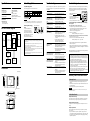
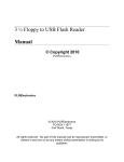
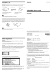
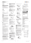
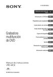
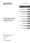
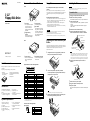
4-668-278-02(1) Names and Functions of Parts Front Installing the Drive Do not attempt to dismantle, repair, or alter the drive yourself Before installing the drive, turn off your computer and unplug it from the AC power outlet. Failure to do so may result in electric shock. Do not, under any circumstances, attempt to dismantle, repair, or alter the drive yourself. You may not only permanently damage the drive and/or your computer, but may also cause fire or personal injury through electrical shock. 3 1/2˝ Floppy Disk Drive Operating and storage environments 1 2 3 4 1 Front Panel User’s Guide Usage Notes 3 Floppy Disk Slot You can replace the front panel to match the color of your computer. For details, see “Replacing the Front Panel and Eject Button”. Insert the floppy disk here. 4 Eject Button Press this button to remove the floppy disk. You can replace the eject button to match the color of your computer. For details, see “Replacing the Front Panel and Eject Button”. 2 Floppy Disk Busy Indicator When data on a floppy disk is accessed, the indicator lights. • Do not place the drive close to heat sources or in direct sunlight; place it in dusty, dirty, or humid locations; place it under precipitation such as rain; or leave it in a vehicle with the windows closed. • If the drive interferes with the reception of radio or television signals, move the drive away from the radio or television. • When using the drive, do not wrap it in cloth, sheets or covers as this may be the cause of malfunctions or fire. WARNING You are cautioned that any changes or modifications not expressly approved in this manual could void your authority to operate this equipment. To prevent fire or shock hazard, do not expose the unit to rain or moisture. To avoid electrical shock, do not open the cabinet. Refer servicing to qualified personnel only. CAUTION To Install the Drive 1 2 For details about this procedure, refer to your computer documentation. 3 4 5 Install the drive into an available drive bay. Connect the floppy disk interface cable to the signal interface connector at the rear of the drive, as illustrated. Signal interface connector Replacing the Front Panel and Eject Button 1 1 MPF920-Z 2 1 Power Connector Floppy disk drive interface cable Pin #1 Pin #1 indicator stripe (usually red or blue) Connector B Notes Holding the drive face front, gently pull the right side of the front panel as illustrated, then remove the panel. • Make sure that the pin #1 indicator strip of the floppy disk interface cable (usually red or blue) is aligned with pin #1 of the 34-pin female connector at the rear of the drive. • To assign the drive as your computer’s A: drive, connect connector A to the signal interface connector. To assign the drive as your computer’s B: drive, connect connector B to the signal interface connector. Make the appropriate changes to the CMOS BIOS. 2 Signal Interface Connector Connect to the power connector from your computer’s power supply. List of Accessories Locate the following cables: • Floppy disk interface cable: flat, “ribbon” type cable with 34-pin female connector. • Power cable: two or four separate wires attached to a single 4-pin female connector. Front panels and eject buttons in alternate colors (granite and mat black) are included for use with different computer case colors. If you want, replace the standard mist white front panel and eject button with one of the replacements, as follows. Printed in China Remove the cover from your computer. Connector A Rear 2002 Sony Corporation Unplug your computer from the AC power outlet. Connect to the floppy disk drive interface cable. 6 Connect the power cable to the power connector, as illustrated. Signal Interface Connector Pin Assignments Power connector When you unpack the carton, make sure that it contains all the accessories listed below. If anything is missing or damaged, contact your retailer. • MPF920-Z (Mist white front panel and eject button) • • • • Front Panels (granite and mat black) Eject Buttons (granite and mat black) User’s Guide Warranty Card Introduction The MPF920-Z (hereafter referred to as the “drive”) has the following features: ❏ Compatible with 1.44 MB and 720 KB, 31/2 in. floppy disks. ❏ Easy to install. ❏ Superior design and construction. ❏ Replaceable colored front panel and eject button. System Requirements The drive can be used with a computer with the following specifications: ❏ IBM PC-compatible system ❏ RAM: 4 MB or more ❏ Windows or DOS operating system ❏ 31/2 in., 1.44 MB floppy diskcompatible system BIOS ❏ Floppy disk drive controller or connector ❏ Floppy disk drive interface cable 2 4 32 34 1 3 31 32 2 48.4 mm (1.91 in.) Pin No. 1 3 5 7 9 11 13 15 17 19 21 23 25 27 29 31 33 Pin No. 2 4 6 8 10 12 14 16 18 20 22 24 26 28 30 32 34 Signal Not connected Key*1 Ground Ground Ground Ground Ground Ground Ground Ground Ground Ground Ground Ground Ground Ground Ground Signal Not connected Not connected Not connected INDEX Not connected DRIVE SELECT 1*2 Not connected MOTOR ON DIRECTION STEP WRITE DATA WRITE GATE TRACK 00 WRITE PROTECT READ DATA HEAD 1 SELECT DISK CHANGE *1 Pin #3 of the signal interface connector is physically removed because of the presence of a keying plug on certain connectors (used to prevent incorrect connection). *2 The drive selection is fixed to 1. Power Connector Pin Assignments (EI Connector) 4 3 2 1 2.5 mm (0.01 in.) Pin No. 1 2 3 4 Signal +5 V Ground Ground Not connected To remove the eject button, pull out the eject button. To insert the eject button, align the eject button with the pin and push it until it is fully inserted. Power cable 7 8 9 Reinstall the cover on your computer. Plug your computer to the AC power outlet. Start your computer. The drive is automatically detected. You do not need to install any device drivers. Note Make sure that the eject button is in place before replacing the front panel. 3 Install the new front panel (left side first, as illustrated), and then push the right side until you hear a click. Specifications Floppy disk drive Miscellaneous Compatible disks Power consumption 3.5 in. 2HD (1.44 MB) 3.5 in. 2DD (720 KB) 1.25 W (normal operation) About Floppy Disks Troubleshooting Technical Support Compatible floppy disks Before consulting your Sony representative, verify the following. If you are still unable to identify or solve your problem, consult your retailer or Sony representative. Please consult the above sources before calling with questions about using MPF920-Z, or with technical questions about the drive or the supplied software. If using telephone or e-mail support, please have the following information available: The following floppy disks can be used with the drive. Problem Mass Approx. 430 g (0.95 lb.) Interface These specifications and the appearance of the product are subject to change without notice. 34-pin signal interface Operating and storage environments CAUTION Temperature range • Do not use floppy disks that are incompatible with the drive, as it may damage the drive. • If you use preformatted floppy disks, make sure that they are compatible with your OS. Operating temperature 5°C to 35°C (44°F to 95°F) Protecting data on floppy disks MPF920-Z Block Diagram To prevent accidental loss of important data, use the writeprotect switch on floppy disks. When you slide the switch to the write-protect position, you can read data on floppy disks, but it is impossible to write or delete data. MAIN IC CXA8061Q Signal Interface Connector (34 pins) Floppy Disk Drive Logic Read/Write Head Read/Write Block Back of the floppy disk Write-enable Write-protect position position The computer does not detect the drive. t Your computer and the drive may not be properly connected. Disconnect the drive from the computer and reconnect it. The floppy disk busy indicator does not light when reading or writing data. t The floppy disk drive interface cable, power cable may not be properly connected, or the CMOS configuration incorrect. Verify the connections and CMOS configuration. As soon as the computer is turned on, the floppy disk busy indicator lights and stays lit. t The floppy disk drive interface cable may be connected in the wrong direction. Verify the position of pin #1. If pin #1 is connected properly, replace the cable. The type of the drive is not detected properly upon startup. t The CMOS configuration may be incorrect. Verify the CMOS configuration for drive type: 3.5 in. 1.44 MB. Invalid media or bad Track 00 when formatting. t You attempted to format an HD floppy disk at 720 KB or a DD floppy disk at 1.44 MB. Verify the type of floppy disk in the drive. t The CMOS configuration may be incorrect. Verify the CMOS configuration for drive type: 3.5 in. 1.44 MB. t The drive controller configuration may be incorrect. Refer to the drive controller documentation to verify its configuration. Handling notes Make sure that you take the following precautions when handling floppy disks to ensure the safety of your data. • Do not place floppy disks close to strong magnetic fields such as those generated by speakers or televisions, as this could cause loss of data. • Do not place floppy disks close to heat sources or in direct sunlight as this may warp the floppy disk, making it unusable. • Do not open the floppy disk shutter or touch the disk surface. Dirt or scratches on the disk surface may make reading and writing impossible. • Avoid dropping liquids on floppy disks. • To protect important data, remove floppy disks from the drive and store them in a case when they are not being used. Stepper Driver Spindle Motor IC Cause/Solution The same contents are displayed for different floppy disks. t The drive controller may not be receiving the signal indicating a change of floppy disk. Verify the state of pin #34 and replace the floppy disk drive interface cable, if necessary. t If the cable is in good working order, the drive may be malfunctioning. Contact your local Sony Technical Support Center. Drive not ready error when reading from drive X (where X is the letter of the drive). t There is no floppy disk in the drive. Insert a floppy disk and try again. t Verify the floppy disk drive interface cable. t The drive motor may not be spinning. Contact your local Sony Technical Support Center. Spindle Motor General failure error when reading from drive X (where X is the letter of the drive). Stepper Motor t The floppy disk in the drive is not formatted or not formatted correctly. Use an appropriate floppy disk. t The drive may be out of alignment or otherwise in need of servicing. Contact your local Sony Technical Support Center. Sector not found error. Dimensions (Units: mm (in.)) POWER CONNECTOR Local technical support is available only in the following sales regions: For Customer in the USA (Sony Electronics Inc): • Free telephone support is offered for 90 days from your first call. USA Technical Support only: Web based technical support is free of charge and is available 24 hours a day, 7 days a week. Web site: http://sony.storagesupport.com/ • Toll free: 1-800-588-3847 Monday to Saturday 8:00 a.m.- 8:00 p.m. CT For Products purchased in Australia or New Zealand (Sony Australia Limited): • Web site: http://www.sony.com.au • Toll free: 1300-13-7669 or International 61-2-9887-6666 Monday to Friday 8:30 a.m.- 7:00 p.m. EST • Microsoft, MS, MS-DOS, and Windows are registered trademarks of Microsoft Corporation. • Other system and product names used herein are registered trademarks or trademarks of their respective manufacturers, although the ™ and ® marks are not used in the text. Before using this device, be sure to read the end user license agreements for the software provided with your computer. ❑ Our product guarantee is valid only when the supplied accessories (including software) are used in the specified or recommended system environment, in accordance with this User’s Guide, and applies only to this floppy disk drive. Our customer service and user support apply only under these product guarantee conditions. ❑ Please note that we cannot accept responsibility for failure of the computer or other devices, incompatibility with special hardware, operating problems caused by improper installation of software, loss of data, discs or other accidental or incidental damage that might occur when using this product. ❑ The guarantee and user support for this product are valid only within the countries or sales regions specified on the warranty card. ❑ Copyright laws prohibit the copying of all or part of the User’s Guide, without obtaining permission of the copyright holder. Warranty Card 101.6 (4.0) SIGNAL INTERFACE CONNECTOR t The drive may be out of alignment or otherwise in need of servicing. Contact your local Sony Technical Support Center. Model number: MPF920-Z Serial number Date and place of purchase Computer maker and model number Computer specifications (CPU speed, memory size, OS version, etc.) Warranty Card & After Sales Service • A warranty card should be provided with this product at the place of purchase. • Please read the warranty card, fill in the specified information, and retain it for future reference. • The warranty period is one year from the date of purchase. 144 (5.7) FLOPPY DISK SLOT CAUTION The warranty and technical support service are valid only in the countries or sales regions specified on the warranty card. 3-M3 (0.12) DEPTH 6 (0.24) After Sales Service 60 (2.4) 90 (3.5) 70 (2.8) 21 (0.83) 31 (1.22) Repairs under warranty We provide repair services as described in this guide and on the warranty card. Please contact your supplier or repair service provider for details. Repairs outside the warranty 94 (3.7) P.W.B t The floppy disk in the drive is not formatted or not formatted correctly. Use an appropriate floppy disk. • • • • • If operation can be restored through repairs, we will repair the drive for a charge. Repair requirements 4-M3 (0.12) DEPTH 5 (0.20) If the drive needs repairs, return it to the place of purchase or your repair service provider. • If you return the drive to the place of purchase or your repair service provider because of damage resulting from misuse or other causes, you are responsible for all repair-related expenses, including shipping, handling, and product adjustments.