1
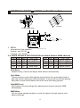
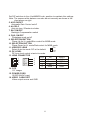
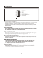
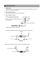
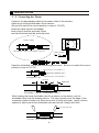
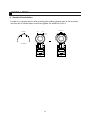
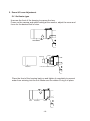
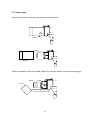
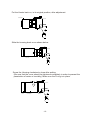
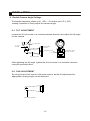
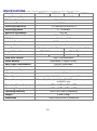
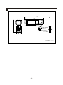
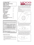
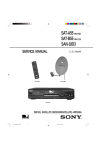
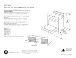
Rugged CCTV
5327 Cedar Creek, Kemp, Texas 75143, USA
Tel: 866-301-CCTV, Fax: 903-498-8989
CAUTION
Risk of Electric Shock
Do Not Open
CAUTION : TO REDUCE THE RISK OF ELECTRIC SHOCK,
DO NOT REMOVE COVER (OR BACK).
NO USER SERVICEABLE PARTS INSIDE.
REFER SERVICING TO QUALIFIED SERVICE PERSONNEL.
This symbol is intended to alert the user to the presence of uninsulated
"dangerous voltage" within the product's enclosure that may be of
sufficient magnitude to constitute a risk of electric shock to persons.
This symbol is intended to alert the user to the presence of important
operating and maintenance (servicing) instructions in the literature
accompanying the appliance.
TABLE OF CONTENTS
PRECAUTIONS
2
FEATURES
2
PART NAMES
3
CONTROLS
4-6
INSTALLATION
7-13
TROUBLESHOOTING
14
SPECIFICATIONS
15
DIMENSIONS
16
-1-
PRECAUTIONS
Safety
The camera should be operated only from the type of power source indicated on
the marking label.
Do not disassemble the camera.
Do not allow anything to get inside of the camera.
Do not drop the camera.
Installation
Camera should be operated within operating temperature range and less
than 90% of humidity.
Avoid installing the camera in harsh environments that include lots of dust,
vibration,or strong magnetic and radio frequencies.
FEATURES
Cable managed bracket with stylish designed bracket assembly, with cables
concealed inside the bracket.
1/3" Format Sony Super HAD CCD
DSP(Digital Signal Processing)to provide a clear, high-resolution image
in all types of lighting situations
Horizontal Resolution of 480 TV Lines
Auto & Manual White Balance
AGC On/Off / BLC On/Off / ELC/ALC Selectable
Dual power (DC 12V or AC 24V)
IP RATE 66 Weatherproof Housing
DC-type auto-iris lens
The optional built-in heater protects the camera from cold environments
(heater operates at 24VAC power only)
-2-
PART NAMES
13
12
11
10
1
2
14
3
4
5
6
7
9
1. GLASS HOLDER : Retaining ring for front glass.
(To keep the unit weather proof, do not unscrew this section)
2. HOUSING : Unscrew this section to gain access to adjust the lens and
dip switches.
3. LENS : Vari-Focal Lens provide manual zoom and focus adjustments to
Set the field of view for the application.
4. LENS MOUNT LOCK : Lock screw used to secure the lens mount.
5. FUNCTION CONTROL BOARD : Board to adjust the various settings of
the camera.
6. AIR VENT : Provides airflow to the internal fan.
(Keep this vent pointed down to prevent water from entering the housing)
7. BRACKET ASSEMBLY : Rear cover and pan/tilt bracket where cables are
concealed and passed through.
8. FAN : If the internal temperature of the camera rises, the fan
will operate automatically to prevent over heating of the camera components.
9. CABLE SET : Cables for power and video
10. BODY : Main section of the camera that contains the electronics.
11. SUNSHIELD LOCK SCREW : Secures the sunshield in the desired position.
12. MOUNT : These holes allow the camera to be top or bottom mounted.
13. SUNSHIELD : Protects the camera from excess heat and glare.
14. OPTIONAL HEATER : Protects the camera from cold environments.
-3-
CONTROLS ( DC12V
/ AC24V~ ) : Dual Power Type
1
10
9
1
DIP SWITCH
11
2
12
4
13
LL 1 ON
3
WB 2 ON
WB 3 ON
5
INT
B
N
W
F
CO
OF
AG
F
F
O F
ELC ON
OF
F
BLC L ON
OF
FLK
A LC
F
F
O
F
6
OF
8
14
7
DIP SWITCH
FUNCTION CONTROL BOARD
16
GND
15
VIDEO
OUT
RED(+)
BLACK(-)
24VAC
OR 12VDC
GREEN(COMMON)
1. INT/LL
MOUNTING PLATE
Internal/Line Lock selection.
Internal : only DC12V
Linelock : only AC24V ~
2~4. WHITE BALANCE SWITCHES(ATW=Auto White Balance /MWB =Manual)
WB1 WB2 WB3
FUNCTION
ON
ON ON
ATW Mode
ON OFF ON
Push Mode
ON OFF OFF Hold/MWB Lock
ON
ON OFF
MWB Mode
WB1 WB2 WB3
OFF ON ON
OFF ON OFF
OFF OFF ON
OFF OFF OFF
FUNCTION
Approx 3200 K
Approx 4200 K
Approx 4700 K
Approx 6300 K
ATW Mode
Default setting. Camera will adjust white balance automatically.
Push Mode
Places camera in auto white balance mode without the usual range limits to
help with certain lighting conditions(Example: a scene with strong red lighting).
May affect overall color balance due to the usual limit being ignored.
Hold/MWB Lock
Will keep the chosen settings after adjusting the camera using the MWB
Mode(below)
MWB Mode
Use the phase up/down buttons to cycle the camera through various color
balance settings.
-4-
Set DIP switches to the <Hold/MWB Lock> position to maintain this settings.
Note :The camera white balance can also be set manually as shown in the
chart above on right.
5. AGC ON/OFF
Automatic Gain Control on/off
6. ALC/ELC
Auto-iris lens / Electronic shutter
7. BLC ON/OFF
Backlight Compensation switch
8. FLKL ON/OFF
Flickerless mode on/off
9. SELECTION BUTTON
Phase Up for LL mode/Blue control for MWB mode
10. SELECTION BUTTON
Phase Down for LL mode/Red control for MWB mode
DC
11. VIDEO/DC LENS
LENS
Select Auto-iris mode. DC is the default.
VIDEO
12. DC LEVEL
LENS
DC Lens level control at auto iris mode.
13. LENS CONNECTOR
VIDEO
PIN
DC
1
1
N.C
Cont. +
1
2
2
VIDEO
Drive
+
2
3
3
B+
Cont. 3
4
4
Drive GND
4
14. CCD
1/3'' imager
15. POWER CORD
12VDC/24VAC input
16. VIDEO CABLE SET
Video output source and GND
-5-
&21752/6
//
,17(51$/6<1&
2))
,17
:% 21
:% 21
2))
:% 21
:% 21
:% 21
2))
:% 21
2))
$*&21
$872*$,1&21752/21
$/&
(/&
(/(&7521,&6+877(5
2))
%/&21
%$&./,*+7&203(16$7,212))
2))
)/./21
)/,&.(5/(662))
326,7,21
,QWHUQDODQG/LQH/RFN6\QF
,QWHUQDO0RGHLVQRUPDOO\XVHGZKHQFRQQHFWLQJWRDPRQLWRU TXDGSURFHVVRU,
PXOWLSOH[HU'95HWF/LQHORFNPRGHLVXVHGWRV\QFKURQL]HDJURXSRI
FDPHUDVWRWKH$&SRZHUVRXUFHWRSUHYHQWWKHSLFWXUHIURPUROOLQJRQEDVLF
VZLWFKHUXQLWV
)/./)OLFNHUOHVV
,I$&SRZHUIUHTXHQF\FKDQJHVWKHIOLFNHURIIOXRUHVFHQWOLJKWFDQEHYLVLEOH
RQWKHPRQLWRU(QDEOHWKLVPRGHWRSUHYHQWWKLV
$*&$XWR*DLQ&RQWURO
7KLVZLOOLQFUHDVHWKHVHQVLWLYLW\RIWKHFDPHUDE\DPSOLI\LQJWKHYLGHRVLJQDO
LQORZOLJKWFRQGLWLRQVWRSURYLGHEHWWHUORZOLJKWSLFWXUHV
%/&%DFN/LJKW&RPSHQVDWLRQ
,QFUHDVHVWKHEULJKWQHVVRIGDUNREMHFWVDJDLQVWDEULJKWEDFNJURXQGWRKHOS
LGHQWLI\LWVIHDWXUHV
0:%0DQXDO:KLWH%DODQFH
7KLVPRGHDOORZVPDQXDOFRQWURORIWKHFRORUV7XUQ:%DQG:%2Q
7XUQ:%2II8VHWKHSKDVHXSGRZQVHOHFWLRQEXWWRQVVHHSDJH
WRDGMXVWWKHFRORU$IWHUDGMXVWLQJWXUQ:%RII
,ULV/HQV&RQWURO
9LGHROHQVLVFRQWUROOHGZLWK95LQOHQVDQG'&OHQVLVFRQWUROOHGZLWK
'&/(9(/95DWWKHIXQFWLRQFRQWUROERDUG
,167$//$7,21
,QLWLDOFKHFN
&KHFNDOOWKHFRQWUROVHWWLQJLQVLGHWKHFDPHUDEHIRUHLQVWDOOLQJLWWRHQVXUHD
VPRRWKWURXEOHIUHHLQVWDOODWLRQ
0RXQWLQJWKHEUDFNHW
&RQQHFWWKHFDPHUDWRWKHPRXQWLQJEUDFNHW
&RQQHFWLQJWKH&DEOH
&RQQHFWLQJWKH9LGHRRXW
3ODFHDSLHFHRIVKULQNDEOHWXELQJRYHU
WKHYLGHRFDEOH
3RZHU&DEOH
9LGHRRXWSXWFDEOH
9LGHRFDEOHWRPRQLWRU'95HWF
6OLGHWKHVKULQNDEOHWXELQJRYHUERWKFRQQHFWRUVDQGDSSO\KHDW
+($7,1*
PP RYHU
PP RYHU
&RQQHFWRU
0ROGLQJ3DUW
$SSO\DVLOLFRQVHDODQWWRERWKHQGVRIWKHVKULQNDEOHWXELQJ
6,/,&216($/$17
INSTALLATION
3 - 2. Connecting the Power
Connect the appropriate cable to the power cable of the camera.
Referring to the specified label of the camera.
(Be sure to match the correct polarity in case of 12V DC)
Insert the cable into the shrinkable
tube A which shall be around 10mm
and tube B which shall be around 3mm.
Power Cable
Shrinkable Tube A Shrinkable Tube B
Power Cable
Heat the shrinkable tube B after connecting each wire. Be sure to match the correct
polarity in case of 12V DC.
RED(12VDC+) OR 24VAC(~)
GREEN(COMMON GND)
BLACK(12VDC-)OR 24VAC(~)
SHRINKABLE TUBE
HEATING
5mm over
Shrinkable Tube A
Shrinkable Tube B
After heating the three shrinkable tube B, as shown on the above, put the
shrinkable tube A as the drawing above. The tube should cover the edge of the
connection parts at least over 5mm and shrink it finally with heat. Apply a silicon
sealant to each ends of the shrinkable tube and shrink it finally with heat.
SILICON SEALANT
Shrinkable Tube A Shrinkable Tube B
-8-
INSTALLATION
4. Sunshield Installation
Locate it in a proper place, after inserting the sliding groove part of the sunvisor
into the rail of holder stand, and then tighten the fixed bolt to fix it.
FIXED BOLT
GROOVE
RAIL
RAIL
HOLDER
STAND
SUNSHIELD
-9-
=RRP)RFXV$GMXVWPHQW
1R+HDWHUW\SH
UnscrewWKHIURQWRIWKHKRXVLQJWRH[SRVHWKHOHQV
Power on WKHFDPHUDDQGZKLOHORRNLQJDWWKHPRQLWRUDGMXVWWKH]RRPDQG
focus for the GHVLUHGILHOGRIYLHZ
+286,1*
=220
)2&86
+286,1*
)81&7,21&21752/%2$5'
3ODFHWKHIURQWRIWKHKRXVLQJEDFNRQDQGWLJKWHQLWFRPSOHWHO\WRSUHYHQW
ZDWHUIURPHQWHULQJLQWRWKHXQLW0DNHVXUHWKHUXEEHU2ULQJLVLQSODFH
&$3
+286,1*
%2'<
+HDWHUW\SH
8QVFUHZWKHIURQWKRXVLQJE\WXUQLQJFRXQWHUFORFNZLVH
+286,1*
+($7(5
+286,1*
6OLGHWKHKHDWHURIIWKHOHQVDUHDDGMXVWWKHOHQVDVVKRZQRQWKHSUHYLRXVSDJH
)2&86
=220
+($7(5
)81&7,21&21752/%2$5'
Put the Heater back on, in its original position, after adjustment.
HEATER
Slide the housing back on as shown below.
HOUSING
Screw the Housing clockwise to close after setting.
(Be sure that the cover should be tightened completely in order to prevent the
penetration of water or humidity.) Make sure the O-ring is in place.
CAP
HOUSING
BODY
-12-
INSTALLATION
6. Flexible Camera Angle Settings
The bracket assembly allows to tilt +25 ~ - 45 and to pan L/R +
- 100 ,
making it possible to freely adjust the camera angle.
6-1. TILT ADJUSTMENT
Loosen the tilt lock screw in a counterclockwise direction and adjust the tilt angle
for the camera.
TILT BRACKET
TILT LOCK
SCREW
MOUNTING
PLATE
CONDUIT HOLE
1-14 UNC
CONDUIT HOLE
3/4-14 UNC
MOUNTING ARM
After adjusting the tilt angle, tighten the tilt lock screw in a clockwise direction
using the provided driver.
6-2. PAN ADJUSTMENT
By using the pan lock screw in the same manner as the tilt adjustment the
appropriate viewing angle can be achieved.
PAN LOCK SCREW
-13-
TROUBLESHOOTING
If there is no picture on the monitor screen,
make sure all the cables are properly connected.
make sure the monitor is properly adjusted.
If the picture on the monitor screen is not clear,
clean the lens.
adjust the lens focus.
If there is a video noise or other unknown problems,
stop using the camera and call your local dealer.
DO NOT DISASSEMBLE THE CAMERA.
IF ANY DEFECTIVE CAMERA HAS BEEN OPENED BEFORE IT
ARRIVES TO AUTHORIZED RMA OFFICE, THE DEFECTIVE CAMERA
MAY NOT BE REPAIRED UNDER ITS WARRANTY SERVICE.
-14-
SPECIFICATIONS ( Note: Design & specifications are subject to change without prior notice.)
Model No.
Image Pick-up Device
RB358
RB358H
RB550
RB550H
SONY 1/3“ Super HAD CCD sensor
Effective Picture Elements
NTSC: 768(H)x494(V)
Horizontal Resolution
480 TV lines
Scanning Frequency
15.734KHz(H)x59.94Hz(V)
Scanning System
2 : 1 Interface
Minimum Illumination
0.5 LUX
Electronic Shutter Speed
1/60 - 1/100,000 Sec
S/N Ratio
More than 48dB
Auto Iris Control
DC Drive Iris Control
Gamma Characteristic
Lens Furnished
Angle Field of View
Heater
0.45
3.5 – 8mm varifocal F1.4
O
O
70 ~33 Horizontal
No
Yes
Auto Gain Control
ELC/ALC Selectable
Synchronous System
Internal, Negative sync.
Video Output
1 Vp-p / 75 Ohms.
12Vdc/24VAC (auto sensing) +/- 20%
12Vdc: 5W (400mA)/ 24VAC: 17W (700mA) heater operates
at 24VAC only
O
O
O
O
-40 F – 122 F (-40 C – 50 C)
O
O
O
O
-14 F – 122 F (-10 C – 50 C)
Operating Humidity
30% to 90% Non Condensing
Weight
Dimensions
Yes
ON/OFF switchable
Iris Control
Operating Temp. (heater)
Operating Temp. (no heater)
No
AWB/MWB (3 Steps Control)
Back Light Compensation
Power Consumption
54O~5.6 O Horizontal
High / Low switchable
White Balance
Power Requirement
5 – 50mm varifocal F1.6
4.8lbs (2.8kg)
75(W)x190(H)x352(D) w/sunvisor
-15-
DIMENSIONS
352
UNITS:mm
-16-