1
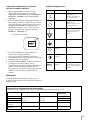
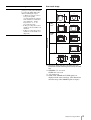
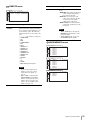
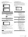
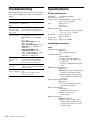
2-546-655-15 (1) LCD Monitor Instructions for Use LMD-2140MD © 2004 Sony Corporation English Owner’s Record The model and serial numbers are located at the rear. Record these numbers in the spaces provided below. Refer to these numbers whenever you call upon your Sony dealer regarding this product. Model No. ____________________ Serial No. ____________________ WARNING To prevent fire or shock hazard, do not expose the unit to rain or moisture. Dangerously high voltages are present inside the unit. Do not open the cabinet. Refer servicing to qualified personnel only. For the customers in Canada This unit has been certified according to Standard CSA C22.2 NO.601.1. In the event of a malfunction or when maintenance is necessary, consult an authorized Sony dealer. FOR THE CUSTOMERS IN THE USA This equipment has been tested and found to comply with the limits for a Class A digital device, pursuant to Part 15 of the FCC Rules. These limits are designed to provide reasonable protection against harmful interference when the equipment is operated in a commercial environment. This equipment generates, uses, and can radiate radio frequency energy and, if not installed and used in accordance with the instruction manual, may cause harmful interference to radio communications. Operation of this equipment in a residential area is likely to cause harmful interference in which case the user will be required to correct the interference at his own expense. This unit contains substances which can pollute the environment if disposed carelessly. Please contact our nearest representative office or your local environmental office in case of disposal of this unit. WARNING THIS APPARATUS MUST BE EARTHED. FOR CUSTOMERS IN EUROPE This equipment has been found to comply with limits for a Class B device pursuant to EN60601-1-2. However, if this equipment does cause harmful interference to other devices, which can be determined by turning this equipment off and on, the user is encouraged to try to correct the interference by one or more of the following measures: • Increase the separation between the equipment and other devices. • Connect the equipment into an outlet on a circuit different from that to which other devices are connected. • Consult the dealer or an experienced radio/TV technician for help. 2 For the customers in Europe This product with the CE marking complies with both the EMC Directive (89/336/EEC) and the Low Voltage Directive (73/23/EEC) issued by the Commission of the European Community. Compliance with these directives implies conformity to the following European standards: EN60950-1 : Product Safety EN55103-1 : Electromagnetic Interference (Emission) EN55103-2 : Electromagnetic Susceptibility (Immunity) This product is intended for use in the following Electromagnetic Environment(s): E1 (residential), E2 (commercial and light industrial), E3 (urban outdoors), E4 (controlled EMC environment, ex. TV studio) You are cautioned that any changes or modifications not expressly approved in this manual could void your authority to operate this equipment. This product contains mercury. Disposal of this product may be regulated if sold in the United States. For disposal or recycling information, please contact your local authorities or the Electronics Industries Alliance (www.eiae.org http://www.eiae.org). Be sure to connect the AC power cord to a grounded outlet. Symbols on the unit Important safeguards/notices for use in the medical environments 1. All the equipment connected to this unit shall be certified according to Standard IEC60601-1, IEC60950-1, IEC60065 or other IEC/ISO Standards applicable to the equipment. 2. When this unit is used together with other equipment in the patient area*, the equipment shall be either powered by an isolation transformer or connected via an additional protective earth terminal to system ground unless it is certified according to Standard IEC60601-1 and IEC60601-1-1. Location This symbol indicates Bottom Main power switch. Press to turn the monitor on. Bottom Main power switch. Press to turn the monitor off. Bottom The equipotential terminal which brings the various parts of a system to the same potential. Bottom Functional earth terminal Front Brightness control Front Contrast control Front Key inhibit The setting are locked so that they cannot be changed. R1 .5 m * Patient Area Symbol 3. The leakage current could increase when connected to other equipment. 4. The operator should take precautions to avoid touching the rear panel input and output circuitry and the patient at the same time. 5. Model LMD-2140MD is a monitor intended for use in a medical environment to display pictures from cameras or other systems. These models are nonpatient care equipment with respect to the requirement of leakage current. 8 6 - Caution When you dispose of the unit or accessories, you must obey the law in the relative area or country and the regulation in the relative hospital. Warning on power connection Use a proper power cord for your local power supply. The United States Canada Continental Europe Plug type HOSPITAL GRADE HOSPITAL GRADE LP-34A Female end E41395 LL33182 LS-60 Cord type E41395-A LL76662 H05VV-F Rated Voltage & Current 10A/125V 10A/125V 10A/250V Safety approval UL CSA VDE 3 Français AVERTISSEMENT Afin d’éviter tout risque d’incendie ou d’électrocution, ne pas exposer cet appareil à la pluie ou à l’humidité. Des courants de hautes tensions dangereuses sont présents à l’intérieur de cet appareil. Ne pas ouvrir le coffret. Se reporter à un personnel qualifié uniquement. Dans le cas d’une défaillance ou de nécessité d’entretien, consulter un revendeur Sony autorisé. Cet appareil contient des substances susceptibles de causer une pollution de l’environnement si elles sont éliminées de façon non conforme. Consultez votre bureau local de préservation de l’environnement pour savoir comment vous débarrasser de cet appareil. AVERTISSEMENT CET APPAREIL DOIT ETRE RELIE A LA TERRE. POUR LES CLIENTS EN EUROPE Cet équipement est conforme aux limitations d’un appareil de classe B ainsi qu’il est stipulé par la norme EN60601-1-2. Cependant, si cet équipement est la source d’interférences néfastes à d’autres appareils, ce qui peut être déterminé en mettant sous tension puis hors tension cet appareil, l’utilisateur est invité à essayer d’éliminer ces interférences en appliquant une ou plusieurs des mesures suivantes : • Eloignez l’appareil des autres appareils. • Raccordez l’appareil sur la prise d’un autre circuit que celui auquel les autres appareils sont raccordés. • Consultez votre revendeur ou un technicien spécialisé en radio/TV pour obtenir de l’aide.. Raccordez le cordon d’alimentation à une prise murale mise à la terre. 4 Pour les clients européens Ce produit portant la marque CE est conforme à la fois à la Directive sur la compatibilité électromagnétique CEM (89/336/CEE) et à la Directive sur les basses tensions (73/23/CEE) émises par la Commission de la Communauté européenne. La conformité à ces directives implique la conformité aux normes européennes suivantes : EN60950-1 : Sécurité des produits EN55103-1 : Interférences électromagnétiques (émission) EN55103-2 : Sensibilité électromagnétique (immunité) Ce produit est prévu pour être utilisé dans les environnements électromagnétiques suivants: E1 (résidentiel), E2 (commercial et industrie légère), E3 (urbain extérieur) et E4 (environnement CEM contrôlé, p. ex. studio de télévision) Pour les clients au Canada Cette unité a été certifiée conformément à la norme CSA C22.2 NO.601.1. Précautions/instructions importantes pour une utilisation dans des environnements médicaux 1. Tous les équipements raccordés à cet appareil doivent être agréés conformément aux normes IEC60601-1, IEC60950-1, IEC60065 ou aux autres normes IEC/ISO applicables à ces équipements. 2. Si cet appareil est utilisé conjointement avec d’autres appareils à proximité du patient*, l’équipement doit être alimenté par un transformateur d’isolement ou raccordé via une borne de mise à la terre supplémentaire pour relier le système à la masse à moins qu’il ne soit certifié conforme aux normes IEC60601-1 et IEC60601-1-1. Symbole Emplacement Signification du symbole En bas Interrupteur d’alimentation. Appuyez sur cette touche pour mettre le moniteur sous tension. En bas Interrupteur d’alimentation. Appuyez sur cette touche pour mettre le moniteur hors tension. En bas Borne équipotentielle qui ramène les différentes parties d’un système à la même tension. En bas Borne de mise à la terre fonctionnelle Panneau avant Commande de luminosité Panneau avant Commande de contraste Panneau avant Invalidation de touche Les réglages sont verrouillés et ne peuvent être modifiés. R1 .5 m * Proximité du patient Symboles sur l’appare 3. Le courant de fuite peut augmenter si raccordé à d’autres équipements. 4. L’opérateur doit prendre toutes les précautions requises pour ne pas toucher en même temps le patient et les circuits d’entrée et de sortie du panneau arrière. 5. Le modèle LMD-2140MD est un moniteur destiné à être utilisé en milieu médical pour la visualisation d’images transmises par des caméras ou d’autres systèmes. Ces modèles ne sont pas des destinés au traitement des patients en ce qui concerne les exigences liées au courant de fuite. 8 6 - Avertissement Lors de l’élimination de l’appareil et de ses accessoires, vous devez vous conformer aux dispositions légales en vigueur dans votre région ou pays ainsi qu’au règlement de l’hôpital. Avertissement concernant le raccordement au secteur Utilisez un cordon d’alimentation adapté à la tension secteur. The United States Canada Europe continentale Type de fiche TYPE HÔPITAL TYPE HÔPITAL LP-34A Extrémité femelle E41395 LL33182 LS-60 Type de cordon E41395-A LL76662 H05VV-F Intensité nominale minimum du cordon 10A/125V 10A/125V 10A/250V Certification de sécurité UL CSA VDE 5 Deutsch WARNUNG Um Feuergefahr und die Gefahr eines elektrischen Schlages zu vermeiden, darf das Gerät weder Regen noch Feuchtigkeit ausgesetzt werden. Im lnneren des Geräts liegt gefährliche Hochspannung an. Öffnen Sie niemals das Gehäuse und überlassen Sie Wartungsarbeiten stets nur einem Fachmann. Sollten am Gerät Probleme auftreten oder eine Wartung erforderlich werden, wenden Sie sich an einen autorisierten Sony-Händler. Dieses Gerät enthält Substanzen, die bei unsachgemäßer Entsorgung die Umwelt belasten. Bitte wenden Sie sich an unsere nächste Niederlassung oder an Ihr Umweltschutzamt, wenn Sie das Gerät entsorgen wollen. WARNUNG DIESES GERÄT MUSS GEERDET WARDEN. FÜR KUNDEN IN EUROPA Dieses Gerät erfüllt die nach EN60601-1-2 für Geräte der Klasse B geltenden Grenzwerte. Sollte dieses Gerät jedoch andere Geräte stören (Sie können dies feststellen, indem Sie das Gerät aus- und wieder einschalten), so ist der Benutzer dazu angehalten, die Störungen durch eine der folgenden Maßnahmen zu beheben: • Vergrößerung des Abstands zwischen diesem Gerät und anderen Geräten. • Anschluss des Geräts an einen anderen Stromkreis als den der anderen Geräte. • Ziehen Sie gegebenenfalls Ihren Händler oder einen erfahrenen Rundfunk- oder Fernsehtechniker zu Rate. Schließen Sie das Netzkabel unbedingt an eine geerdete Netzsteckdose an. 6 Für Kunden in Europa Dieses Produkt besitzt die CE-Kennzeichnung und erfüllt sowohl die EMV-Direktive (89/336/EEC) als auch die Direktive Niederspannung (73/23/EEC) des Rats der europäischen Gemeinschaft. Die Erfüllung dieser Direktiven bedeutet Konformität für die folgenden Europäischen Normen: EN60950-1: Produktsicherheit EN55103-1: Elektromagnetische Interferenz(Emission) EN55103-2: Elektromagnetische Empfindlichkeit (Immunität) Dieses Produkt ist für den Einsatz unter folgenden elektromagnetischen Bedingungen ausgelegt: E1 (Wohnbereich), E2 (kommerzieller und in beschränktem Maße industrieller Bereich), E3 (Stadtbereich im Freien) und E4 (kontrollierter EMV Bereich, z. B. Fernsehstudio) Maschinenlärminformations - Verordnung 3.GPSGV, 06.01.2004: Der höchste Schalldruckpegel beträgt 70 dB(A) oder weniger gemäß EN ISO 7779. Symbole am Gerät Wichtige Sicherheitshinweise für die Verwendung des Geräts in der Medizin 1. Alle Geräte, die an dieses Gerät angeschlossen werden, müssen den Normen IEC60601-1, IEC60950-1, IEC60065 und anderen für die jeweiligen Geräte gültigen IEC/ISO-Normen entsprechen. 2. Wenn dieses Gerät zusammen mit anderen Geräten im Patientenbereich* eingesetzt wird, muss es entweder über einen Isoliertransformator mit Strom versorgt oder über einen zusätzlichen Schutzerdungsanschluss gesichert sein, es sei denn, es entspricht den Normen IEC60601-1 und IEC60601-1-1. Symbol Befindet sich Bedeutung an der Unterseite Hauptnetzschalter. Zum Einschalten des Monitors an der Unterseite Hauptnetzschalter. Zum Ausschalten des Monitors. an der Unterseite Äquipotenzialanschluss, der die Spannung der verschiedenen Systemkomponenten aneinander angleicht. an der Unterseite Funktionaler Massepol an der Vorderseite Helligkeitsregelung an der Vorderseite Kontrastregelung an der Vorderseite Tastensperre Die Einstellungen sind gesperrt und können nicht verändert werden. R1 .5 m * Für Patienten zugänglicher Bereich 8 3. Der Ableitstrom kann bei einer Verbindung mit anderen Geräten zunehmen. 4. Der Anwender muss Maßnahmen treffen, um gleichzeitiges Berühren der Ein- und Ausgangskontakte an der Rückseite des Gerätes und des Patienten zu verhindern. 5. Das Modell LMD-2140MD ist ein Monitor für den medizinischen Bereich und dient dazu, Bilder von Kameras oder anderen Systemen anzuzeigen. Aufgrund der Bestimmungen im Hinblick auf Kriechströme gelten diese Modelle als Geräte, die nicht zur Versorgung von Patienten geeignet sind. 6 - Vorsicht Wenn Sie das Gerät oder die Zubehörteile entsorgen, beachten Sie unbedingt die gesetzlichen Vorschriften in der jeweiligen Region bzw. im jeweiligen Land sowie die Vorschriften im jeweiligen Krankenhaus. Warnhinweis zum Netzanschluss Verwenden Sie ein für die Stromversorgung in Ihrem Land geeignetes Netzkabel. USA Kanada Kontinentaleurope Steckertyp HOSPITAL GRADE HOSPITAL GRADE LP-34A Buchse E41395 LL33182 LS-60 Kabeltyp E41395-A LL76662 H05VV-F Nennspannung & Stromstärke 10A/125V 10A/125V 10A/250V Sicherheitszertifizierung UL CSA VDE 7 Español ADVERTENCIA Para evitar incendios o el riesgo de electrocución, no exponga la unidad a la lluvia ni a la humedad. Dentro de la unidad existen altas tensiones peligrosas. No la abra. En caso de avería, solicite los servicios de personal cualificado. En caso de mal funcionamiento o cuando sea necesario el servicio de mantenimiento, consulte a su proveedor Sony. Esta unidad contiene sustancias que pueden contaminar el medio ambiente si no se desecha adecuadamente. Póngase en contacto con nuestro departamento de representación más próximo o con el departamento local de medio ambiente cuando vaya a desechar esta unidad. ADVERTENCIA ESTA APPARATO DEBE CONECTARSE A TIERRA. PARA LOS USUARIOS EN EUROPA Este equipo cumple con los límites de dispositivo de Clase B según EN60601-1-2. No obstante, si este equipo causa interferencias perjudiciales para otros dispositivos, lo que puede comprobarse apagando y encendiendo este equipo, se recomienda al usuario corregir las interferencias realizando una o varias de las siguientes medidas: • Aumentar la separación entre el equipo y los demás dispositivos. • Conectar el equipo a una toma de un circuito diferente al que estén conectados los demás dispositivos. • Consultar con el proveedor o solicitar los servicios de un técnico especializado en radio y TV. Asegúrese de conectar el cable de alimentación de CA a una toma de tierra. 8 Para los clientes del mercado europeo Este producto cumple con las directivas de compatibilidad electromagnética (89/336/CEE) y baja tensión (73/23/CEE) de la Comisión Europea. El cumplimiento de estas directivas implica la conformidad con los siguientes estándares europeos: EN60950-1: Seguridad del producto EN55103-1: Interferencias electromagnéticas (emisiones) EN55103-2: Susceptibilidad electromagnética (inmunidad). Este producto está diseñado para funcionar en los siguientes entornos electromagnéticos: E1 (doméstico), E2 (comercial y pequeña industria), E3 (espacios al aire libre fuera de poblaciones) y E4 (entorno con compatibilidad electromagnética controlada; por ejemplo, en un estudio de TV). Símbolos de la unidad Protecciones de seguridad/advertencias importantes de uso en entornos médicos 1. Todos los equipos conectados a esta unidad deben cumplir las normas IEC60601-1, IEC60950-1, IEC60065 u otras normas IEC/ISO aplicables a los equipos. 2. Si esta unidad se utiliza junto con otro equipo en la zona de pacientes*, dicho equipo debe alimentarse con un transformador de aislamiento, o conectarse mediante un terminal de tierra de protección adicional a un sistema de toma de tierra, a no ser que cumpla las normas IEC60601-1 y IEC60601-1-1. Ubicación Este símbolo indica Parte inferior Interruptor de alimentación principal. Púlselo para encender el monitor. Parte inferior Interruptor de alimentación principal. Púlselo para apagar el monitor. Parte inferio El terminal equipotencial que iguala el potencial de los distintos componentes de un sistema. Parte inferior Terminal de tierra funcional Panel frontal Control de brillo Panel frontal Mando de contraste Panel frontal Inhibición de teclas Los ajustes están bloqueados, de modo que no se pueden modificar. R1 .5 m * Zona de pacientes Símbolo 3. La corriente de fugas podría aumentar si se conecta a otro equipo. 4. El operador debe tomar las precauciones pertinentes para evitar tocar la entrada del panel posterior y la circuitería de salida y al paciente al mismo tiempo. 5. El modelo LMD-2140MD es un monitor destinado a utilizarse en entornos médicos para visualizar imágenes de cámaras u otros sistemas. Estos modelos no son equipos de atención sanitaria hospitalaria en lo que al requisito de corriente de fuga se refiere. 8 6 - Precaución Al desechar la unidad o sus accesorios, se debe cumplir la ley de la zona o país correspondiente y la normativa del hospital correspondiente. Advertencia sobre la conexión de alimentación Utilice un cable de alimentación adecuado al suministro eléctrico local. Estados Unidos Canadá Europa continental Tipo de enchufe TIPO PARA HOSPITAL TIPO PARA HOSPITAL LP-34A Extremo hembra E41395 LL33182 LS-60 Tipo de cable E41395-A LL76662 H05VV-F Corriente y tensión nominal 10A/125V 10A/125V 10A/250V Aprobación de seguridad UL CSA VDE 9 Italiano AVVERTENZA Per evitare incendi o cortocircuiti, l’apparecchio non deve essere esposto alla pioggia o all’umidità. All’interno del televisore sono presenti tensioni pericolosamente alte. Non aprire l’apparecchio. Per le riparazioni, rivolgersi esclusivamente a personale specializzato. Nel caso di malfunzionamenti o di necessarie riparazioni dell’apparecchio, consultare un rivenditore autorizzato Sony. Questo apparecchio contiene sostanze che possono inquinare l’ambiente se non vengono smaltite con le dovute cautele. Per informazioni sulle normative in caso di smaltimento di questo apparecchio, si prega di contattare il nostro rappresentante locale o il centro di informazioni ambientali di zona. AVVERTENZA QUESTO APPARECCHIO DEVE ESSERE COLLOGATO A MASSA. PER I CLIENTI IN EUROPA Questo apparecchio è stato progettato rispettando le norme per i dispositivi di Classe B in conformità agli standard EN60601-1-2. Tuttavia, se durante l’accensione o lo spegnimento il presente apparecchio dovesse provocare interferenze dannose ad altri dispositivi, l’utente è tenuto a correggere tali interferenze adottando le seguenti precauzioni: • Aumentare la distanza tra l’apparecchio e gli altri dispositivi. • Collegare l’apparecchio ad una presa di rete o ad un circuito diverso da quello utilizzato per collegare gli altri dispositivi. • Consultare il rivenditore o un tecnico radio/TV specializzato per risolvere eventuali problemi. Assicurarsi di collegare il cavo di alimentazione CA ad una presa con messa a terra. 10 Per i clienti in Europa Questo prodotto recante il marchio CE è conforme sia alla direttiva sulla compatibilità elettromagnetica (EMC) (89/336/CEE) che alla direttiva sulle basse tensioni (73/23/CEE) emesse dalla Commissione della Comunità Europea. La conformità a queste direttive implica la conformità alle seguenti normative europee: EN60950-1: Sicurezza dei prodotti EN55103-1: Interferenza elettromagnetica (Emissione) EN55103-2: Sensibilità ai disturbi elettromagnetici (Immunità) Questo prodotto è destinato all’uso nei seguenti ambienti elettromagnetici: E1 (residenziale), E2 (commerciali e industriali leggeri), E3 (esterni urbani) e E4 (ambienti EMC controllati, ad esempio studi televisivi). Simboli sull’apparecchio Informazioni importanti per la sicurezza nell’uso in ambiente sanitario 1. Tutte le apparecchiature collegate a questo apparecchio dovranno essere in possesso di certificazione in conformità alle norme IEC60601-1, IEC60950-1, IEC60065 o altre norme IEC/ISO applicabili. 2. In caso di utilizzo insieme ad altre apparecchiature in aree destinate a pazienti* l’apparecchio dovrà essere dotato di trasformatore oppure dovrà essere collegato mediante un terminale di terra supplementare all’impianto di messa a terra, a meno che già in possesso di certificazione conforme alla norme IEC60601-1 e IEC60601-1-1. Simbolo Posizione Significato Lato inferiore Interruttore principale di alimentazione. Premere questo tasto per accendere il monitor. Lato inferiore Interruttore principale di alimentazione. Premere questo tasto per spegnere il monitor. Lato inferiore Terminale equipotenziale che porta le varie parti di un sistema allo stesso livello. Lato inferiore Terminale funzionale di terra Pannello anteriore Controllo luminosità Pannello anteriore Controllo contrasto Pannello anteriore Inibizione tasto Le impostazioni vengono bloccate per impedirne la modifica. R1 .5 m * Aree destinate a pazienti 8 3. La corrente di dispersione può aumentare se collegato ad altre apparecchiature. 4. L’operatore deve fare attenzione a non toccare contemporaneamente i circuiti di entrata e uscita del pannello posteriore e il paziente. 5. Il modello LMD-2140MD è un monitor concepito per l’impiego nel settore medico. Serve a visualizzare immagini provenienti da videocamere o da altri sistemi video. Questi modelli non sono progettati per le aree di cura dei pazienti per quanto riguarda le norme relative alla dispersione di corrente. 6 - Attenzione In fase di smaltimento dell’unità o degli accessori, rispettare la legislazione locale o le normative vigenti sul luogo di lavoro. Avvertenza sul collegamento dell’alimentazione Utilizzare un cavo di alimentazione adeguato all’alimentazione del Paese in cui ci si trova. Stati Uniti Canada Europa continentale Tipo di spina PER L’USO IN OSPEDALE PER L’USO IN OSPEDALE LP-34A Terminale femmina E41395 LL33182 LS-60 Tipo di cavo E41395-A LL76662 H05VV-F Tensione e corrente nominale 10A/125V 10A/125V 10A/250V Approvazione di sicurezza UL CSA VDE 11 ᶑ㓫 嫊⎮ 嬢⡫ᵮ䗨䪊⍛ 䪊⍛ ằ仒 䪊⍛⎏ᶭ ⷹ恌 ᶟ䒙㷴⃗Ɂ ㉭ᵤᵯ㫈⃗ㆷ䘵太 ◌Ɂ ⷹ恌 ᶟ䒙㷴⃗Ɂ ㉭ᵤᵯ㫈⃗⃗救䘵太 ◌Ɂ ⷹ恌 ợ䱟乃ㆤ㙭恌Ṛὁ㉥⍰ ᵤ䒙ằ䗨䪭䒙ằ㌉⚔䩓 ⪴Ɂ ⷹ恌 ∃偡㌉⚔䩓⪴ 8 ↱曆 Ḓ⸊㌋↚ 6 ↱曆 ⭝㬸⸊㌋↚ ↱曆 摥⫾撒 「⍓ṉ⭪嬢仒摥⫾濇弽 㞛⍓ṉ斖㫆⭝⃚弿垰ὒ 㒝Ɂ ᶞᷪ斖㫆䒙⅟Ẉ⬗濇孛ᵱ壥⭪㫈嬢⡫㘘暖⚌晌ᶑㅺ 㻒㷣䗨䌓⟧ᶑɁ 㫈嬢⡫⃩恌㙭樼⋯䒙濇孛≣ㆷ㚞⡗Ɂ⣦㜀嬢⡫⅞ 䌔㒩昀孛ᵷᵾḞ⎼岃岇乘ὒɁ ⣦㜀嬢⡫晤壥乘ὒㅺ乘㈈濇孛侸䱟㋬㚧䗨 Sony 丳 摤⒪Ɂ ⣦㜀㫈嬢⡫⡨仒ᵱ⺷濇⫧⎏㙭䗨䇍岌Ṿ⭝䌓⟧径ㅴ 㯅㜷Ɂ⣦㜀晤壥⡨䍪㫈嬢⡫濇孛侸䱟⺷⚔䗨ṇ埌⡨ ㅺ䌓⟧恌敌Ɂ 嫊⎮ 㫈嬢⡫⼩柟凓⣡㌉⚔Ɂ 孛⭪ AC 䒙㷴丣彂㌉↔㙭㌉⚔䗨㌶⸋ᶑɁ - 12 ᶑ㓫 䒆␥ᵮ䗨䪊嗃 䪊嗃 ằ仒 䪊嗃び伍 ⷹ恌♺ ᶟ晟㷴擯敀Ɂ ㉭ᵯ⋗⍓擯Ⓝ妑´晟 㷴Ɂ ⷹ恌♺ ᶟ晟㷴擯敀Ɂ ㉭ᵯ⋗⍓敀擭妑´晟 㷴Ɂ ⷹ恌♺ 䪭晟ằ䲦䩓ợ妑´⍨恌 Ṛ䗨晟ằ䙜䪭Ɂ ⷹ恌♺ ∃偡㌉⚔䲦䩓 8 㫇曆♺ Ḓ⸊㌋↚慹 6 㫇曆♺ ⭱㬸㌋↚慹 㫇曆♺ ㉭拙ㇵ↚ 拺ẳ妑⫾ᾠ濇ṉ忣₱嫮 㙘⫧ήɁ 嫊⎮ 剉壥忣₱峛㿏ㅺ晟㐮⋕明濇娯≣⭫㚐㧃◌㙁暖⚌晌 ᶑㅺ㻒㼹䐔⟧ᶑɁ 㧃◌恌㙭⋕明樼晟⠷Ɂ娯≣擯Ⓝ㧃㬠Ɂ娯 䒕⍬ 㞠䗨䴑ὒḞ⑅徖垰䴑ὒɁ 剉䗠䒃㒩昀ㅺ晤壥䴑ὒ㖦濇娯㲡㋬㩮䗨 Sony 䳷戛 ⒪Ɂ 㚐㧃◌≩⎏⍓偡㯅㜷䐔⟧䗨䇍屎濇⼩杬⭳⼧喹䍪Ɂ 娯俓䳅「㙤張䗨ṇ埌弊⃐⬈ㅺ䓚⚔䗨䐔ὁ㧃敀濇Ừ 㲡姆㠨仒喹䍪㚐㧃◌䗨ᷯ⬀Ɂ 嫊⎮ 㫈妑´⼩杬㌉⚔䴾Ɂ 娯䠞⫾ AC 晟㷴䴾徇㌉兗㙭㌉⚔䗨晟㷴㌶⸋Ɂ - 13 ैĜؗ ëò ߾ۊԂ ڬŅॸ Ņॸ ߾ڌ Ņॸڬ ڬП 㧲គ ⶖ Ⲟ⭪ ✾⮞㋲ . Ⰾ ✾⮞㋲Ḗ ᚦᲆ ὂᝢ 㗊Ḗ ㏇ᝢ . 㧲គ ⶖ Ⲟ⭪ ✾⮞㋲ . Ⰾ ✾⮞㋲Ḗ ᚦᲆ ὂᝢ 㗊Ḗ ᓯᝢ . 㧲គ ❶✾㗶⯲ ⪆ᲆ √∞⯞ ᡳⰖ㧶 Ⲟ⮞ᳶ Ṧᜮ ᦋⲞ⮞ គⰪⰟᝢ . 㧲គ ⲫ⹚ គⰪ 8 ⲞἎ ₷ዊ ⴊⲯ 6 ⲞἎ ㎂㝒ᰖ✾㝒 ⴊⲯ ⲞἎ 㔾 ⴊⰫ ኢ⹚ ▾ⲯⰎ ⅚ᅗᢲ⹚ ⧤ᡞ᳷ ᳷㔆ᣃᝢ . ংیlj ۡ ڌय़ ڠйܹॆ͘Ϟ ¦߾ۊЃŅlj Ņ بȊߡʢܹ ׳ʐͦ ॆ֕֎ ه. ߾ۊǚѿبȿ ò ڱӶٲʢКͥ ڌय़ौɌɖ . ۢ ɨ ѬΛ ܹشΫ֕֎ ه. ڿâ ڻȿ ۡЁ ۧҢ ٫ٿ έ ԚҢօΛ ֒֎ॏ؈ ौɌɖ . ⪾ᡳⰫⰎ ₶╷㧲ᄊᔲ ⮺⹚ ⚲ႚ 㧞⬮㧲Ἆ Sony ᆏ Ⱂ រṆⲪ⩪ ῒ⯲㧲➇❶⪾ . Ⰾ ⰿ㋲⩪ᜮ √ⶖ⯲㧲ᄦ 㡪ዊ㧺 ᅗ⭊ 㫲ᅗ⯞ ⪾⪖❶ 㕆 ⚲ Ⱒᜮ ῖⰎ 㢆㨂ᢲ⩎ Ⱒ❏ᝢ . Ⰾ ⰿ㋲Ḗ 㡪 ዊ㧺 ᅗ⭊⩪ᜮ ႚዦ⭎ ន╆ ▶⋞✾ ◖㗊ᔲ ⹚⪇ 㡪 ዊῖ ㄲṆ ◖㗊⩪ ῒ⯲㧲➇❶⪾ . ëò ߾ۊ ڱȿ ܹۥʢؗ؈έ ौɌɖ . AC Ⲟ⭪ ㏮ᜮ ⲫ⹚ ㏲◖㝒⩪ 㫯❾㰢 ⪊ᅊᢲ⩎ Ⱒ⩎⨖ 㨃ᝢ . - 14 Table of Contents Precaution ............................................................ 16 On Safety .......................................................... 16 On Installation .................................................. 16 About the LCD Display Panel .......................... 16 About the Fluorescent Tube ............................. 16 On Cleaning ...................................................... 16 Disposal of the Unit .......................................... 17 Recommendation to Use more than One Unit . 17 On Repacking ................................................... 17 On Fan Error ..................................................... 17 Features ................................................................ 17 Location and Function of Parts and Controls .. 19 Front Panel ....................................................... 19 Input Signals and Adjustable/Setting Items ..... 21 Bottom .............................................................. 22 Connecting the AC Power Cord ......................... 23 Attaching the Input Adaptor .............................. 24 Selecting the Default Settings ............................. 24 Selecting the Menu Language ............................ 26 Using the Menu .................................................... 27 Loading USER MEMORY ................................. 28 Adjustment Using the Menus ............................. 28 Items ................................................................. 28 Adjusting and Changing the Settings ............... 29 STATUS menu............................................. 29 COLOR TEMP menu................................... 30 USER CONTROL menu.............................. 30 USER CONFIG menu.................................. 32 REMOTE menu ........................................... 33 USER MEMORY menu............................... 33 Saving the user memory............................... 34 INPUT SELECT menu ................................ 35 KEY INHIBIT menu.................................... 35 USER SERVICE menu ................................ 35 Troubleshooting ................................................... 36 Specifications ........................................................ 36 Dimensions/Mass ................................................. 42 15 Precaution On Safety • Operate the unit on 100 – 240 V AC only. • The nameplate indicating operating voltage, etc. is located on the rear. • Should any solid object or liquid fall into the cabinet, unplug the unit and have it checked by qualified personnel before operating it any further. • Unplug the unit from the wall outlet if it is not to be used for several days or more. • To disconnect the AC power cord, pull it out by grasping the plug. Never pull the cord itself. • The socket-outlet shall be installed near the equipment and shall be easily accessible. • If the unit is used in a cold place, a residual image may appear on the screen. This is not a malfunction. When the monitor becomes warm, the screen returns to normal. • If a still picture is displayed for a long time, a residual image may appear. The residual image will eventually disappear. • The screen and the cabinet become warm during operation. This is not a malfunction. About the Fluorescent Tube • A specially designed fluorescent tube is installed as the lighting apparatus for this unit. If the LCD screen becomes dark, unstable or does not turn on, consult your Sony dealer. On Cleaning On Installation • Prevent internal heat build-up allowing adequate air circulation. Do not place the unit on surfaces (rugs, blankets, etc.) or near materials (curtains, draperies) that may block the ventilation holes. • Do not install the unit near heat sources such as radiators or air ducts, or in a place subject to direct sunlight, excessive dust, mechanical vibration or shock. • Do not place the monitor near equipment which generates magnetism, such as a transformer or high voltage power lines. • When you install the unit to a wall, ceiling, mount arm or operating light, consult to qualified personnel. About the LCD Display Panel • Although the LCD display panel is made with highprecision technology, black dots may appear or bright points of light (red, blue, or green) may appear constantly on the LCD screen. And a color shade or bight shade may appear according to a viewing angle. These are structural properties of the LCD panel and are not malfunctions. • The LCD screen is made with high-precision technology and more than 99.99% of the picture element is intact. However, some of the picture element may not appear or some of the picture element may appear constantly. • Do not leave the LCD screen facing the sun as it can damage the LCD screen. Take care when you place the unit by a window. • Do not push or scratch the LCD monitor’s screen. Do not place a heavy object on the LCD monitor’s screen. This may cause the screen to lose uniformity. 16 Precaution Before cleaning Be sure to disconnect the AC power cord from the AC outlet. On cleaning the monitor A material that withstands sterilization is used for the front protection plate of the medical use LCD monitor. The protection plate surface is especially treated to reduce reflection of light. When solvents such as benzene or thinner, or acid, alkaline or abrasive detergent, or chemical cleaning cloth are used for the protection plate surface/monitor surface, the performance of the monitor may be impaired or the finish of the surface may be damaged. Take care with respect to the following: • Clean the protection plate surface/monitor surface with a 50 to 70 v/v% concentration of isopropyl alcohol or a 76.9 to 81.4 v/v% concentration of ethanol using a swab method. Wipe the protection plate surface gently (wipe using less than 1 N force). • Stubborn stains may be removed with a soft cloth such as a cleaning cloth lightly dampened with mild detergent solution using a swab method and then clean using the above chemical solution. Never use solvents such as benzene or thinner, or acid, alkaline or abrasive detergent, or chemical cleaning cloth for cleaning or sterilization, as they will damage the protection plate surface/monitor surface. • Do not use unnecessary force to rub the protection plate surface/monitor surface with a stained cloth. The protection plate surface/monitor surface may be scratched. • Do not keep the protection plate surface/monitor surface in contact with a rubber or vinyl resin product for a long period of time. The finish of the surface may deteriorate or the coating may come off. Disposal of the Unit • Do not dispose of the unit with general waste. Do not include the monitor with household waste. • The fluorescent tube includes mercury. Dispose of the monitor in accordance with the regulations of your local sanitation authority. Recommendation to Use more than One Unit • As problems can occasionally occur for the monitor, when the monitor is used for safety control of personnel, assets or stable picture, or for emergencies, we strongly recommend you use more than one unit or prepare a spare unit. On Repacking • Do not throw away the carton and packing materials. They make an ideal container which to transport the unit. If you have any questions about this unit, contact your authorized Sony dealer. On Fan Error • The fan for cooling the unit is built in. When the “FAN ERROR” message is displayed, turn off the power and contact an authorized Sony dealer. Features Compliance of safety standards in America, Canada and Europe UL60601-1 for America, CSA C22.2 No.601.1 for Canada and EN 60601-1 for Europe have been obtained for this monitor. The monitor is designed for easy maintenance, with the sheet switch, screen protect panel, etc. Picture Sophisticated I/P (Interlace to Progressive) Conversion The LMD-2140MD provides sophisticated I/P conversion with Sony’s original X-Algorithm technology. This technology combines the pixels above, below and in the diagonal direction of the moving picture part, and then inserts a natural pixel. The direct result is much smoother image reproduction for both moving and static picture areas. Full digital image processing circuitry As well as digital signals, all signals including analog signals are converted into digital signals without any deterioration in the pictures via a full digital image processing circuitry. Two color system available The monitor can display NTSC and PAL signals by connecting this unit. The appropriate color system is selected automatically. Auto chroma/phase function The chroma and phase of the decoder are automatically adjusted with the auto chroma phase function. High-quality LCD panel Because the monitor uses high brightness, high resolution and ultra-wide viewing angle technology, the monitor can be used under various lighting conditions and in numerous ways (hanging on the wall, several ways of monitoring the picture, etc.). Because a color filter with wide-color reproduction and LCD materials with high response speed are used, the motion picture of the video signal is displayed clearer. Input Accepts analog RGB input signals Adopting the scan converter allows this monitor to detect VGA, SVGA, XGA and SXGA analog RGB signals input to the HD15 input connector. Features 17 Accepts DVI-D (digital) input signals Adopting the scan converter allows this monitor to detect VGA, SVGA, XGA and SXGA digital computer signals input to the DVI input connector. To view SXGA signals when the DVI input is selected, use the cable within 3 m (118 1/8 inches) in length. Power saving function The monitor enters into power saving mode to reduce the power consumption when no signal is input. Optional slot for the video signal Two optional input adaptors can be attached. The composite, Y/C, component, analog RGB, SDI or DV signal can be input depending on the input connectors of the board to be used. User memory function You can save the 20 picture settings with the name. The user memory data can be saved or loaded between the monitor and the equipment (PC, etc.) connected in serial remote mode. Multi-format NTSC or PAL color system or DTV format, such as 720P, 1080I, etc. can be selected automatically. Two kinds of ground terminals Two kinds of ground terminals are built into the monitor to equal the electric potential. External sync input The unit can be operated on the sync signal supplied from an external sync generator. External remote control function You can directly select the input signal, aspect, etc. by operating the connected equipment. Functions Other APA (Auto Pixel Alignment) function You can display pictures from the HD 15 input connector in the appropriate size by simply pressing the APA key. Optional stand It is more convenient to install the monitor on a desk by using the optional stand (SU-560). Automatic termination (connector with mark only) The input connector is terminated internally at 75 ohms when nothing has been connected to the output connector. If a cable is connected to the output connector, the internal terminal is automatically released and the signals input to the input connector are output to the output connector (loop-through). Select color temperature and gamma mode You can select the color temperature from among four (HIGH, LOW, LOW2, LOW3) settings and gamma mode from among five settings. You can also adjust the color temperature to the appropriate setting in “USER”. Aspect setting You can set the monitor to 4:3 or 16:9 display mode according to the input signal. Scan function You can select the display from among “NORMAL”, “UNDER”, “OVER”, “ZOOM” and “NATIVE (NTSC, PAL, 480/60I and 575/50I only)”. Select language display You can select your language for the display from seven languages - English, German, French, Italian, Spanish, Japanese and Chinese. 18 Features Key inhibit function You can inhibit the key to prevent missing an operation. Location and Function of Parts and Controls Front Panel 2 APA + – + + – – 4 5 ENTER USER MEMORY MENU INPUT POWER REMOTE - + – 1 3 a [/a (Power) switch Press [ to turn on the power and a to turn off the power. When the power is turned on, the POWER indicator lights. b Tally lamp The lamp lights by the connection to control the tally. For details, refer to “Pin assignment” on page 38. 6 7 8 9 0 qa qs qd f MENU key Press to display the on-screen menu. Press again to clear the menu. The USER SERVICE menu (on page 35) appears by keeping the MENU key pressed. For menu operations, refer to “Using the Menu” on page 27. c APA (Auto Pixel Alignment) key Adjust a picture clearest automatically while a signal is input from the HD15 input connector. To adjust the picture further for finer picture due to the input signal, see the “DOT PHASE” on page 32. Press the MENU key to stop the APA operation. The APA function does not work when the menu is displayed. g Arrow keys (M/m/</,) Select the menu or to make various adjustments. d 8 (Brightness) +/– keys +: press for more brightness. –: press for less brightness. The value is reset to the default setting by pressing the + and – keys simultaneously. j INPUT M/m keys Select the input signal. Each time you press the M key, the input signal switches as follows. When the m key is pressed, the input signal switches in reverse order. e 6 (Contrast) +/– keys +: press to make the contrast stronger. –: press to make the contrast weaker. The value is reset to the default setting by pressing the + and – keys simultaneously. h ENTER key Press to decide a selected item in the menu. i USER MEMORY key Press to load the picture settings saved in the USER MEMORY menu (on page 33). COMPOSITE T r Y/C r RGB r COMPONENT r OPTION A-1 t HD15 R DV I R OPTION B-2 R OPTION B-1 R OPTION A-2 Location and Function of Parts and Controls 19 Notes • The signal set to “OFF” in the INPUT SELECT menu is not selected with the INPUT key and skipped. To select the signal, select “ON”. • When an input adaptor is not attached, “OPTION” is skipped automatically. k - (Key inhibit) indicator When the key inhibit function works, the indicator lights. For the key inhibit function, refer to “REMOTE menu” on page 33 and “KEY INHIBIT menu” on page 35. l REMOTE indicator When the serial remote (RS-232C) is operable, the indicator lights. For the remote function, refer to “REMOTE menu” on page 33. m POWER indicator When the power is turned on, the indicator lights in amber and then in green. This indicator lights in amber in power saving mode. 20 Location and Function of Parts and Controls Input Signals and Adjustable/Setting Items Input signal Item Video*1, B& W*1 Component*2 RGB*2 SDI DV*5 DVI HD15 Y/C*1 SD HD SD HD D1*3 HD*4 CONTRAST a a a a a a a a a a a BRIGHT a a a a a a a a a a a CHROMA a a a a × × × × APERTURE a a a a × × × a × × × × a a (NTSC) × × a a a × × × × × × COLOR TEMP a a a a a a a a a a a AUTO CHROMA/ PHASE a × a a × × a a a × × COMP LEVEL × × a (480/ 60I) × × × × × × × × NTSC SETUP a (NTSC) a (480/60I) × × × × × × × × × GAMMA a a a a a a a a a a a SCAN*6 a a a a a a a a a ASPECT a a a a a SIZE H × × × × × × × × × × × a × × × × × × × APA × × × × × × × × × SHIFT a a a a a a a a a a a DOT PHASE × × × × × × × × × × a POWER SAVING a a a a a a a a a a a PIC DELAY MIN a a a × a × a × a × × PHASE a : Adjustable/can be set × : Not adjustable/cannot be set a a *1 The signal can be input without an input adaptor. When a BKM-227W is attached, a number of the input is increased. *2 The signal can be input without an input adaptor. When a BKM-229X is attached, a number of the input is increased. *3 When a BKM-220D or BKM-243HS is attached, the signal can be input. *4 When a BKM-243HS is attached, the signal can be input. *5 When a BKM-255DV is attached, the signal can be input. *6 You may not be able to set this item due to the input signal. For details, see “Scan mode image” on page 31. Location and Function of Parts and Controls 21 Bottom 1 2 3456 + – + – 8 9 a COMPOSITE connector (BNC) Input connector for composite signals. b Y/C connector (4-pin mini-DIN) Input connector for Y/C signals. c G/Y connector (BNC) Input connector for component Y (luminance) and G of RGB signals. d B/PB connector (BNC) Input connector for PB (blue color difference) of component signals and B of RGB signals. e R/PR connector (BNC) Input connector for PR (red color difference) of component signals and R of RGB signals. f EXT SYNC (External sync) connector (BNC) When this unit operates on an external sync signal, connect the reference signal from a sync generator to this connector. Select “EXT” in “SYNC” of the USER CONFIG menu (on page 32) to use the sync signal through this connector. Note When inputting a video signal with the jitters, etc. the picture may be disturbed. We recommend using the TBC (time base corrector). 22 7 Location and Function of Parts and Controls 0 qa qs qd qf g Optional input slots An optional input adaptor can be attached according to your requirements. Press the INPUT key to select the signals. h /I (Equipotential/Function Earth) terminal (equipotential) terminal Connects the equipotential plug. I (function earth) terminal Connects the earth cable. i AC IN socket Connect the supplied AC power cord. j Loop-through output connectors The signals input to the input connectors (1, b, c, d, e and f) are output here. Connect to the equipment according to the input signal. When the cable is connected to this connector, the 75ohm termination of the input automatically released, and the signal from the input connector is output from this connector. k DVI input connector (DVI-D) DVI Rev.1.0 applicable digital RGB signal is input. To view SXGA signals when the DVI input is selected, use the cable within 3 m (118 1/8 inches) in length. l HD15 input connector (HD D-Sub 15 pin) An analog RGB video signal (0.7 Vp-p, positive polarity) and sync signal are input. The Plug & Play function corresponds to DDC2B. m PARALLEL REMOTE terminal (modular connector, 8-pin) Connects a parallel switch and controls the monitor externally. For safety, do not connect the connector for peripheral device wiring that might have excessive voltage to this modular connector. For details on the pin assignment and factory setting function assigned to each pin, see “Pin assignment” on page 38. Connecting the AC Power Cord Connect the supplied AC power cord as illustrated. The two AC plug holders are supplied. Use one of them that will securely hold the AC plug. 1 n SERIAL REMOTE (RS-232C) terminal (D-Sub 9 pin) Connects to the RS-232C control connector on external equipment connected to the monitor. The monitor can be operated according to control commands sent from external equipment connected to it. Plug the AC power cord into the AC IN socket on the rear panel. Then, attach the AC plug holder to the AC power cord. AC IN socket For details on the pin assignment and function assigned to each pin, see “Pin assignment” on page 38. For details, refer to the Interface Manual for Programmers (saved in the supplied CD-ROM, Japanese and English only). AC cord AC plug holder (Supplied) 2 Slide the AC plug holder over the cord until it locks. To remove the AC power cord Pull out the AC plug holder while pressing the lock levers. Connecting the AC Power Cord 23 Attaching the Input Adaptor Selecting the Default Settings Before attaching the input adaptor, disconnect the power cord. Attach the input adaptor to the optional input slot after removing the panel of the slot. When you turn on the unit for the first time after purchasing it, select the area where you intend to use this unit from among the options. The default setting values for each area 1 Remove the panel of the optional input slot. 3 1 5 4 3 2 2 3 Insert the input adaptor into the slot. 1NORTH AMERICA INPUT MONITOR COMP LEVEL NTSC SETUP Low BETA7.5 7.5 OUT 2LATIN AMERICA PAL&PAL-N AREA NTSC&PAL-M AREA ARGENTINA Low SMPTE 0 PARAGUAY Low SMPTE 0 URUGUAY Low SMPTE 0 OTHER AREA Low BETA7.5 7.5 Low SMPTE 0 NTSC AREA Low BETA7.5 7.5 PAL AREA Low SMPTE 0 High SMPTE 0 3AFRICA AUSTRALASIA 3 COLOR TEMP EUROPE MIDDLE-EAST Tighten the screws. 4ASIA EXCEPT JAPAN 5JAPAN INPUT MONITOR OUT + – + – 24 Attaching the Input Adaptor / Selecting the Default Settings + – MENU + – ENTER USER MEMORY INPUT R - 1 4 If ASIA EXCEPT JAPAN is selected: Customers who will use this unit in the shaded areas shown in the map below should select NTSC AREA. Other customers should select PAL AREA. Press the POWER switch to turn on the unit. The power is turned on and the SELECT SETTING screen appears. 1 North America S E L EC T S E T T I NG xN O R T H A M E R I C A • L A T I N AMER I CA • AFR I CA AUSTRA L AS I A EUROP E M I DD L E - E A S T • AS I A EXCEPT J APAN • J APAN 2 Latin America 3 Africa Australia/New Zealand, Europe, Middle East, Russia 4 Asia Except Japan 5 Japan 2 Press the M or m key to select the area where you intend to use the unit and press the ENTER key. If you select either 1, 3 or 5 The confirmation screen is displayed. Confirm the selected area. When the setting is wrong, press the MENU key to return to the previous screen. AS I A EXCEPT xN T S C A R E A SE L ECT NOR T H TH I S J APAN NTSC area A R E A? • PAL AMER I CA AREA PAL area [ E N T E R ] Y ES [ MENU ] NO 3 If you select either 2 or 4 One of the following screens appears. Press the M or m key to narrow the area further and then press the ENTER key. The confirmation screen is displayed. Confirm the selected area. When the setting is wrong, press the MENU key to return to the previous screen. Press the ENTER key. The area setting is executed and the COMPLETED screen is displayed. C OM P L E T ED NOR T H AMER I CA [EN T ER ] E X I T MENU [ M E N U ] U N D O S E T TI N G S 2 If LATIN AMERICA is selected: Press the MENU key to return to previous screen and undo settings. PAL&PAL-N area L A T I N AMER I CA xP A L & P A L - N A R E A ARGEN T I NA P ARAGUA Y URUGUA Y • NTSC&PA L - M AREA OTHER AREA Argentina Paraguay Uruguay NTSC&PAL-M area Other area 4 Press the ENTER key. The COMPLETED screen is disappeared and the default setting is completed. Note When you have selected the wrong area, set the following items using the menu. • COLOR TEMP (on page 30) • COMP LEVEL (on page 35) • NTSC SETUP (on page 35) See “The default setting values for each area” (on page 24) Selecting the Default Settings 25 Selecting the Menu Language You can select one of seven languages (English, German, French, Italian, Spanish, Japanese, Chinese) for displaying the menu and other on-screen displays. “ENGLISH (English)” is selected in the default setting. The current settings are displayed in place of the x marks on the illustrations of the menu screen. 4 Press the M or m key to select “LANGUAGE”, then press the , or ENTER key. The selected item is displayed in yellow. 5 Press the M or m key to select a language, then press the ENTER key. The menu changes to the selected language. USER CONFIG (1/2) Rr · SYNC xxx xL A N G U A G E xxxxxxx · P O W E R S AV I N G xxx · COMPUTER DETECT··· AU T O C H R O M A / P H A S E · AU T O A D J VA L U E · S TA R T · · · xxx To clear the menu + – + – + Press the MENU key. The menu disappears automatically if a key is not pressed for one minute. + – MENU ENTER USER MEMORY INPUT R – - 1 Press the POWER switch to turn on the unit. 2 Press the MENU key. The menu appears. S TAT U S ( 1 / 2 ) R r F O R M AT COLOR TEMP GAMMA COMP LEVEL NTSC SETUP 3 xxxxxxxxx xxxxxxxx xxx x xxxxx x Press the M or m key to select the USER CONFIG 1/2 (User Configuration 1/2) menu, then press the , or ENTER key. The setting items (icons) in the selected menu are displayed in yellow. USER CONFIG (1/2) Rr · SYNC xxx xL A N G U A G E xxxxxxx · P O W E R S AV I N G xxx · COMPUTER DETECT··· AU T O C H R O M A / P H A S E · AU T O A D J VA L U E · S TA R T · · · 26 Selecting the Menu Language xxx 3 Using the Menu The unit is equipped with an on-screen menu for making various adjustments and settings such as picture control, input setting, set setting change, etc. You can also change the menu language displayed in the on-screen menu. To change the menu language, see “Selecting the Menu Language” on page 26. The current settings are displayed in place of the x marks on the illustrations of the menu screen. Select an item. Use the M or m key to select the item, then press the , or ENTER key. The item to be changed is displayed in yellow. Note If the menu consists of multiple pages, press M or m to go to the desired menu page. 4 Make the setting or adjustment on an item. When changing the adjustment level: To increase the number, press the M key. To decrease the number, press the m key. Press the ENTER key to confirm the number. When changing the setting: Press the M or m key to change the setting. Press the ENTER key to confirm the setting. Note + – An item displayed in blue cannot be accessed. You can access the item if it is displayed in white. + – To clear the menu + – + MENU ENTER USER MEMORY INPUT R – - Press the MENU key. The menu disappears automatically if a key is not pressed for one minute. About the memory of the settings 1 Press the MENU key. The menu appears. S TAT U S ( 1 / 2 ) R r F O R M AT COLOR TEMP GAMMA COMP LEVEL NTSC SETUP 2 The settings are automatically stored in the monitor memory. To reset items that have been adjusted xxxxxxxxx xxxxxxxx xxx x xxxxx x Note Use the M or m key to select a menu, then press the , or ENTER key. The menu icon presently selected is shown in yellow and setting items are displayed. USER CONTROL xC H R O M A · PHASE · APERTURE · GAMMA · ASPECT · SCAN · P I C D E L AY M I N Pressing the M and m keys simultaneously while you are adjusting any of the menu items resets the menu item to the previous setting. The operation may be different from the explanation above. Follow the explanation displayed at the lower part of the menu screen. xx xx xxx x xxx xxxxxx xxx Using the Menu 27 Loading USER MEMORY You can load the picture settings saved in the USER MEMORY menu (on page 34). Adjustment Using the Menus Items STATUS (the items indicate the current settings.) (on page 29) + – + + – 1 MENU + – ENTER USER MEMORY INPUT R – - Press the “USER MEMORY” key. The USER MEMORY menu appears. U S E R M E M O RY ( 1 / 3 ) R r xD E FAU LT · · · · · · 2 3 01 02 03 04 05 06 USER01 USER02 USER03 USER04 USER05 USER06 Select the memory number. < or , key: to move the page M or m key: to select the memory number Press the ENTER key. After loading the picture settings from the selected memory, the menu disappears. To stop selecting the memory Press the USER MEMORY key. The USER MEMORY menu disappears. To reset the settings Select “DEFAULT”, then press the ENTER key. 28 Loading USER MEMORY / Adjustment Using the Menus For the video input FORMAT COLOR TEMP GAMMA COMP LEVEL NTSC SETUP Model name and serial number OPTION A and serial number OPTION B and serial number For the DVI/HD15 input FORMAT fH fV COLOR TEMP GAMMA Model name and serial number OPTION A and serial number OPTION B and serial number COLOR TEMP (on page 30) COLOR TEMP USER CONTROL (on page 30) CHROMA PHASE APERTURE GAMMA ASPECT SCAN PIC DELAY MIN USER CONFIG (on page 32) For the video input SYNC LANGUAGE POWER SAVING COMPUTER DETECT AUTO CHROMA/PHASE SHIFT H SHIFT V RESET For the DVI/HD15 input SYNC LANGUAGE POWER SAVING COMPUTER DETECT AUTO CHROMA/PHASE SIZE H SHIFT H SHIFT V DOT PHASE RESET REMOTE (on page 33) PARALLEL REMOTE SERIAL REMOTE Adjusting and Changing the Settings STATUS menu The STATUS menu is used to display the current status of the unit. The following items are displayed: For the video input S TAT U S ( 1 / 2 ) R r F O R M AT COLOR TEMP GAMMA COMP LEVEL NTSC SETUP xxxxxxxxx xxxxxxxx xxx x xxxxx x S TAT U S ( 2 / 2 ) R r LMD-2140MD xxxxxxx OPTION A BKM-220D xxxxxxx OPTION B N O T I N S TA L L E D • • • • • • • • FORMAT COLOR TEMP GAMMA COMP LEVEL NTSC SETUP Model name and serial number OPTION A and serial number OPTION B and serial number USER MEMORY (on page 33) 01∼20 INPUT SELECT (on page 35) ALL RESET STANDARD INPUT OPTION KEY INHIBIT (on page 35) KEY INHIBIT USER SERVICE (on page 35) FORMAT DISP COMP LEVEL NTSC SETUP USER COLOR TEMP Adjustment Using the Menus 29 USER CONTROL menu For the DVI/HD15 input S TAT U S ( 1 / 2 ) R r F O R M AT fH fV COLOR GAMMA TEMP xxx xxxxxxx xxxxxx xxxx xxxx x The USER CONTROL menu is used for adjusting the picture. Items that cannot be adjusted depending on the input signal are displayed in blue. USER CONTROL xC H R O M A · PHASE · APERTURE · GAMMA · ASPECT · SCAN · P I C D E L AY M I N S TAT U S ( 2 / 2 ) R r LMD-2140MD xxxxxxx OPTION A BKM-220D xxxxxxx OPTION B N O T I N S TA L L E D Submenu • • • • • • • • FORMAT fH fV COLOR TEMP GAMMA Model name and serial number OPTION A and serial number OPTION B and serial number COLOR TEMP xC O L O R T E M P Adjusts color intensity. The higher the setting, the greater the intensity. The lower the setting, the lower the intensity. PHASE Adjusts color tones. The higher the setting, the more greenish the picture. The lower the setting, the more purplish the picture. APERTURE Adjusts the picture sharpness. The higher the setting, the sharper the picture. GAMMA Selects the appropriate gamma mode. You can select from among 5 settings. When “3” is selected, the setting is roughly same as the gamma mode of the CRT (2.2). ASPECT Sets the aspect ratio of the picture. When inputting 16:9 (squeezed) signal from equipment such as a DVD player, set to 16:9. • 4:3: When the picture with ratio 4:3 is input. • 16:9: When the picture with ratio 16:9 (squeezed) is input. SCAN Sets the scan size of the picture. Select from among “NORMAL”, “UNDER”, “OVER”, “ZOOM” and “NATIVE (NTSC, PAL, 480/60I and 575/50I only)” (see “Scan mode image” on page 31). 30 xxxx Submenu Setting COLOR TEMP Select the color temperature from among “HIGH” , “LOW”, “LOW2”, “LOW3”and “USER” settings. • HIGH (D93 or equivalent) • LOW (D65 or equivalent) • LOW2 (D56 or equivalent) • LOW3 • USER: You can set to the color temperature adjusted in the USER SERVICE menu (on page 35). When the mode other than “USER” is selected, the color temperature cannot be adjusted in the USER SERVICE menu. Adjustment Using the Menus Setting CHROMA COLOR TEMP menu The COLOR TEMP menu is used for selecting the color temperature setting. xx xx xxx x xxx xxxxxx xxx Note When inputting the 1035/60I signal, the signal format is displayed as 1080/60I on the screen. A slightly squashed picture is displayed at a little lower position, because the picture is displayed in 1035/1080 picture ratio on a 16:9 screen. Adjust the position to the center using the SHIFT V setting (on page 32). Scan mode image Input Selects to set the delay by the picture processing to the minimum level when the NTSC, PAL, 480/ 60I or 575/50I signal is input. • 0: Mode for giving precedence to the picture quality (recommended mode). This is a mode suitable for an animation and a still picture. It takes longer than “1” or “2” for processing the picture. • 1: The processing time is short and this is a mode suitable for an animation. • 2: The processing time is short and this is a mode suitable for a still picture. 4 16 9 3 NORMAL/ OVER SCAN*2 4 16 3 UNDER SCAN*3 9 16 4 3 9 ZOOM 16 – 9 1024 711 400 768 1024 768 NATIVE*4 533 PIC DELAY MIN Setting Image displayed*1 Submenu 711 *1 The image illustrated shows the input signal by broken line and the efficient picture size by the solid line. *2 NORMAL: 7% over scan OVER: 20% over scan *3 –3% under scan *4 NTSC, PAL, 480/60I and 575/50I signals are displayed in the same size image. (The illustrations show the image when 480/60I signals are input.) Adjustment Using the Menus 31 USER CONFIG menu Submenu You can select a language, etc. The item that cannot be accessed according to the input signal is displayed in blue. POWER SAVING For the video input USER CONFIG (1/2) Rr · SYNC xxx xL A N G U A G E xxxxxxx · P O W E R S AV I N G xxx · COMPUTER DETECT··· AU T O C H R O M A / P H A S E · AU T O A D J VA L U E · S TA R T · · · USER CONFIG xS H I F T H · SHIFT V xxx (2/2) Rr x x AUTO CHROMA/ PHASE Adjusts color intensity (CHROMA) and tones (PHASE). • AUTO ADJ VALUE: Selects “ON” or “OFF” of the Auto adjustment. When set to “OFF”, this parameter is reset to the factory setting. When set to “ON” the automatically adjusted value is enabled. • START...: Display the color bar signals (Full/SMPTE/EIA) on the screen and press the ENTER key. The auto adjustment function starts. After the adjustment is done correctly, the AUTO ADJ VALUE is automatically set to ON. The auto adjustment is stopped by pressing the MENU key during the auto adjustment operation. SIZE H Adjusts the horizontal size of the picture. The higher the setting, the larger the horizontal size of the picture. The lower the setting, the smaller the horizontal size of the picture. SHIFT H Adjusts the position of the picture. As the setting increases, the picture moves to the right, and as the setting decreases, the picture moves to the left. SHIFT V As the setting increases, the picture moves up, and as the setting decreases, the picture moves down. DOT PHASE Adjusts the dot phase. Adjust the picture further for a finer picture after the picture is adjusted by pressing the APA key. RESET Resets the value of SIZE H, SHIFT H, SHIFT V and DOT PHASE to the factory preset value. For the DVI/HD15 input USER CONFIG (1/2) Rr · SYNC xxx xL A N G U A G E xxxxxxx · P O W E R S AV I N G xxx · COMPUTER DETECT··· USER CONFIG (2/2) Rr xS I Z E H · SHIFT H · SHIFT V · D OT P H A S E xxx xxx x x xx · RESET Submenu SYNC LANGUAGE 32 Setting Select the sync signal. • EXT: Select to operate the unit on an external sync signal. When the RGB signal is input, “EXT” is the default setting. • INT: Select to operate the unit on the sync signal included in the monitored signal. You can select the menu or message language from among seven languages. • ENGLISH: English • DEUTSCH: German • FRANÇAIS: French • ITALIANO: Italian • ESPAÑOL: Spanish • : Japanese • : Chinese Adjustment Using the Menus Sets the power saving mode “ON” or “OFF”. When set to “ON”, the monitor goes into power saving mode if no signal is input for about one minute. COMPUTER DETECT... The appropriate preset memory is set for the signal from DVI and HD15 input connector. Select “PRESET1” for the standard PC signal. Select “PRESET2”, “PRESET3” or “PRESET4”when the PC signal is not standard (on page 41). The preset memory is set for each input connector of DVI and HD15. · RESET AU T O C H R O M A / P H A S E · AU T O A D J VA L U E · S TA R T · · · Setting REMOTE menu R E M OT E xPA R A L L E L · SERIAL R E M OT E . . . R E M O T E xxxxxxx Submenu Setting PARALLEL REMOTE Select the REMOTE connector pins for which you want to change the function. You can assign various functions to 1 to 4 pins and 6 to 8 pins. The following lists the functions you can assign to the pins. • – – (“– –”: No function is assigned.) • COMPOSITE • Y/C • RGB • COMPONENT • DVI • HD15 • OPTION A-1 • OPTION A-2 • OPTION B-1 • OPTION B-2 • UNDERSCAN • OVERSCAN • ZOOM • NATIVE • 4:3 • 16:9 • TALLY • EXT SYNC (External Sync) Notes • If you use the parallel remote function, you need to connect cables. For more details, see page 38. • When “OFF” is selected in the INPUT SELECT menu and the function is assigned, the remote function does not work. Select “ON” to use the parallel remote function (on page 35). Submenu Setting SERIAL REMOTE Select one out of following three modes. • RMT OFF: You cannot use the serial remote. Adjust settings by the keys on the front panel. • RMT ON: You can use the serial remote. You cannot use the keys except for the serial remote setting on the front panel. • RMT & LCL: You can use both the serial remote and the keys on the front panel. Notes • When “RMT ON” is selected, the REMOTE and - indicator on the front panel light. • When “RMT & LCL” is selected, the REMOTE indicator lights. USER MEMORY menu U S E R M E M O RY ( 1 / 3 ) R r x0 1 U S E R 0 1 · 02 USER02 · 03 USER03 · 04 USER04 · 05 USER05 · 06 USER06 · 07 USER07 · 08 USER08 U S E R M E M O RY ( 2 / 3 ) R r x0 9 U S E R 0 9 · 10 USER10 · 11 USER11 · 12 USER12 · 13 USER13 · 14 USER14 · 15 USER15 · 16 USER16 U S E R M E M O RY ( 3 / 3 ) R r x1 7 U S E R 1 7 · 18 USER18 · 19 USER19 · 20 USER20 Adjustment Using the Menus 33 Submenu 01∼20 Setting To change the name You can save the setting of the following functions. 1 COLOR TEMP menu • COLOR TEMP USER CONTROL menu • CHROMA • PHASE • APERTURE • GAMMA • ASPECT • SCAN • PIC DELAY MIN USER SERVICE menu • ADJUST GAIN • ADJUST BIAS Front keys • 8 (Brightness) • 6 (Contrast) Press the M or m key to select the memory number in the USER MEMORY menu, then press the , or ENTER key. The USER MEMORY setting menu appears. U S E R M E M O RY ( 1 / 3 ) 01 USER01 xS AV E · · · ·NAME··· 2 Saving the user memory Press the m key to select “NAME”, then press the , or ENTER key. The menu for setting the user name appears. U S E R M E M O RY ( 1 / 3 ) 01 USER01 You can save the 20 picture settings with the name. To load the picture in the saved setting, see “Loading USER MEMORY” on page 28. TtCURSOR R r CHANGE CHAR. R + r DELETE [ E N T E R ] S AV E [MENU]CANCEL To save the picture setting 1 Press the M or m key to select the memory number in the USER MEMORY menu, then press the , or ENTER key. The USER MEMORY setting menu appears. 3 Change the user name. • Press the < or , key to move the cursor to the character position to be changed. • Press the M or m key to change the character. Usable characters: “A to Z”, “0 to 9”, “.”, “/”, “,”, “_”, “-”, “(space)” • Press the M and m keys simultaneously to clear the character. The maximum 18 characters are input for the user name. 4 Press the ENTER key. The settings are saved and the USER MEMORY setting menu appears. U S E R M E M O RY ( 1 / 3 ) 01 USER01 xS AV E · · · ·NAME··· 2 Select “SAVE”, then press the , or ENTER key. The menu for confirming the memory appears. S AV E T O U S E R M E M O RY 0 1 ? [ENTER] YES [MENU] NO 3 Press the ENTER key. The current picture settings are saved and the USER MEMORY setting menu appears. To close the menu without saving the setting Press the < or MENU key. The USER MEMORY setting menu appears. 34 Adjustment Using the Menus To close the menu without saving the setting Press the MENU key. The USER MEMORY setting menu appears. INPUT SELECT menu USER SERVICE menu The input signal set to “OFF” is skipped when the INPUT M/m key is pressed. INPUT SELECT (1/2) Rr xA L L R E S E T S TA N D A R D I N P U T · COMPOSITE · Y/C · RGB · COMPONENT · DV I · HD15 xx xx xx xx xx xx INPUT SELECT (2/2) Rr OPTION xO P T I O N A - 1 · OPTION A-2 · OPTION B-1 · OPTION B-2 xx xx xx xx Submenu Setting ALL RESET All settings are reset to the factory preset ones. STANDARD INPUT Sets the input setting of “COMPOSITE”, “Y/C”, “RGB”, “COMPONENT”, “DVI, and “HD15” • ON: Input signal is selectable. • OFF: Input signal is not selectable. The USER SERVICE menu is provided for any adjustments or settings other than those listed above. To access the USER SERVICE menu, press and hold the MENU key when the menu is not displayed. The item that cannot be accessed according to the input signal is displayed in blue. U S E R S E RV I C E xF O R M AT D I S P ·COMP LEVEL ·NTSC SETUP USER COLOR TEMP ·ADJUST GAIN··· ·ADJUST BIAS··· · COPY FROM OPTION Sets the input setting of an input adaptor. • ON: Input signal is selectable. • OFF: Input signal is not selectable. Setting FORMAT DISP Select the display mode of the input signal and its format. • ON: Input signal and its format are always displayed. • OFF: Input signal and its format are not displayed. • AUTO: Input signal and its format are displayed for about 10 seconds, when the INPUT key is pressed, or the input of the signal begins. COMP LEVEL Select the component level from among three modes. • SMPTE for 100/0/100/0 signal • BETA 0 for 100/0/75/0 signal • BETA 7.5 for 100/7.5/75/7.5 signal NTSC SETUP Select the NTSC setup level from two modes. The 7.5 setup level is used mainly in North America. The 0 setup level is used mainly in Japan. USER COLOR TEMP Adjust the color temperature of “USER” which is selectable in the COLOR TEMP menu. When the color temperature other than “USER” is selected, this cannot be selected. You need to use the measurement instrument to adjust the white balance. Recommended: Konicaminolta color analyzer CA-210 • ADJUST GAIN...: Adjusts the color balance (GAIN). • ADJUST BIAS...: Adjusts the color balance (BIAS). • COPY FROM: If you select “HIGH”, “LOW”, “LOW2” or “LOW3”, the data for the selected color temperature will be copied in the user setting. KEY INHIBIT menu KEY INHIBIT xK E Y I N H I B I T xxx You can lock the setting so that they cannot be changed by an unauthorized user. Select “OFF” or “ON”. If you set to “ON”, all items are displayed in blue, indicating the items are locked. The keys only for setting the key inhibit to “OFF” work. When the key inhibit is set to “ON”, the - indicator on the front panel lights. Note x Submenu Note You cannot set all input settings to “OFF”. xx xxxxx xx When “RMT ON” is selected in the REMOTE menu (on page 33), the - indicator lights and the keys on the front panel do not work. However, “KEY INHIBIT” keeps set to “OFF”. When you want to operate the keys on the front panel, select “RMT OFF” or “RMT & LCL” in the REMOTE menu. Adjustment Using the Menus 35 Troubleshooting Specifications This section may help you isolate the cause of a problem and as a result, eliminate the need to contact technical support. Picture performance Symptom Settlement The display is colored in green or purple. Select the correct input by pressing the INPUT key. The black bars appear at the upper and lower positions of the picture. When the signal aspect is different from that of the LCD panel, the black bars appear. This is not a failure of the unit. The key on the front panel do not work. The key protection function works. The key inhibit function can be set in the KEY INHIBIT menu and REMOTE menu. Set as follows. When “KEY INHIBIT” is set to “ON”: Set to “OFF”. When “SERIAL REMOTE” is set to “RMT ON”: Set to “RMT OFF” or “RMT & LCL”. When “KEY INHIBIT” and “SERIAL REMOTE” are set to “ON”: Set “KEY INHIBIT” to “OFF” and then “SERIAL REMOTE” to “RMT OFF” or “RMT & LCL”. The image is not displayed on the monitor. After confirming the connections and the settings in the INPUT SELECT menu (on page 35), select the correct input by pressing the INPUT key. The image is disturbed. Select “EXT” or “INT” correctly in the “SYNC” setting of the USER CONFIG menu (on page 32). The “FAN ERROR” The fan for cooling the unit does not message is displayed. work. Turn off the power and contact an authorized Sony dealer. 36 Troubleshooting / Specifications LCD panel a-Si TFT Active Matrix Pixel efficiency 99.99 % Viewing angle (up/down/left/right, contrast > 10:1) 85°/85°/85°/85° (typical) Scan Under scan –3 % Normal 7 % Over scan 20 % Efficient picture size Approx. 430 × 322 × 537 mm (w/h/dia) (17 × 12 3/4 × 21 1/4 inches) Resolution H: max. 1,024 dots V: max. 768 lines Aspect ratio 4:3 Display color Approx. 16,770,000 Input/output connectors Input Composite input connector BNC type (1) 1 Vp-p ± 3dB sync negative Y/C input connector 4-pin mini DIN (1) Y: 1 Vp-p ± 3dB sync negative C: 0.286 Vp-p ± 3dB (NTSC burst signal level) 0.3 Vp-p ± 3dB (PAL burst signal level) RGB/Component connectors BNC type (3) RGB input: 0.7 Vp-p ± 3dB (Sync On Green, 0.3 Vp-p sync negative) Component input: 0.7 Vp-p ± 3dB (75% chrominance standard color bar signal) External Sync input connector BNC type (1) 0.3 to 4 Vp-p ± bipolarity ternary or negative polarity binary Remote input terminal Parallel remote Modular connector 8-pin (1) RS-232C (serial remote) D-sub 9-pin (1) HD15 input connector HD D-sub 15-pin (1) R/G/B: 0.7 Vp-p, 75 ohms, sync positive (when G channel is sync negative, the internal sync can be used. 0.3 Vp-p) Sync: TTL level, 2.2 kilohms, polarity free (H/V separate and composite sync) Plug & Play function: corresponds to DDC2B DVI input connector DVI-D (1) TMDS (Single link) Output Video output connectors BNC type (4) Loop-through, with 75 ohms automatic terminal function 4-pin mini DIN (1) Loop-through, with 75 ohms automatic terminal function External Sync output connector BNC type (1) Loop-through, with 75 ohms automatic terminal function General Power AC100 to 240 V, 50/60 Hz, 1.2 A ~ 0.6 A Power consumption Maximum: approx. 100 W (when two BKM-255DV are attached) Maximum: approx. 92 W (when no input adaptor is attached) Peak inrush current (1) Power ON, current probe method: 60 A (240 V) (2) Hot switching inrush current, measured in accordance with European standard EN55103-1: 52 A (230 V) Operating conditions Temperature0 °C to 40 °C (32 °F to 104 °F) Recommended temperature 20 °C to 30 °C (68 °F to 86 °F) Humidity 30 % to 85 % (no condensation) Pressure 700 hPa to 1060 hPa Storage and transport conditions Temperature–10 °C to 40 °C (14 °F to 104 °F) Humidity 0 % to 90 % (no condensation) Pressure 700 hPa to 1060 hPa Accessories supplied AC power cord (1) AC plug holder (2) Instructions for Use (1) CD-ROM (1) Warranty Card (1) Using the CD-ROM Manual (1) Quick Reference (1) When You First Use the Monitor (1) Sales Companies Guide (1) Optional accessories SDI 4:2:2 input adaptor BKM-220D HD/D1-SDI input adaptor BKM-243HS DV input adaptor BKM-255DV NTSC/PAL input adaptor BKM-227W Analog Component input adaptor BKM-229X Monitor stand SU-560 Medical Specifications Protection against electric shock: Class I Protection against harmful ingress of water: Ordinary Degree of safety in the presence of flammable anesthetics mixture with oxygen: Not suitable for use in the presence of flammable anesthetics mixture with oxygen Mode of operation: Continuous Design and specifications are subject to change without notice. Specifications 37 Pin assignment PARALLEL REMOTE terminal Modular connector (8-pin) 8 1 Pin No. Signal 1 Designating Y/C input signal 2 Designating RGB input signal 3 Designating OPTION A-1 input signal 4 Designating OPTION A-2 input signal 5 GND 6 Tally lamp ON/OFF 7 Under scan 8 Over scan You can allocate functions using the REMOTE menu (see page 33). Connect the function you want to use with a Remote Control to the Ground (Pin 5). SERIAL REMOTE (RS-232C) terminal D-sub 9 pin, female 5 1 9 Pin No. 38 6 Signal 1 NC 2 RX 3 TX 4 NC 5 GND 6 NC 7 RTS 8 CTS 9 NC Specifications Video signal formats The unit is applicable to the following signal formats. Input 2 Total lines Active lines Frame rate* Scanning format Aspect ratio Signal standard 575/50I (PAL) 625 575 25 2:1 interlace 16:9/4:3 EBU N10 (PAL: ITU-R BT.624) 480/60I (NTSC) 525 483 30 2:1 interlace 16:9/4:3 SMPTE 253M (NTSC: SMPTE 170M) 576/50P 625 576 50 Progressive 16:9/4:3 ITU-R BT.1358 System 480/60P 525 483 60 Progressive 16:9/4:3 SMPTE 293M 1080/50I 1125 1080 25 2:1 interlace 16:9 SMPTE 274M 1125 1035 30 2:1 interlace 16:9 SMPTE 260M/BTA S-001B 1080/60I 1125 1080 30 2:1 interlace 16:9 SMPTE 274M/BTA S-001B 720/60P 750 720 60 Progressive 16:9 SMPTE 296M 1035/60I *1 Output Effective picture size Frame rate*2 Scanning format 575/50I (PAL) 1024 × 576/1024 × 768 50 Progressive 480/60I (NTSC) 1024 × 576/1024 × 768 60 Progressive 576/50P 1024 × 576/1024 × 768 50 Progressive 480/60P 1024 × 576/1024 × 768 60 Progressive System 1080/50I 1024 × 576 50 Progressive 1035/60I *1 1024 × 576 60 Progressive 1080/60I 1024 × 576 60 Progressive 720/60P 1024 × 576 60 Progressive *1 The signal format is displayed as 1080/60I on the screen. A slightly squashed picture is displayed at a little lower position, because the picture is displayed in 1035/1080 picture ratio on a 16:9 screen. Adjust the position to the center using the SHIFT V setting (on page 32). *2 The frame rate is also compatible with 1/1.001. Specifications 39 When an optional input adaptor is installed When BKM-227W/229X is installed Input The unit is applicable to the following signal formats. When BKM-220D/243HS is installed Input Signal standard BKM227W BKM229X 575/50I EBU N10 × a PAL ITU-R BT.624 a × System Signal standard BKM-220D BKM-243HS 575/50I ITU-R BT.656 a a 480/60I SMPTE 253M × a 480/60I SMPTE 259M a a NTSC SMPTE 170M a × 1080/50I SMPTE 292M × a 576/50P ITU-R BT.1358 × a 1035/60I * SMPTE 292M × a 480/60P SMPTE 293M × a 1080/60I SMPTE 292M × a 1080/50I SMPTE 274M × a 720/60P SMPTE 292M × a 1035/60I* SMPTE 260M/BTA S-001B × a 1080/60I SMPTE 274M/BTA S-001B × a 720/60P SMPTE 296M × a When BKM-255DV is installed Input 40 System System Signal standard BKM-255DV 575/50I IEEE 1394-1995 a 480/60I IEEE 1394-1995 a Specifications * A slightly squashed picture is displayed at a little lower position, because the picture is displayed in 1035/1080 picture ratio on a 16:9 screen. Adjust the position to the center using the SHIFT V setting (on page 32). About the preset signal PRESET2 This unit has the preset memory for the signals connected to the DVI and HD15 input terminals (the preset memory). When a preset signal is input, the unit automatically detects the signal type and recalls the data for the signal from the preset memory to adjust it to an optimum picture. This unit is applicable to the following preset signals. PRESET1 DVI fH [kHz] fV [Hz] 1514×483* 31.5 60 1476×576* 31.3 50 1280×483* 31.5 60 1280×576* 31.3 50 Preset signal fH [kHz] fV [Hz] 720×483 31.5 60 720×576 31.3 50 1280×720* 45.0 60 1280×720* 37.5 50 720×483 31.5 60 720×576 31.3 50 1280×720* 45.0 60 1280×720* 37.5 50 Preset signal fH [kHz] fV [Hz] 640×480 31.5 60 PRESET3 Preset signal 640×480 800×600 HD15 1024×768 fH fV [kHz] [Hz] VGA mode 3 31.5 60 VGA VESA 72Hz 37.9 72 VGA VESA 75Hz 37.5 75 VGA VESA 85Hz 43.3 85 VGA Non-CRT 29.5 60 SVGA VESA 60Hz 37.9 60 SVGA VESA 72Hz 48.1 72 SVGA VESA 75Hz 46.9 75 SVGA VESA 85Hz 53.7 85 SVGA Non-CRT 37.0 60 XGA VESA 60Hz 48.4 60 XGA VESA 70Hz 56.5 70 XGA VESA 75Hz 60.0 75 XGA VESA 85Hz 68.7 85 XGA Non-CRT 47.3 60 SXGA VESA 60Hz 64.0 60 SXGA Non-CRT 63.2 60 720×400 VGA TEXT 31.5 70 640×480 VGA VESA 60Hz 31.5 60 1024×768 XGA VESA 60Hz 48.4 60 64.0 60 1280×1024* DVI HD15 Preset signal 1280×1024* SXGA VESA 60Hz HD15 DVI PRESET4 HD15 DVI 1024×768 48.4 60 1280×960* 60.0 60 640×480 31.5 60 1024×768 48.4 60 1280×960* 60.0 60 * Down convert display. VGA, SVGA, XGA, and SXGA are registered trademarks of International Business Machines Corporation, U.S.A. * SXGA is a down convert display. Specifications 41 Side Dimensions/Mass When an optional stand SU-560 is attached Front 302 (12) 44 (1 3/4) 119 (4 3/4) When an optional stand SU-560 is attached 505 (20) 432 (17 1/8) 125 (5) 287 (11 3/8) 236 (9 3/8) 325 (12 7/8) 208 (8 1/4) 28˚* 195 (7 3/4) Unit: mm (inches) *Tilt angle 274 (10 7/8) Mass Approx.9.3 kg (20 lb 8 oz) (When no input adaptor is attached) Approx. 9.8 kg (21 lb 10 oz) (When two BKM-255DV are attached) Top 100 (4) 100 (4) 210 (8 3/8) M4* * Length of M4 screws (4) Monitor cabinet Attached object M4 screw 7 (9/32) to 9 (3/8) 42 Dimensions/Mass Sony Corporation