1
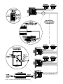
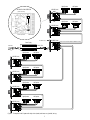
INSTALLATION INSTRUCTIONS
AV C 10 0 R / AV C 10 0 S L / AV C D W P 2
AVC AUDIO DISTRIBUTION SYSTEM
PN.33-1324 7.00
Patent Pending
INTRODUCTION
AVC100SL
Thank you for purchasing an Amplified Volume Control (AVC) product
from Sonance.When properly installed in a system, these products will
provide you with years of entertainment pleasure. To obtain the full
potential of your new purchase, please read all instructions before
starting the installation.If you do not have the necessary skills to install
a unit yourself, please contact your authorized Sonance dealer for
installation options. The AVC100R, AVC100SL and AVCDWP2 are UL
Listed and meet CE requirements EN 60065, EN 55013, EN 50082.
The AVC100SL is a slider-controlled Amplified Volume Control. It is
identical in operation and specifications to the AVC100R, except a
continuously-variable slider is provided in place of a rotary knob.
AVC PRODUCTS
AVC SYSTEM INTERCONNECTION
The AVC system is a new, modular approach to amplifying and
distributing audio for residential and commercial applications.
Depending on installation requirements, your AVC system will be
made up of the following products, as shown in Figure 1:
• Daisy-chain (series) wiring
Recommended Power Supply
Any UL Listed regulated switching power supply, input rated
90-240Vac, output rated 24Vdc, 2.5A with 2.1mm mini-plug and
marked “Class 2”(see specifications on page 4).
The AVC system can be connected in any of the following ways:
• Home-run (parallel) wiring
• Any combination of daisy-chain and home-run wiring
Study the examples in Figures 2 through 3 (on the next two pages) to
learn how to interconnect systems using these wiring schemes.
NOTE: Do not connect a signal power cable to the “SPEAKER” output
connector on any AVC100R/SL. Doing so may damage the unit.
System Expansion
There is virtually no limit on how many AVC100R/SLs are
interconnected in a system, as long as the following conditions
are met:
AVC100R
AVCDWP2
AVC100SL
1. One (1) recommended power supply +24 Vdc powers up to six (6)
AVC100R/SLs. If additional AVC100R/SLs are required in the
installation, connect one (1) recommended power supply for each
additional group of six (6) AVC100R/SLs (see detail in Figure 2 on
page 2).
Figure 1 - AVC system products
2. One (1) AVCDWP2 Driver Wall Plate can drive a system of up to
100 AVC100R/SLs. Beyond that, you will need to divide the system
so it is driven from two or more AVCDWP2s.
WARNING: TO PREVENT THE RISK OF FIRE OR
ELECTRIC SHOCK, DO NOT EXPOSE THIS
APPLIANCE TO RAIN OR MOISTURE.
Adjusting System Levels
CAUTION: RISK OF ELECTRIC SHOCK - DO NOT OPEN
The AVCDWP2 Driver Wall Plate includes two trim pots for individual
adjustment of the system’s left and right audio channels (see detail in
Figure 2 on page 2). At the factory, both trim pots have been set for
+10 dB gain on all three sets of outputs. However, the trim pots
provide an adjustment range from OFF (full CCW) to +19 dB
(full CW).
AVC100R
The AVC100R is a rotary-knob Amplified Volume Control. It provides
the equivalent of 30 watts of amplification at the head end of
conventional audio system run over 100 feet of wire. The knob action
continuously varies the volume of the internal amplifier from zero to
maximum volume. The unit provides 4-conductor quick-disconnect
terminals for input, a looping output, and connection to local
speakers. The AVC100R fits into a standard single-gang plaster ring.
Mono Operation
Each AVC100R or AVC100SL is preset at the factory for stereo
operation. However, this can be easily changed to mono operation by
moving an internal jumper (see detail in Figure 3 on page 3). In this
mode, the blended mono signals are routed to both left and
right outputs.
AVCDWP2
Fuse Replacement
The DWP2 is a Driver Wall Plate for audio distribution of a connected
stereo source and routing of AVC power from a connected
recommended power supply. The unit fits into a standard single-gang
plaster ring. Three parallel four conductor outputs with quick
disconnect terminals are provided. One DWP2 may be used with up
to 100 AVC100R/SLs via standard 16/4 or 14/4 wire. The DWP2 also
provides installer-adjustable gain controls for setting the maximum
system volume level (see the detail in Figure 2 on the next page).
Each AVC100R/SL or AVCDWP2 is protected by an internal fuse (see
detail in Figure 3 on page 3). For safety concerns, only replace a fuse
with the same type and rating.
1
Figure 2 – Example of an AVC system with daisy-chain (series) wiring.
2
AVC100R/SL MONO OPERATION
Right Speaker
Left Speaker
Right Speaker
Left Speaker
AVC100R (side)
Remove (2) Screws
Fuse
AVC100R (side)
Move
Jumper
m
o
n
o
Remove (2) Screws
AVC100R (side)
See detail in Fig. 2
AVCDWP2 (side)
Power Supply
24Vdc, 2.5A
To AC Outlet
DC Power
Right Speaker
Left Speaker
Right Speaker
Left Speaker
Right Speaker
Left Speaker
Right Speaker
Left Speaker
AVC100R (side)
AVC100R (side)
AVC100R (side)
AVC100R (side)
Figure 3 – Example of an AVC system with daisy-chain (series) and home-run (parallel) wiring.
3
NOTE: Do not connect to AVC 100R/SL "SPEAKER" connector.
SPECIFICATIONS
TECHNICAL ASSISTANCE
AVC100R/AVC100SL
If you any have questions about the operation or installation of your Sonance AVC
system products, please call our Technical Assistance Department on any business
day at:
DESCRIPTION:
Local, full-bandwidth, 2-channel distribution amplifier with rotary (AVC100R) or slider (AVC100SL) volume control; fits standard single-gang plaster ring.
POWER OUTPUT:
Continuously-variable from 0 to 7.5 watts (rms) per
channel into a nominal 8-ohm load.
FREQUENCY RESPONSE: 20 Hz ~ 20 kHz
INPUT CONNECTIONS:
(4) Quick-Disconnects; Left, Right, GND, +24 Vdc.
LOOP CONNECTIONS:
(4) Quick-Disconnects; Left, Right, GND, +24 Vdc.
SPEAKER CONNECTIONS: (4) Quick-Disconnects; Left +, Left –, Right +, and
Right –. Load is 4 ohms per channel, minimum.
STEREO/MONO MODES: Selectable via internal jumper.
FUSE:
Internal; type AGC, 1 A, 250 V.
DIMENSIONS:
4-3⁄32" H X 1-5⁄8" W X 4-1/4" D (overall)
2-3⁄4" H X 1-5⁄8" W X 3-3⁄8" D (in-wall)
AVCDWP2
DESCRIPTION:
Stereo driver amplifier connects to hi-fi stereo
source and up to 100 AVC100R/SLs; fits standard
single-gang plaster ring.
(2) color-coded, stereo RCA jacks; 50 kΩ input
INPUT CONNECTIONS:
impedance.
OUTPUT CONNECTIONS: (3) sets of (4) Quick-Disconnects: Left, Right, GND,
and +24 Vdc.
FREQUENCY RESPONSE: 20 Hz ~ 20 kHz
POWER CONNECTIONS: Female, 2.1 mm, mini-plug connects to
recommended power supply.
GAIN CONTROL:
(2) L/R trim pots provide +19 dB adjustment range.
FUSE:
Internal; type AGC, 0.5 A, 250 V.
DIMENSIONS:
4-3⁄32" H X 1-5⁄8" W X 3-5/8" D (overall)
2-3⁄4" H X 1-5⁄8" W X 3-3/8" D (in-wall)
Minimum Recommended Power Supply Specifications
Description:
CURRENT DRAW:
AC CONNECTIONS:
DC CONNECTIONS:
Marked:
+24 Vdc, 2.5 A, voltage-regulated switching power
supply with short-circuit protection; for use with up
to six (6) AVC100R/SLs.
1.5 A maximum at 50 watt rating
110 Vac male IEC plug with supplied power cable
connects to standard 110 Vac outlet. Multi-voltage
input auto-switches from 110~240 Vac (50 ~60 Hz)
for use in Europe or Australia.
6' attached cable with male, 2.1 mm, mini-plug for
connection to AVCDWP2.
UL Listed “Class 2”
(800) 582-0772 or (949) 492-7777; between 9 A.M.and 5 P.M.,PST
OBTAINING SERVICE
If your product should need repair or service,contact your authorized Sonance dealer
for help.
WARRANTY COVERAGE (USA ONLY)
Sonance offers you a one (1) year limited warranty on each of your AVC products.You
must observe the following conditions in order to receive this protection:
1. Retain your bill of sale or legible facsimile (photocopy).If your unit(s) should ever
require service, the bill of sale shall act as your proof of ownership and give the
effective date of your warranty.
2. Read the below warranty thoroughly.Sonance offers you certain rights outlined in
your warranty and requires specific conditions to be met.You may also have other
rights which vary from state to state.
One-Year Limited Warranty
Sonance warrants to the original purchaser for the period of one (1) year,each AVC unit
to be free from defects in material and workmanship provided each unit is operated in
accordance with the printed instructions included with the unit.One (1) year begins on
the date of purchase shown on the bill of sale (receipt).
For this warranty to be effective,the bill of sale must also show from whom each unit
was purchased and the purchase price. In the event proof of purchase cannot be
established as stated in the previous sentence(s),warranty shall commence on the date
each unit was shipped from the factory,provided the serial number on each unit has not
been altered or in any way tampered with.This warranty shall apply exclusively to the
original purchaser and shall not apply to purchasers who purchased units solely for
industrial or commercial purposes.
During the warranty period, Sonance agrees to repair or, at its discretion,
replace at no charge components that prove to be defective, provided a unit is
returned in accordance with the shipping instructions found within the
product installation instructions/owner’s manual. This warranty does not
apply if a unit has been damaged by accident or misuse, or as a result of
service or modification by unauthorized personnel.
This warranty is limited to Sonance product(s) registered herein and specifically
excludes any damage to loudspeakers and other allied or associated equipment which
may result for any reason from use with this product.
The warranty set forth above is in lieu of all other warranties, express or implied, of
merchantability,fitness for a particular purpose or otherwise.Inno event shall Sonance
be liable for incidental or consequential damages or have any liability with respect to
defects other than as specifically set forth above.
Declaration of Conformity
We, Sonance
212 Avenida Fabricante
San Clemente, CA 92672
U.S.A.
declare in own responsibility, that the products described in this owner’s
manual is in compliance with technical standards:
EN 60065 : 1994
EN 55013 : 1990
EN 50082 : 1992
7/00
Sonance
San Clemente, CA
U.S.A.
212 Avenida Fabricante • San Clemente, CA 92672-7531, USA • (800)582-7777 or(949)492-7777 • FAX: (949)361-5151 • Technical Support: (800) 582-0772