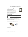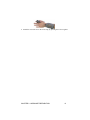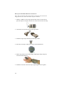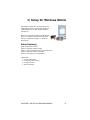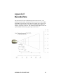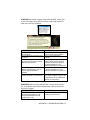
1
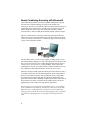
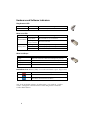
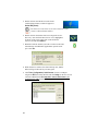
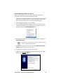
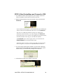
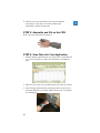
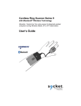
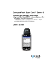
Cordless Ring Scanner Series 9
with Bluetooth® Wireless Technology
Featuring a “Hands-Free” wearable bar code scanner that
captures and sends data wirelessly to Bluetooth enabled
computers running Windows Mobile, XP or XP Tablet Edition.
User’s Guide
9/2006
Document # 6410-00273 G
Copyright Notice
Copyright © 2006 Socket Communications, Inc. All rights reserved.
Socket, the Socket logo and Battery Friendly are registered trademarks of
Socket Communications, Inc. Cordless Ring Scanner with Bluetooth
Wireless Technology, SocketScan, Connect!Agent, Error Proof Protocol
and Mobility Friendly are trademarks of Socket Communications, Inc.
Bluetooth and the Bluetooth logos are trademarks owned by Bluetooth SIG,
Inc., U.S.A. and licensed to Socket Communications, Inc. All other brand
and product names are trademarks of their respective holders.
The Socket Cordless Ring Scanner includes technology licensed under
United States Patent No. 5,902,991.
Reproduction of the contents of this manual without the permission of
Socket Communications is expressly prohibited. Please be aware that the
products described in this manual may change without notice.
Feel free to contact SOCKET COMMUNICATIONS at:
Socket Communications, Inc.
37400 Central Court
Newark, CA 94560
Other than the above, Socket Communications can assume no responsibility
for anything resulting from the application of information contained in this
manual.
Please refrain from any applications of the Socket Cordless Ring Scanner
that are not described in this manual. Please refrain from disassembling the
Cordless Ring Scanner. Disassembly of this device will void the product
warranty.
You can track new product releases, software updates and technical
bulletins by visiting Socket’s web page at: www.socketcom.com.
Table of Contents
COPYRIGHT NOTICE
2
1 | INTRODUCTION
5
About the Software
About Combining Scanning with Bluetooth
System Requirements
Package Contents
Product Registration
Hardware and Software Indicators
Scanning Tips
About the Cable Break Away
5
6
7
7
7
8
9
10
2 | HARDWARE PREPARATION
11
Charging and Installing the Battery
Assembling and Putting on the CRS
11
12
3 | SETUP FOR WINDOWS MOBILE
15
STEP 1: Install the Software
STEP 2: Configure Scanner Settings
STEP 3: Connect CRS to Host Device with Bluetooth
STEP 4: Assemble and Put on the CRS
STEP 5: Scan Data into Your Application
OPTIONAL: Select Symbologies
OPTIONAL: Configure Prefix/Suffixes
OPTIONAL: Configure Sound
OPTIONAL: Run Scan Demo
4 | SETUP FOR WINDOWS XP
STEP 1: Install the Software
STEP 2: Configure Bluetooth Settings
STEP 3: Configure Scanner Settings
STEP 4: Start SocketScan and Connect to CRS
STEP 5: Assemble and Put on the CRS
STEP 6: Scan Data into Your Application
OPTIONAL: Assign Sound and Prefix/Suffix Settings
OPTIONAL: Configure Advanced Bluetooth Settings
OPTIONAL: Assign a Remote Trigger Button
OPTIONAL: Select Symbologies
TABLE OF CONTENTS
16
18
20
22
22
24
25
26
27
28
29
31
37
39
40
40
42
43
45
46
3
APPENDICES
A | SPECIFICATIONS
47
B | SAFETY AND USAGE TIPS
49
C | BAR CODE LABEL SPECIFICATIONS
51
D | ENABLING OR DISABLING SYMBOLOGIES
52
E | DECODE ZONE
55
F | TROUBLESHOOTING
56
G | TECHNICAL SUPPORT
59
LIMITED WARRANTY
60
REGULATORY COMPLIANCE
62
4
1 | Introduction
If you need to collect bar coded data but don't want to be tied to your
mobile or desktop computer, the Socket Cordless Ring Scanner (CRS)
Series 9 with Bluetooth wireless technology is just what you're looking for.
This innovative device combines the power of laser bar code scanning with
the convenience of Bluetooth wireless technology in a compact, lightweight
device that is ergonomically designed to fit comfortably on your hand.
Bluetooth wireless technology transforms how devices connect with each
other, offering new possibilities for using a mobile computer with other
devices. With the CRS, you can scan bar codes while connected to a PDA in
your pocket or a Windows XP system located up to 300 feet away — all
without the hassle of cables or the awkwardness of a protruding antenna.
The CRS was designed with an exclusive Liquidmetal® construction that is
twice as strong as titanium, extremely durable and scratch-resistant. The
Battery Friendly® CRS uses minimal power, so you can scan over 11,000
times in normal operating conditions without having to recharge.
Scanner Versions
The CRS Series 9 includes two versions of the scanner, The Mid-range
CRS 9M has a Class 1 laser scanner and a Class 2 Bluetooth with a
maximum range of 30ft (10m). The Performance CRS 9P features a Class 2
laser scanner with a Class 1 Bluetooth with a maximum range of 300ft
(10m).
About the Software
SocketScan™ enters scanned data directly into any open
Windows program, as if the data were manually typed, so you
can use the CRS with your favorite application. Included is a
utility that enables you to configure Prefix/Suffixes, sounds,
and other special settings for the CRS.
Connect!Agent™ (patent pending) simplifies the Bluetooth by automatically
setting up and managing the Bluetooth connection. Connect!Agent runs in the
background, requiring no user interaction.
For software updates, please visit: www.socketcom.com/support/support_bar.asp
CHAPTER 1: INTRODUCTION
5
About Combining Scanning with Bluetooth
The Cordless Ring Scanner represents an optimal combination of proven
laser bar code scanning technology and state-of-the-art Bluetooth
connectivity. Because of the problems inherent in the intermittent storage of
scanned data in on-board memory if the Bluetooth connection is lost, the
CRS is designed to operate only when connected to the host, with the
powerful Class 1 radio providing the maximum possible connection range.
The user is advised of the connection status with a single beep when the
CRS connects to the host and a double beep when the connection is closed
or lost. As with any wireless device, connectivity range can be affected by a
variety of environmental variables.
The most likely source of errors in any cordless scanning system is not in
the scanning and decoding process, but in the transmission of the data to the
host. To prevent such errors, the Cordless Ring Scanner features Socket’s
exclusive Error Proof Protocol™ (patent pending), which ensures that
scanned data is correctly received by the host computer and allows for realtime validation of data and notification to the user in case of errors.
The beeper and green LED signals provided by the CRS confirm not only a
successful scan but also the successful transmission of the scanned data to
the host. Users familiar with bar code scanning may notice a slight delay
between the successful scan and shut off of the laser, and the beep and
green LED from the CRS confirming completed transmission of the data. In
most instances, this delay is less than 300 ms (milliseconds), but may be
slightly longer as the connectivity range limit is approached.
Because of the two-way transmission verification process, it is possible to
cause communication problems by scanning bar codes as fast as possible.
When this occurs, all transmissions will stop for several seconds before
scanning can be resumed. To prevent this from happening, the user should
wait until the confirming beep is received before scanning the next bar
code.
6
System Requirements
Windows Mobile devices should satisfy these minimum requirements:
• Windows Mobile 2003, 2003SE or 5.0
• Any of the following Bluetooth stacks:
− Broadcom (Widcomm) v1.4
− Microsoft Bluetooth stack for Windows Mobile
− Socket Drakar v1.4 (from Socket SD/CF Connection Kits)
• Software installation requires ActiveSync 4.0 or greater.
Windows XP computers should satisfy these minimum requirements:
• Windows Mobile XP or XP Tablet Edition
• Any of the following Bluetooth stacks:*
− IVT BlueSoleil version 1.6.1.4 (from Socket CF/USB Connection Kits)
− Microsoft Windows XP Service Pack 2 Bluetooth stack
− Toshiba Bluetooth stack 3.03.06
− Broadcom (Widcomm) Bluetooth stack
−
*Other stacks may be compatible but have not been tested by Socket. For Windows XP, only the
IVT and Microsoft Bluetooth stacks are compatible with the optional Socket Connect!Agent
software.
Package Contents
The Socket Cordless Ring Scanner package includes:
• Ring scanner (C)
• Wrist unit (A) with attached cable (B)
• Wrist unit case (D)
• Finger strap (F)
• 2 adhesive Velcro strips (G)
• Rechargeable 3.7V lithium-ion battery
• Battery charger
• CD with software and user documentation
Product Registration
Socket highly recommends that all customers register their Socket products.
Registered users receive the following benefits:
• Priority for technical support
• Special offers for future products and upgrades
• The latest new product information.
Register online at: www.socketcom.com/prodreg
CHAPTER 1: INTRODUCTION
7
Hardware and Software Indicators
Ring Scanner LED
LED
Good Read
LED Activity
Green
Meaning
Data successfully scanned and sent to host device
LED Activity
Blinking blue
every second
Blinking blue,
every 5 seconds
Blinking Red
Meaning
Wrist Unit LEDs
LED
Bluetooth Status
Battery Status
Bluetooth radio is on, no connection
Bluetooth connection
20% battery capacity remaining
Solid Red
10% battery capacity remaining
Off
Off or Good Battery status
Wrist Unit Beeps
Beep Pattern
1 beep
Meaning
Bluetooth connection to host device has begun or power on
2 beeps
Bluetooth connection to host device has ended or power off
1 beep (optional setting)
Data successfully scanned and sent to host device
3 beeps
Cable disconnected from wrist unit
SocketScan Icon Bottom of Today screen when SocketScan is open. Tap for menu.
Icon
Meaning
The CRS is not connected to the host device
The CRS is connected to the host device
Note: In the SocketScan software, the abbreviation “CS” stands for “cordless
scanner” and applies to both the Socket Cordless Ring Scanner and Socket
Cordless Hand Scanner.
8
Scanning Tips
Practice to determine the best scanning angle and distance for your type of
bar code.
Scan Angle
For best results, position the scanner at an angle to the bar code, at least 15°
from perpendicular. Otherwise, light can bounce back into the scanner and
“blind” the sensing mechanism.
Aiming Beam
Aim the laser so that the red beam covers the entire width of the bar code.
CHAPTER 1: INTRODUCTION
9
Scanning Distance
•
•
•
The optimal scanning distance varies depending on the bar code size,
symbology, label media, W-N Ratio, and scan angle. In general, the
CRS can successfully scan 2.2 to 30+ inches from the bar code.
The larger the bar code, the further away you should position the
scanner.
The tighter the bars of the bar code, the closer you should position the
scanner.
About the Cable Break Away
The CRS is designed to break away from the hand if subjected to unusual
force. This break away feature is designed to reduce the possibility or extent
of injury to the body in the event the CRS becomes entangled in industrial
equipment.
If the cable breaks away from the ring scanner unit during use, simply plug it
back in to resume operation.
Note: Whenever the cable disconnects from the ring scanner, it will beep 3
times.
10
2 | Hardware Preparation
Charging and Installing the Battery
1. The battery must be charged before initial use,
using the included Socket charger. The
Charging LED will be yellow during charging.
After approximately 4 hours, the battery will
reach full charge, indicated by a green Charging
LED.
Do not use the charger with other types of batteries. A
fully charged battery should provide at least 10,000
scans and more than 8 hours of operation.
Battery Charger LEDs
LED
Power
Charging
LED Activity
Red
Meaning
Plugged into valid power source
Yellow
Charging
Green
Battery is fully charged
You can also check the battery level by checking the CS HW screen of the
SocketScan settings utility. The utility will report the battery level only when the
CRS is connected to your mobile computer.
2. Slide the switch at the bottom of the wrist unit to unlock the battery door.
Insert the battery so that the battery contacts align with the contacts
inside the wrist unit, then close and lock the battery door.
WARNING: Do not insert the battery backwards or upside-down.
Damage may result.
CHAPTER 2: HARDWARE PREPARATION
11
Assembling and Putting on the CRS
You can put on the CRS either with or without the case. If you choose not to
use the case, the plastic parts of the wrist unit will be more susceptible to
abuse.
How to put on the CRS with the wrist unit case
1. Insert the wrist unit into the case, pulling the free end of the cable
through the hole in the top of the case. During insertion, you may hear a
beep and see the LED flicker because the power button was pressed,
however, the wrist unit will not turn on unless the button was pressed for
more than 2 seconds, and the LED continues to blink.
2. Connect the free end of the cable to the ring scanner.
3. Attach the finger strap to the bottom of the ring scanner. To insert the
clips, grasp it with the thumb and index finger. Insert one end of the clip
post into the slot, gently push down, and then push the other end of the
post in for a snug fit. To remove the finger strap, grasp the clips with the
thumb and index finger then pull one side of the clip out and remove. Do
not twist the clips upon insertion or removal—this may cause the
clips to break.
4. Put on the wrist strap. Adjust it for a secure and comfortable fit.
5. Put the ring scanner on your index finger, adjusting the finger strap for a
secure and comfortable fit.
12
6. Attach the wrist unit case to the wrist strap, by pressing the Velcro together.
CHAPTER 2: HARDWARE PREPARATION
13
How to put on the CRS without the wrist unit case
Note: After you stick the Velcro strips to the wrist unit, the wrist unit will no
longer fit in the case, unless the Velcro strips are removed.
1. Stick the 2 adhesive Velcro strips onto the back of the wrist unit. Do not
space the strips too far apart. Note the size of the Velcro on the wrist strap.
2. Connect the free end of the cable to the ring scanner.
3. Attach the finger strap to the bottom of the ring scanner.
4. Put on the wrist strap. Adjust it for a secure and comfortable fit.
5. Put the ring scanner on your index finger, adjusting the finger strap for a
secure and comfortable fit.
6. Attach the wrist unit to the wrist strap, by pressing the Velcro together.
14
3 | Setup for Windows Mobile
This chapter explains how to install and use the
Cordless Ring Scanner (CRS) with a Bluetooth
enabled Pocket PC or other Windows Mobilebased device.
Before you begin the instructions in this chapter,
make sure you have charged and installed the
battery as explained in Chapter 2, “Hardware
Preparation.”
Setup Summary
STEP 1: Install the software.
STEP 2: Configure scanner settings.
STEP 3: Connect CRS to host device with Bluetooth.
STEP 4: Assemble and put on the CRS.
STEP 5: Scan data into your application.
OPTIONAL:
• Select symbologies.
• Configure prefix/suffixes.
• Configure sound.
• Run Scan Demo.
CHAPTER 3: SETUP FOR WINDOWS MOBILE
15
STEP 1: Install the Software
You must install SocketScan, but installing Connect!Agent is optional.
Should I install Connect!Agent?
Connect!Agent simplifies Bluetooth by automatically setting up
and managing the Bluetooth connection. It runs in the background
and requires no interaction from the user. If you choose not to
install Connect!Agent, you will need to use your Bluetooth
software to manually configure and manage the Bluetooth
connection.
Software Installation
ADVANCED USERS: Refer to the README file for CAB installation
instructions.
1. Delete any bar code scanning software already installed in your device,
including software from other companies. Make sure the software is
closed. Tap Start | Settings | System tab | Remove Programs. Use the
utility to delete the software.
2. Use ActiveSync and a serial/USB cable or cradle to make an active
connection between the mobile computer and a host PC. ActiveSync
should say Connected, and the ActiveSync icon should turn green.
IMPORTANT: ActiveSync 4.0 or greater is required. You can
download it free from www.socketcom.com/activesync.
3. Insert the installation CD into your host PC.
4. Use My Computer or Windows Explorer to access your CD drive.
16
5. In the CD contents, open the SocketScanCE folder and click on
Setup.exe.
6. The installation wizard will automatically begin. Follow the wizard to
install the software.
7.
After installing the software, a dialog on your Pocket PC will direct
you to soft reset. Tap ok.
8. Remove your device from the cable/cradle and perform a soft reset by
pressing the reset button. If you skip this step, some icons may not
appear correctly.
9. If desired, install Connect!Agent by opening the Connect!Agent folder in
the CD and clicking on Connect!AgentSetup.exe. Follow the wizard to
install the software.
CHAPTER 3: SETUP FOR WINDOWS MOBILE
17
STEP 2: Configure Scanner Settings
1. Tap Start | Programs | SocketScan.
2. Go to the Today screen by tapping Start | Today.
3. Tap the SocketScan icon
menu, tap Settings.
at the bottom of the screen. In the pop-up
4. The Scanner Settings utility will appear. Tap on the CS tab at the bottom
of the screen.
5. Enter the following settings:
Enable Cordless Scanner support: Check this box. IMPORTANT!!!
Stack:
• Connect!Agent: Select if you installed Connect!Agent and would
like to use it.
• Built in: Select if your device has a built-in Bluetooth radio, and you
don’t want to use Connect!Agent. Your Bluetooth stack will be
reported (e.g., Widcomm).
• Socket: Select if using the Socket SD/CF Bluetooth card.
18
6. Tap on the CS HW tab. Enter the following settings:
• Trigger: Select whether you would like the CRS to scan only when a
Bluetooth connection to the device is detected. If you require the
CRS to detect a Bluetooth connection before each scan, scanning
will be a few milliseconds slower.
• Good Read Indicator: Select how you would like the CRS to indicate
that it has successfully read data.
• Battery Level: No progress bar should appear since you are not
connected to the CRS.
• Disable Auto Power Off mode: The CRS automatically shuts off if
there is no Bluetooth connection for 20 minutes. Check to disable.
7. Tap on the CRS tab. Select which button on the CRS you would like to
use to trigger the scanner.
8. After entering settings, tap ok to save the changes.
CHAPTER 3: SETUP FOR WINDOWS MOBILE
19
STEP 3: Connect CRS to Host Device with Bluetooth
**SocketScan supports a generic Bluetooth COM port and may be able to
connect to Bluetooth stacks on host mobile computers other than those
listed.
1. Turn on the Cordless Ring Scanner. Press the small power button on the
side of the wrist unit for at least 2 seconds, until you hear a beep. The
Bluetooth status LED on the wrist unit should be blinking blue.
2. Turn on the Bluetooth radio of your mobile device. Refer to your
device manual for instructions.
Note: Your Bluetooth software may be different than above.
3. If you did not install Connect!Agent, make sure a COM port is enabled
for outbound Bluetooth serial communication. Refer to the device
manual.
4. Tap Start | Programs | SocketScan.
Disregard the icons for Socket Trigger RFID,
Socket Trigger Scan, and Socket Trigger Select.
5. Tap on the SocketScan icon
menu, tap Connect CS.
20
at the bottom of the screen. In the pop-up
Your mobile device cannot connect to the CRS if another device is set as
the default Bluetooth serial device.
If Connect CS does not appear, tap Settings in the menu, tap on the CS
tab, and enable cordless scanner support.
6. Your device will begin searching for the CRS.
• If you installed Connect!Agent, your mobile device will automatically
search for and connect to the CRS. A beep will indicate the
connection.
• If you did not install Connect!Agent, your device’s Bluetooth
software will search for devices. In the list of found Bluetooth
devices, select Socket CRS. The device will connect to the CRS,
indicated by a beep.
The six characters following the device name are the last six
characters of the Bluetooth MAC address.
If using the Broadcom (Widcomm) stack, you will be prompted to
configure automatic connections.
If a passkey is requested, enter 1234.
7. After your mobile device connects to the CRS, the SocketScan icon at the
bottom of the Today screen will change into a ring icon to indicate the
connection.
Connect!Agent will save information about the CRS to automate future
connections to your specific unit.
CHAPTER 3: SETUP FOR WINDOWS MOBILE
21
STEP 4: Assemble and Put on the CRS
Please refer to the instructions in Chapter 2.
STEP 5: Scan Data into Your Application
1. Start the Windows application that you want to enter scanned data into
(e.g., Excel, Notepad, etc.). Make sure a document or spreadsheet is open.
2. Place the cursor where you want data from the next scan to go. If using
Excel Mobile, you may want to increase the width of the column to fit
all of the data from a bar code.
3. Press the trigger button and aim your finger at the bar code. The red
laser beam should cover the entire width of the bar code. See Chapter 1
for scanning tips.
22
When data is read and sent to the mobile computing device, the laser
will turn off. Depending on your scanner settings, the scanner may beep
and/or the ring scanner’s LED may flash green to indicate a good read.
If no data is read in a few seconds, the laser will turn off, and you must
try again.
4. After a successful scan, data should appear in your document. By
default, the cursor automatically advances to the next cell or line, ready
for the next scan.
Wait for the “Good Scan” indication before you scan another bar code.
If you try to scan too fast, the device can lock up until you stop
scanning.
If your mobile device suspends or the CRS moves out of range, the
connection will end. After the mobile device turns on again or returns in
range, SocketScan will try to re-connect 3 times. If, after the 3 attempts,
they have not re-connected, you will need to manually re-connect the
devices.
To turn off the CRS, press the power button on the wrist unit for at least
2 seconds, until you hear 2 beeps.
For information about third-party applications compatible with the CRS
for asset tracking, warehouse mobility, and other vertical markets, visit:
www.socketcom.com/solutions/default.asp?Type=Vertical
CHAPTER 3: SETUP FOR WINDOWS MOBILE
23
OPTIONAL: Select Symbologies
The applet makes it quick and convenient to modify which symbologies
you want the scanner to recognize. By default, the scanner is set to
recognize nine of the most common symbologies.
1. Tap on the SocketScan icon. In the pop-up menu, tap Symbology Selector...
2. In the screen that appears, check the symbologies you wish to enable.
Uncheck those you wish to disable. Alternatively, tap Enable All or
Disable All. Tap ok.
Symbologies not supported by the CRS will be grayed out.
Enabling all possible symbologies will make the decode
process slightly longer.
24
OPTIONAL: Configure Prefix/Suffixes
The SocketScan applet lets you specify prefix and/or suffix characters to be
added automatically to the data you scan. This helps to further eliminate
manual data entry.
1. Tap on the SocketScan icon. In the pop-up menu, tap Settings.
You can configure prefix/suffixes whether or not the CRS is
connected to your Pocket PC.
2. The Scanner Settings utility will appear, with the Prefix/Suffix tab open.
Enter the characters you want to be appended to each scan (128
character maximum). Tap ok.
By default, SocketScan enters a carriage return after every data scan.
• Use \r for Carriage Return, \n for Linefeed, \t for Tab., \\ for a single \
character.
• Other characters can be typed or entered using the format \nnn, where
nnn = ASCII character 001 through 255.
CHAPTER 3: SETUP FOR WINDOWS MOBILE
25
OPTIONAL: Configure Sound
The SocketScan applet lets you specify sounds used to indicate when the
CRS has successfully scanned data and transmitted it to the host device.
3. Tap on the SocketScan icon. In the pop-up menu, tap Settings.
You can configure sounds whether or not the CRS is connected
to your Pocket PC.
4. The Scanner Settings utility will appear, with the Prefix/Suffix tab open.
Tap on the Sound tab.
5. Select which sound you want your mobile computer to use to indicate a
good read.
If you select Play .wav file, tap on the … button to search for the .wav file
you want to use (the file must be located in the My Documents folder).
Tap ok.
26
OPTIONAL: Run Scan Demo
Scan Demo makes it easy to determine the symbology, number of
characters, and decoded data (in either ASCII or Hex) of any bar code
supported by the scanner. This is especially useful if you encounter a bar
code that the scanner will not decode by default.
1. Tap Start | Programs | Scan Demo.
Accessing Scan Demo disconnects the Bluetooth link. If you
have not configured the CRS to automatically connect, select
the CRS tab at the bottom of the page to re-establish this link.
2. The Scan Demo screen will appear. If desired, use the check boxes at
the bottom of the screen to modify the test.
Enable all symbologies: By default, this option is checked. Different
symbologies can sometimes interpret the same bar code differently, so
you may want to uncheck this option.
Display as hex data: Check this box to view scanned data in hexadecimal
format. Otherwise, data will appear as ASCII.
3. Scan the bar code. Scan Demo will report the properties of the bar code.
CHAPTER 3: SETUP FOR WINDOWS MOBILE
27
4 | Setup for Windows XP
This chapter explains how to install and use the
Cordless Ring Scanner (CRS) with a Bluetooth
enabled desktop, notebook or tablet computer
running Windows XP or Windows XP Tablet
Edition.
Before you begin the instructions in this chapter,
make sure you have charged and installed the
battery as explained in Chapter 2, “Hardware
Preparation.”
Setup Summary
STEP 1: Install the software.
STEP 2: Configure Bluetooth settings.
STEP 3: Configure scanner settings.
STEP 4: Start SocketScan and connect to CRS.
STEP 5: Assemble and put on the CRS.
STEP 6: Scan data into your application.
OPTIONAL:
• Assign sound and prefix/suffix settings.
• Configure advanced Bluetooth settings.
• Assign a remote trigger button.
• Select symbologies.
28
STEP 1: Install the Software
You must install SocketScan, but installing Connect!Agent is optional.
Should I install Connect!Agent?
Connect!Agent simplifies the Bluetooth setup and connection
process. Once the CRS is turned on and SocketScan is
running, Connect!Agent will automatically set up and manage
the Bluetooth connection. It runs in the background and
requires no interaction from the user. For Windows XP,
Connect!Agent is only compatible with the Socket (IVT)
BlueSoleil and Microsoft XP SP2 Bluetooth stacks.
Software installation instructions
ADVANCED USERS: Refer to the README file for CAB installation
instructions.
1. Delete any bar code scanning software already installed in your
computer, including software from other companies. Make sure the
software is closed. Click Start | Control Panel | Add or Remove Programs.
Use the utility to delete the software.
2. Insert the SocketScan installation CD into the CD drive of your
computer.
3. Use My Computer or Windows Explorer to access your CD drive.
4. In the CD contents, open the SocketScanXP folder and click on the
Setup.exe file.
CHAPTER 4: SETUP FOR WINDOWS XP
29
5. The installation wizard will launch. Follow the wizard to install the
software.
6. After software installation, icons for SocketScanXP and Socket CS
Connect will appear on your desktop.
7. If desired, install Connect!Agent by opening the Connect!Agent folder in
the CD and launching the Connect!AgentXPSetup_S.exe file. Follow the
wizard to install the software.
30
STEP 2: Configure Bluetooth Settings
Skip this step if you installed and want to use Connect!Agent, which
automatically configures the Bluetooth settings. Connect!Agent works only
with the Socket (IVT) and Microsoft stacks.
Bluetooth configuration is only needed the first time you connect the CRS
to your computer. The configuration method varies depending on which
Bluetooth stack your computer has.
**SocketScan supports a generic Bluetooth COM port and may be able to
connect to Bluetooth stacks on host mobile computers other than those
listed.
Socket Connection Kit with IVT BlueSoleil software (CF or
USB):
1. Turn on the Cordless Ring Scanner. Press the small power button on the
side of the wrist unit for at least 2 seconds, until you hear a beep. The
Bluetooth status LED on the wrist unit will start blinking blue.
2. Insert the Socket card into your computer, using a CF-to-PC Card
adapter, or insert the Class 1 USB Adapter into the USB port.
3. Start BlueSoleil. Click on the BlueSoleil icon on your desktop, or click
Start | All Programs | IVT BlueSoleil | BlueSoleil.
4. Click My Bluetooth | Security. Check the box Set Default Passkey and
enter the default PIN 1234 in the field below.
CHAPTER 4: SETUP FOR WINDOWS XP
31
5. Double-click on the red ball to search for the
Cordless Ring Scanner, which will appear as
Socket CRS [xxxxxx].
The characters in brackets are the last 6 characters of the
scanner’s Bluetooth MAC address.
6. Double-click on the Socket CRS icon to begin the service
discovery. After the Serial Port Service icon is highlighted
at the top of the screen, right-click on the Serial Port
Service icon and click Connect.
7. BlueSoleil will ask whether you want to connect to the CRS
automatically when Windows applications open the serial
port. Click Yes.
8. When the devices connect, the CRS will beep once, and the
Bluetooth logo in the task tray will turn green.
9. Click Tools | Configurations | Quick Connect. Choose a COM port
assigned to SPP (Serial Port Profile) and click Assign. In the next screen,
select the CRS and click OK. Remember which COM number you
assigned to the CRS and click OK.
32
Microsoft Windows XP Service Pack 2:
Refer to the documentation for your Bluetooth hardware/software for
instructions on discovering and connecting to the CRS.
1. Turn on the Cordless Ring Scanner. Press the small power button on the
side of the wrist unit for at least 2 seconds, until you hear a beep. The
Bluetooth status LED on the wrist unit will start blinking blue.
2. Turn on the Bluetooth radio of your computer.
3. Use the Add Bluetooth Device Wizard to discover and connect to the
Cordless Ring Scanner. Click on the Bluetooth icon in the task tray. In
the pop-up menu, click Add a Bluetooth Device.
4. During the device discovery, the Cordless Ring Scanner will appear as
Socket CRS [xxxxxx]
The characters in brackets are the last 6 characters of the
scanner’s Bluetooth MAC address.
5. In the passkey options screen, select the option Let me choose my own
passkey and enter a passkey of your choice.
6. To indicate the connection, the CRS will beep once.
7. In the last screen of the Add Bluetooth Device Wizard, note the COM
number of the Outgoing COM port.
CHAPTER 4: SETUP FOR WINDOWS XP
33
Toshiba Bluetooth Stack:
These instructions are based on a Motion Computing tablet. Refer to the manual
for your Bluetooth hardware/software for specific Bluetooth usage instructions.
1. Turn on the Bluetooth radio of your computer. Tap on the Dashboard icon
on the desktop. In the dashboard, check Enable Internal Bluetooth Wireless
Radio. Tap OK.
2. Turn on the Cordless Ring Scanner. Press the small power button on the
side of the wrist unit for at least 2 seconds, until you hear a beep. The
Bluetooth status LED on the wrist unit will start blinking blue.
3. Double-tap on the Bluetooth icon at the bottom of your screen.
4. In Bluetooth Settings, tap New Connection at the bottom of the screen.
5. The Add New Connection Wizard will launch. Select Custom Mode and
tap Next. The tablet will begin searching for Bluetooth devices in range.
34
6. In the list of found devices, select Socket CRS [xxxxxx]. Tap Next.
7. If a passkey is requested, enter the default PIN 1234 . Tap OK. To indicate
the connection, the CRS will beep once.
8. In the list of device services, select Serial Port. Tap Next.
9. Note which COM port is assigned to the CRS.
CHAPTER 4: SETUP FOR WINDOWS XP
35
Broadcom (Widcomm) Bluetooth Stack:
Refer to the manual for your Bluetooth hardware/software for specific
instructions. Many Bluetooth USB adapters use this stack.
1. Turn on the Bluetooth radio of your computer.
2. Turn on the Cordless Ring Scanner. Press the small power button on the
side of the wrist unit for at least 2 seconds, until you hear a beep. The
Bluetooth status LED on the wrist unit will start blinking blue.
3. Perform a Quick Connect to a Bluetooth Serial Port. Click the Bluetooth
icon in the task tray. Click Quick Connect | Bluetooth Serial Port | Find
Devices.
It is essential to connect to the CRS via Quick Connect because this sets
the CRS as your default Bluetooth serial device.
4. During the device search, the CRS will appear as Socket CRS [xxxxxx]
The characters in brackets are the last 6 characters of the scanner’s
Bluetooth MAC address.
5. If a passkey is requested, enter 1234 . To indicate the connection, the
CRS will beep once.
By default, the Bluetooth software will ask you for the passkey each time
you connect. To stop the automatic prompts, under Advanced
Configuration, disable the Secure Connection requirement for both the
Local Service and Client Application, then unpair the devices. Refer to
the documentation for your Bluetooth hardware/software for complete
instructions.
36
STEP 3: Configure Scanner Settings
1. Click the SocketScan icon
menu, click Settings.
at the bottom of the screen. In the pop-up
Alternatively, click Start | Control Panel | SocketScanXP Settings.
If the SocketScan icon does not appear at the bottom of the screen, click
on the SocketScanXP icon on your desktop.
2. Tap on the CS tab. Enter the following settings:
• Enable CS support: Check this box. IMPORTANT!!!
• Bluetooth stack: Select Connect!Agent if you want to use it.
Otherwise, select your computer’s Bluetooth stack. The
Connect!Agent option will only appear if you installed the
Connect!Agent software.
• COM Port: Select the COM port number assigned to the CRS. This
field will only appear for some Bluetooth stacks.
CHAPTER 4: SETUP FOR WINDOWS XP
37
• CS trigger operation: Select whether you want the CRS to scan only
when a Bluetooth connection to the device is detected. If you select
• Scan only when connected to host, scanning will be a few
milliseconds slower.
•
Good read indication on CS: Select how you would like the CRS to
indicate that it has successfully read data.
• Auto re-connect: Select the maximum number of attempts and time
limit per attempt for the CRS to try to reconnect to your computer in
case they are moved out of range from each other.
• Battery Level: No progress bar should appear since you are not
connected to the CRS.
• Power management: The CRS automatically shuts off if there is no
Bluetooth connection for 20 minutes. Check to disable.
• Advanced: When the computer is connected to the CRS, you can
modify the Bluetooth friendly name and security settings of the CRS.
3. Click on the CRS tab. Select which button on the CRS you would like to
use to trigger the scanner.
4. After entering settings, click OK to save the changes.
5. If SocketScan is open, you will be prompted to exit and restart SocketScan.
Click OK. Click on the SocketScan icon at the bottom of your screen and in
the pop-up menu, click Exit.
38
STEP 4: Start SocketScan and Connect to CRS
1. If you did not install Connect!Agent start your computer’s Bluetooth
software and make sure the Bluetooth radio is turned on.
2. Right-click the SocketScan icon at the bottom of the screen and click
Connect CS.
If you installed Connect!Agent, it will automatically open the Bluetooth
software and turn on the Bluetooth radio when you click Connect CS.
After the correct Bluetooth hardware settings are configured in
SocketScan (either manually or by Connect!Agent), the Connect CS
menu option allows you to connect to the CRS directly from SocketScan,
instead of manually connecting via your Bluetooth software.
The Connect CS option will not appear unless you checked the box
Enable CS Support in the SocketScanXP settings.
SocketScan will not be able to connect to the CRS if you have another
device assigned as your favorite or default Bluetooth serial device.
3. If you are using Connect!Agent, and this is your first time connecting,
Connect!Agent will automatically begin searching for the CRS. After it
finds the CRS, it will automatically configure the connection.
4. SocketScan will connect the computer to the CRS.
CHAPTER 4: SETUP FOR WINDOWS XP
39
5. The task tray icon at the bottom of your screen will change
to an image of a ring above a bar code to indicate that
SocketScan is connected to the CRS.
STEP 5: Assemble and Put on the CRS
Please refer to the instructions in Chapter 2.
STEP 6: Scan Data into Your Application
1. Start the Windows application that you want to enter scanned data into
(e.g., Excel, Notepad, etc.). Make sure a document or spreadsheet is
open.
2. Place the cursor where you want data from the next scan to be entered.
3. Press the trigger button and aim your finger at the bar code. The red
laser beam should cover the entire width of the bar code. See Chapter 1
for scanning tips.
40
When data is read and sent to the mobile computing device, the laser
will turn off. Depending on your scanner settings, the scanner may beep
and/or the ring scanner’s LED may flash green to indicate a good read.
If no data is read in a few seconds, the laser will turn off, and you must try again.
4. After a successful scan, data should appear in your document. By default,
the cursor automatically advances to the next cell or line, ready for the
next scan.
Wait for the “Good Scan” indication before you scan another bar code.
If you try to scan too fast, the device can lock up until you stop scanning.
If your computer suspends or the CRS is moved out of range, the
connection will be lost. After the computer turns on again or returns in
range, SocketScan will try to re-connect according to the “auto reconnect” settings you chose in SocketScan.
After the time limit for re-connection attempts has passed,
you can click on the Socket CS Connect icon on the desktop
to manually initiate re-connection.
To disconnect, click on the SocketScan icon and click Disconnect CS.
To turn off the CRS, press the power button on the wrist unit for at least
2 seconds, until you hear 2 beeps.
For information about third-party applications compatible with the CRS
for asset tracking, warehouse mobility, and other vertical markets, visit:
www.socketcom.com/solutions/default.asp?Type=Vertical
CHAPTER 4: SETUP FOR WINDOWS XP
41
OPTIONAL: Assign Sound and Prefix/Suffix Settings
You can configure these settings whether or not the CRS is connected
to your computer. The Trigger and Barcodes tabs appear only when
connected.
1. In SocketScanXP Settings, click on the General tab.
2. Adjust any settings as desired:
Good read notification sound:
Select which sound you would like your computer to use to indicate
good readings of data. By default, your computer will beep.
• If you would like your computer to play a .WAV file, select Play a
.WAV file and click Browse to indicate the file location.
Prefix/Suffix:
Enter any prefix and/or suffixes you would like SocketScan to automatically
append to scanned data (128 character max., printable ASCII characters only).
By default, SocketScan will enter a carriage return after every data scan.
• Use \r for Carriage Return, \n for Linefeed, \t for Tab., \\ for a single \
character.
• Other characters can be typed or entered using the format \nnn, where
nnn = ASCII character 001 through 255.
3. After changing any settings, click OK. As prompted, exit and restart SocketScanXP.
42
OPTIONAL: Configure Advanced Bluetooth Settings
The SocketScanXP utility enables you configure advanced Bluetooth settings of
the CRS, including the Bluetooth friendly name and security settings.
1. In SocketScanXP Settings, click on the CS tab. At the bottom of the screen,
the CRS battery level will be indicated by a status bar. Click Advanced.
2. The Advanced Settings screen will appear, reporting the current Bluetooth
friendly name assigned to the CRS. If desired, select Friendly Name or
Security and click Change.
CHAPTER 4: SETUP FOR WINDOWS XP
43
3. In the screen that appears, enter any changes and click OK.
Friendly Name: Enter a new friendly name and click OK.
Security Settings: Enter a PIN code and/or any authentication or encryption
settings. If desired, click Delete Bonding to delete any bonding/pairing
information in the CRS. After making any changes, click OK.
4. If you modified any security settings, you will be prompted to turn your CRS
off and back on to make the changes take effect. Read the message and click
OK. Turn the CRS off and back on again.
5. When you return to the Advanced Settings screen, click Close. In the
SocketScanXP Settings screen, click OK.
6. Exit and restart SocketScanXP to have your changes take effect.
44
OPTIONAL: Assign a Remote Trigger Button
The SocketScanXP utility enables you to assign of your computer’s
function keys to trigger the CRS.
1. In SocketScanXP Settings, click on the Barcodes tab.
The Trigger and Barcodes tabs will only appear if you are
connected to the CRS.
2. Select the function key you would like to use to remotely trigger the CRS.
Click OK.
3. As prompted, exit and restart SocketScanXP to have your changes take
effect.
CHAPTER 4: SETUP FOR WINDOWS XP
45
OPTIONAL: Select Symbologies
The SocketScanXP utility makes it easy to modify which symbologies you
want the scanner to recognize and decode.
1. In SocketScanXP Settings, click on the Barcodes tab.
The Trigger and Barcodes tabs will only appear if you are
connected to the CRS.
2. Check the symbologies you wish to enable. Uncheck those you wish to
disable. Click OK.
Enabling all possible symbologies will make the decode
process slightly longer.
3. As prompted, exit and restart SocketScanXP to have your changes take
effect.
46
Appendix A
Specifications
Physical Characteristics
Wrist Unit Size: 98l x 13.1h x 47w (mm) 3.86l x 0.52h x 1.85w (in.)
Ring Size: 55l x 37h x 38w (mm) 2.17l x 1.46h x 1.5w (in.)
Wrist Unit Mass: approx. 90 g (3.2 oz)
Ring Mass: approx. 50 g (1.8 oz)
Power Source: Rechargeable 3.7V lithium-ion battery
Expected Battery Life with Typical Operation (connected via Bluetooth and
minimum 10,000 bar code scans): 8 hours
Operating Temp: -4 to 140°F (-20 to 60°C)
Operating System Support:
• Windows Mobile 2003, 2003SE, 5.0
• Windows XP and XP Tablet Edition
Bluetooth Stack Support:
• Broadcom (Widcomm) v1.4
• IVT BlueSoleil v1.6.1.4 (from Socket CF + Adapter /USB Connection Kits)
• Microsoft Bluetooth stack for Windows Mobile
• Microsoft Windows XP Service Pack 2
• Socket Drakar v1.4 (from Socket SD/CF Connection Kits)
• Toshiba Bluetooth stack v3.03.06 for Windows XP
Note: Additional Bluetooth stacks may be compatible but have not been
tested by Socket. For Windows XP, the optional Connect!Agent software is
compatible only with the IVT BlueSoleil and Microsoft Windows XP SP2
Bluetooth stacks.
2005 Sunrise Date Compliant
Scanning Characteristics
Bar Code Symbologies Decoded: Code 39, UPC/EAN/JAN, MSI, Code
128, Code 93, Codabar, I 2 of 5, D 2 of 5, RSS-14
Laser: Class 1 and Class 2
Scan Angle: 46.5°
Laser Scanner Performance:
Scan Repetition Rate: 50 (± 3) scans/sec (bi-directional)
APPENDIX A: SPECIFICATIONS
47
Decode Distances: 2.2 to 40+ inches depends on symbol size, symbology,
label media, W-N Ratio, scan angle
Bluetooth Characteristics
Protocol: Bluetooth 2.45 GHz ISM band frequency hopping
Antenna: Integrated
Radio Range: Up to 330 ft (100 m), depending on environment
Connection: Point-to-point Security: Encrypted link
RF Power: Class 1 radio; Typical Output: 14 dbm
Certification/Compliance (pending)
FCC: Part 15, Class B
CE: EN55024:1998
C-TICK: s.182
Industry Canada
VCCI
Bluetooth 1.1
IP54
TELEC
About Bluetooth Range
The Cordless Ring Scanner features a powerful Class 1 Bluetooth (Class 2
Bluetooth with a maximum range of 30ft or 10m is also available) radio to
provide the maximum possible range. As with all wireless technologies, the
connection range can vary widely depending on many factors such as the
brand and placement of the host device, the type and size of physical
obstacles and the presence and activity level of competing radio
transmissions.
In range testing of the CRS while connected to a variety of typical host
devices with Class 2 radios, functional connection distances from 18 to over
100 feet have been experienced depending on the environment. The
following conditions appear to reduce the Bluetooth connection range:
• The presence of soft, absorbent materials such as paper, fiberglass
insulation, foam material in office cubical walls, carpeting and, to a
lesser extent, even sheetrock and wood construction materials. Hard
materials such as concrete increase the range.
• Human bodies or containers of liquid positioned between the host and
the CRS.
• The presence and activity level of competing Bluetooth or 802.11
(Wi-Fi) systems using the same 2.4 GHz frequency.
• Metal in a grid pattern, such as chain link fencing or chicken wire. This
type of material may block the Bluetooth (or Wi-Fi) signal completely.
48 | APPENDIX A: SPECIFICATIONS
Appendix B
Safety and Usage Tips
About Bluetooth and Health
Bluetooth wireless technology allows you to use short-range radio signals
to connect a variety of devices, such as bar code scanners, mobile phones,
Pocket PCs, notebook computers, printers, LAN access points, and many
other devices at home or work. These radio signals replace the cables that
have traditionally connected these devices.
Bluetooth products have small radio transmitters and receivers. Output
power is normally very low, only 1 mW (1/1000 of a watt). This gives a
working range of approximately 10 meters.
The maximum exposure levels from Bluetooth products are far below
recommended safety guidelines. At most, typical Bluetooth devices (1mW)
reach only one percent of the prescribed safety levels.
Product Care
• Do not expose your product to liquid, moisture or extreme humidity.
• Do not expose your product to extreme high or low temperatures.
• Do not expose your product to lit candles, cigarettes, or cigars, or to
open flames, etc.
• Do not drop, throw or try to bend the product, as rough treatment could
damage it.
• Do not paint your product, as the paint could obstruct parts and prevent
normal use.
• Do not attempt to disassemble your product: a broken warranty seal will
void the warranty. The product does not contain consumer serviceable
components. Should your Cordless Ring Scanner need service, please
contact Socket technical support at: [email protected].
• Treat your product with care. Keep in a clean and dust-free place.
• Changes or modifications of this product, not expressly approved by
Socket, may void the user’s authority to operate the equipment.
Antenna Care
Do not place a metallic shield around the Cordless Ring Scanner since it
will reduce the radio transmission efficiency.
APPENDIX B: SAFETY AND USAGE TIPS
49
Efficient Use
For optimum performance, please make sure that there is no metal
surrounding your Cordless Ring Scanner.
Driving
RF energy may affect some electronic systems in motor vehicles, such as
car stereo, safety equipment, etc. Check with your vehicle manufacturer to
be sure that the Cordless Ring Scanner will not affect the vehicle’s
electronics.
Aircraft
• Turn off your Cordless Ring Scanner before boarding any aircraft.
• To prevent interference with communications systems, you must not use
your Cordless Ring Scanner while the plane is in the air.
• Do not use it on the ground without permission from the crew.
Radio Frequency Exposure
Your Cordless Ring Scanner contains a radio transmitter and receiver.
When in operation, it communicates with a Bluetooth enabled mobile
computer by receiving and transmitting radio frequency (RF) magnetic
fields in the frequency range 2400 to 2500 MHz. The output power of the
radio transmitter is 0.001 Watt. The Cordless Ring Scanner is designed to
be in compliance with the RF exposure limits set by national authorities and
international health agencies 1 when installed or used separately from other
antennas or radio transmitters.
1
Examples of RF exposure standards and guidelines:
ICNIRP, “Guidelines for limiting exposure to time-varying electric, magnetic, and
electromagnetic fields (up to 300 GHz)”, International Commission on NonIonizing Radiation Protection (ICNIRP), Health Physics, vol. 74, pp 494-533, April
1998.
99/519/EC, EU Council Recommendation on the limitation of exposure to the
general public to electromagnetic fields 0 Hz – 300 GHz, Official Journal of the
European Communities, July 12, 1999.
ANSI/IEEE C95.1-1992, “Safety levels with respect to human exposure to radio
frequency electromagnetic fields, 3 kHz to 300 GHz”, The Institute of Electrical and
Electronics Engineers, Inc., New York, 1991.
FCC Report and Order, ET Docket 93-62, FCC 96-326, Federal Communications
Commission (FCC), August 1996.
Radiocommunications (Electromagnetic Radiation Human Exposure) Standard
1999, Australian Communications Authority (ACA), May 1999.
50
Appendix C
Bar Code Label Specifications
All bar code symbols/labels should satisfy the appropriate AIM Uniform
Symbology Specification.
Background Substrate:
The bar code symbol should be printed on material (media) that is reflective
and has a matte (not glossy) finish. A background diffuse reflectance of at
least 70% to 80% is desirable for optimum contrast. Retro-reflective media
should be used to obtain decode distances greater than 36 inches.
Ink Color and Type:
The inked bars should not exceed 25% reflectance at the wavelength that is
being used for reading, whether printed with black ink or colored ink. The
reflectance value should not vary more than 5% within the same character.
Voids and Specks:
The code should be printed clearly, free of voids, specks, blemishes and
lines that could “fool” the scanner. Specks or blemishes in the white
spaces, or false or missing bar sections could be interpreted by the reading
equipment as part of the code. Generally, the width of such flaws is more
serious than the height. Code symbols/ labels should be rejected if these
defects are present.
Definition:
The bars in the bar code symbol should be well defined. Their edges
should not be rough or fuzzy, so that the bars and spaces have the proper
widths intended for the bar code symbology used.
Contrast:
Background reflectance (that of the substrate on which the codes are
printed) should always provide a good contrast relative to the ink
reflectance (that of the code bars). The difference between the two should
be at least 37.5% at the wavelength used for reading.
Tolerance:
The ratio of the widths of bars and spaces in a bar code symbol must
conform to the appropriate AIM bar code specifications and can cause
problems if not correct throughout the bar code. Problems can occur when
bar edges are smeared or rough, or when they exhibit voids.
APPENDIX C: BAR CODE LABEL SPECIFICATIONS
51
Appendix D
Enabling or Disabling Symbologies
The Cordless Ring Scanner is pre-set to automatically detect and decode
(auto-discriminate) the most common bar code symbologies. To enable or
disable symbologies, simply use SocketScan’s Symbology Selector.
Notes:
• The length of some symbologies will change after Symbology Selector is
used. See Table 1.
• With more symbologies enabled, the scanner must work harder to search
through all the possible combinations. This may make the decoding process
slightly longer.
• The advanced symbology parameters listed in Table 2 can only be modified
by using the SocketScan Advanced Programming Guide or the SocketScan
SDK. Check Socket’s website for updates.
Table 1. Default Symbologies
Symbology
UPC/EAN/JAN
UPC-A
UPC-E
UPC-E1
EAN-8
EAN-13
Code 128 (USS-128 & UCC/EAN 128)
Code 39*
Code 39
Trioptic Code 39
Code 39 Full ASCII
Code 93
Interleaved 2 of 5*
Discrete 2 of 5*
Codabar
MSI Plessey*
RSS-14 (Standard, Limited, Expanded)**
Scanner
Default
Default
Length
Length after
Symbology Selector
Enabled
Enabled
Disabled
Enabled
Enabled
Enabled
N/A
N/A
N/A
N/A
N/A
Any
N/A
N/A
N/A
N/A
N/A
Any
Enabled
Enabled
Disabled
Disabled
Enabled
Disabled
Disabled
Disabled
Disabled
2 to 23
2 to 23
2 to 23
2 to 38
14 Only
12 Only
5 to 55
1 to 30
N/A
2 to 55
2 to 55
2 to 55
2 to 55
2 to 55
2 to 55
2 to 55
2 to 55
N/A
*Warning: Setting the length to “Any” may lead to inaccurate decodes of these symbologies.
**This symbology will be added in the next release.
52
Table 2. Other Symbology Parameters
Symbology Parameters
Scanner Default
UPC/EAN/JAN
Supplementals
Transmit Check Digit
Bookland EAN
Decode UPC/EAN Supplementals
UPC/EAN Supplemental Redundancy
Transmit UPC-A Check Digit
Transmit UPC-E Check Digit
Transmit UPC-E1 Check Digit
Convert UPC-E to A
Convert UPC-E1 to A
EAN-8 Zero Extend
UPC/EAN Security Level
UPC/EAN Coupon Code
Disabled
Enabled
Disabled
Ignore
Seven
Enabled
Enabled
Enabled
Disabled
Disabled
Disabled
0
Disabled
Code 39
Convert Code 39 to Code 32
Code 32 Prefix
Check Digit Verification
Transmit Check Digit
Code 39 Full ASCII
Disabled
Disabled
Disabled
Disabled
Disabled
Interleaved 2 of 5
Check Digit Verification
Transmit Check Digit
Convert I 2 of 5 to EAN-13
Disabled
Disabled
Disabled
RSS-14
RSS-14 Limited
RSS-14 Expanded
Disabled
Disabled
Disabled
APPENDIX D: ENABLING/DISABLING SYMBOLOGIES
53
For more information on bar codes, symbologies, labels or other bar code
related topics, visit any of the following web sites:
a. www.aimglobal.org/technologies/barcode/
b. www.aimglobal.org/aimstore/stackedsymbologies.htm
c. www.adams1.com
d. www.bizfonts.com
e. www.barcode-us.com/info_center/upc.htm (UPC Codes)
f. www.barcode-us.com/info_center/bookinfo.htm (Bookland EAN)
g. www.dataid.com/bcsymbology.htm
h. www.aaabarcodes.com
i. www.snx.com/mechanics.html
j. www.pscnet.com/html/aabcsymbologies.htm#Checksums
k. www.idautomation.com/barcoding4beginners.html
54
Appendix E
Decode Zone
The decode zones for the Cordless Ring Scanner is shown below. The
minimum element width (“X Dimension” or bar code “size”) is the width in
thousandths of an inch (mils) of the narrowest element (bar or space) in the
symbol. The figures shown are the typical scanning distances (depths of
field) for selected bar code sizes. The maximum usable length of a bar code
symbol (Width of Field) at any given range is also shown.
APPENDIX E: DECODE ZONE
55
Appendix F
Troubleshooting
For help on SocketScan for Windows Mobile, tap Start | Help on a Pocket PC.
icon in the task tray
SYMPTOM: I get the “No Scanner Detected”
of my Windows device and can’t trigger the laser or scan any bar
codes.
POSSIBLE REASON
SOLUTION
Your mobile computer is not
connected to the Cordless Ring
Scanner.
Make sure the Cordless Ring
Scanner is on and in range and
has enough battery power. Try to
reconnect by clicking on the icon
and clicking Connect CS.
SYMPTOM: When I try to scan, the laser activates, but no data
appears on my screen, and the laser eventually turns off.
POSSIBLE REASON
SOLUTION
The scanner is too close or too
far from the bar code.
Practice so you get accustomed
the most effective distance and
scanning angle.
Try scanning a bar code that is
correctly formatted or printed well,
such as on a retail package.
Use Scan Demo for Windows
Mobile to identify the symbology. If
needed, enable the symbology by
using Symbology Selector.
Open an application, such as
Excel, and place the cursor where
you want scanned data to go. Try
scanning again.
The bar code is incorrectly
formatted or poorly printed.
The bar code symbology may be
disabled or not supported by the
Cordless Ring Scanner.
You don’t have an application
open to scan data into.
SYMPTOM: When I scan a lot of bar codes very fast, the scanner
locks up and won’t work for a few seconds.
POSSIBLE REASONS
SOLUTION
You are scanning too fast for the
Error Proof Protocol to confirm
that the mobile computer has
successfully received each scan
of data.
Wait for the confirmation beep
after each scan before you scan a
new bar code. You may need to
re-scan data that was not correctly
received by the mobile computer.
56
SYMPTOM: My mobile computer cannot find the CRS, and/or I get
an error message saying that the scanner could not be opened or
there are connection problems.
POSSIBLE REASONS
SOLUTION
You are too far from the Cordless
Ring Scanner.
The Cordless Ring Scanner is not
turned on.
You have assigned another
device as your favorite or default
Bluetooth serial device.
Move the devices closer together,
within a range of 10-15 meters.
Turn on the Cordless Ring
Scanner.
Remove any settings that assign
another device as your favorite
Bluetooth serial device. Refer to
the documentation for your
Bluetooth software for instructions.
Start the Bluetooth software. Refer
to the documentation for your
Bluetooth software for instructions.
You are using an XP system
without Connect!Agent, and you
did not start the Bluetooth
software.
The Bluetooth radio of your
mobile computer is not turned on.
Turn on the Bluetooth radio of
your mobile computer. Refer to the
documentation for your Bluetooth
software for instructions.
SYMPTOM: While scanning with the CRS, I turned off the Pocket
PC, or my Pocket PC entered suspend mode. Now my Pocket PC
won’t turn on again.
POSSIBLE REASONS
SOLUTION
This is a known problem with the
Widcomm stack (built into HP
h221X iPAQ Pocket PCs with
ROM version 1.00).
Soft reset the Pocket PC by
pressing the reset button.
APPENDIX F: TROUBLESHOOTING | 57
SYMPTOM: While scanning with the CRS, I turned off the host
device, or my host device entered suspend mode. Now the CRS
won’t reconnect to my host device.
POSSIBLE REASONS
SOLUTION
There is a problem with the
Broadcom (Widcomm) stack on
some devices where the CRS
can be discovered but fails to
communicate. Affected units
include the HP iPAQ models
h221X with ROM version 1.10
and h1945.
Soft reset the Pocket PC by
pressing the reset button.
SYMPTOM: My Pocket PC shows an error message saying that
there are insufficient device resources.
POSSIBLE REASONS
SOLUTION
Some HP iPAQ Pocket PCs are
not compatible with the Socket
Cordless Ring Scanner.
The CRS will not work with your
Pocket PC at this time.
58 | APPENDIX F TROUBLESHOOTING
Appendix G
Technical Support
If you have trouble installing or using the Socket Cordless Ring Scanner,
contact Socket’s technical support department for assistance.
IMPORTANT! To obtain technical support, you must first register your
product online at www.socketcom.com/prodreg.
After you register your product, log in and click on the Technical Support
tab. Click New Trouble Ticket to submit an online request for technical
support. Afterwards, you can log in anytime to monitor the status of your
request. If we are unable to resolve your support inquiry online, we can
arrange for a technical support representative to call you at a specific time.
Please refrain from disassembling the Cordless Ring Scanner. Disassembly
of this device will void the product warranty.
APPENDIX G: TECHNICAL SUPPORT | 59
Limited Warranty
Socket Communications Incorporated (Socket) warrants this product against defects
in material and workmanship, under normal use and service, for the following
period from the date of purchase:
Cordless Ring Scanner: Two years
Cable and adjustable wrist and finger straps: 30 days
Incompatibility is not a defect covered by Socket’s warranty. During the warranty
period, Socket will, at its option, repair or replace the defective product at no charge
when furnished with proof of retail purchase, provided that you deliver the product
to Socket or to an authorized Socket Service Center.
The returned product must be accompanied by a return material authorization
(RMA) number issued by Socket or by Socket's Authorized Service Center. If you
ship the product, you must use the original container or equivalent and you must pay
the shipping charges to Socket. Socket will pay shipping charges back to any
location in the contiguous United States. This warranty applies only to the original
retail purchaser and is not transferable.
Socket may, at its option, replace or repair the product with new or reconditioned
parts and the returned product becomes Socket's property. Socket warrants the
repaired or replaced products to be free from defects in material or workmanship for
ninety (90) days after the return shipping date, or for the duration of the original
warranty period, whichever is greater.
This warranty does not cover the replacement of products damaged by abuse,
accident, misuse or misapplication, nor as a result of service or modification other
than by Socket.
SOCKET IS NOT RESPONSIBLE FOR INCIDENTAL OR CONSEQUENTIAL
DAMAGES RESULTING FROM BREACH OF ANY EXPRESS OR IMPLIED
WARRANTY, INCLUDING DAMAGE TO PROPERTY AND, TO THE EXTENT
PERMITTED BY LAW, DAMAGES FOR PERSONAL INJURY. THIS
WARRANTY IS IN LIEU OF ALL OTHER WARRANTIES INCLUDING
IMPLIED WARRANTIES OF MERCHANTABILITY AND FITNESS FOR A
PARTICULAR PURPOSE.
Some states do not allow limitation of implied warranties, or the exclusion or
limitation of incidental or consequential damages, so that the above limitations or
exclusions may not apply to you. This warranty gives you specific legal rights and
you may also have other rights which vary from state to state.
This product may contain fully tested, recycled parts, warranted as if new.
For warranty information, call (510) 744-2700.
60
Limited Software Warranty
LIMITED WARRANTY. SOCKET warrants that the original disk or CD ROM is
free from defects for 90 days from the date of delivery of the SOFTWARE.
CUSTOMER REMEDIES. SOCKET’S entire liability and your exclusive remedy
shall be, at SOCKET’S option, either (a) return of the price paid or (b) replacement
of the SOFTWARE which does not meet SOCKET’S Limited Warranty and which
is returned to SOCKET with a copy of your receipt. Any replacement SOFTWARE
will be warranted for the remainder of the original warranty period or 30 days,
whichever is longer. THESE REMEDIES ARE NOT AVAILABLE OUTSIDE OF
THE UNITED STATES OF AMERICA.
NO OTHER WARRANTIES. SOCKET disclaims all other warranties, either
express or implied, including but not limited to implied warranties of
merchantability and fitness for a particular purpose, with respect to the
SOFTWARE and the accompanying written materials. This limited warranty gives
you specific legal rights. You may have others which vary from state to state.
NO LIABILITY FOR CONSEQUENTIAL DAMAGES. In no event shall SOCKET
or its suppliers be liable for any damages whatsoever (including, without limitation,
damages for loss of business profits, business interruption, loss of business
information, or other pecuniary loss) arising out of the use of or inability to use the
SOFTWARE, even if SOCKET has been advised of the possibility of such
damages. Because some states do not allow the exclusion or limitation of liability
for consequential or incidental damages, the above limitation may not apply to you.
EXPORT LAW ASSURANCES. You may not use or otherwise export or reexport
the SOFTWARE except as authorized by United States law and laws of the
jurisdiction in which the SOFTWARE was obtained. In particular, but without
limitation, none of the SOFTWARE may be used or otherwise exported or
reexported (a) into (or to a national or resident of) a United States embargoed
country or (b) to anyone on the U.S. Treasury Department’s list of Specially
Designated Nationals or the U.S. Department of Commerce’s Table of Denial
Orders. By using the SOFTWARE, you represent and warrant that you are not
located in, under control of, or a national or resident of any such country or on any
such list.
GOVERNMENT END USERS. If the SOFTWARE is supplied to the U. S.
Government, the SOFTWARE is classified as “restricted computer software” as
defined in clause 52.227-19 of the FAR. The U. S. Government ‘s rights to the
SOFTWARE are as provided in clause 52.227-19 of the FAR.
CONTROLLING LAW AND SEVERABILITY. This License shall be
governed by the laws of the United States and the State of California. If for
any reason a court of competent jurisdiction finds any provision, or portion
thereof, to be unenforceable, the remainder of this License shall continue in
full force and effect.
61
Regulatory Compliance
The Socket Cordless Ring Scanner is designed to be compliant with the
rules and regulations in locations where they are sold and will be labeled as
required. This product is type approved — users are not required to obtain
license or authorization before using.
This product has been certified as conforming to technological standards.
Therefore, the following actions are punishable by law:
• Disassembly or modification of this product
• Removal of identification labels on the back of the product
The frequency used by this product is also used by industrial, scientific and
medical devices, such as microwave ovens, as well as wireless detectors for
motion detectors, such as those requiring licenses used on manufacturing
lines or similar radio transmitters (all of these wireless devices will be
called “other wireless transmitters” below). Most modern electronic
equipment (e.g., in hospitals and cars), is shielded from RF energy.
However, certain electronic equipment is not.
1. Please ensure that all medical devices used in proximity to this device
meet appropriate susceptibility specifications for this type of RF energy.
2. In the unlikely event that there is electronic interference between this
system and other wireless transmitters, quickly change the location of
operation or stop operating the unit (cease signal transmission).
3. If other electrical interference or related problems occur, contact Socket
technical support at [email protected]
Radio Frequency Interference Requirements
This device complies with part 15 of the FCC rules and Industry Canada.
Operation is subject to the following conditions: (1) This device may not
cause harmful interference, and (2) this device must accept any interference
received, including interference that may cause undesired operation.
This equipment is also ETS EN300 328-2, ETS EN301 489-1 and ETS
EN301 489-17 compliant. These limits are designed to provide reasonable
protection against harmful interference when the equipment is operated in a
commercial environment.
This equipment generates, uses, and can radiate radio frequency energy
and, if not installed and used in accordance with the instruction manual,
may cause harmful interference to radio communications. Operation of this
equipment in a residential area is likely to cause harmful interference, in
which case the user will be required to correct the interference at his or her
own expense.
62
This equipment generates and radiates radio-frequency energy. To comply
with FCC RF exposure compliance requirements, the following antenna
installation and device operating configurations must be satisfied: (1) Users
are not permitted to make changes or modify the system in any way, and (2)
connecting external antennas to the Cordless Ring Scanner is prohibited.
This device and its antenna must not be co-located or operated with any
other antenna or transmitter.
To comply with Industry Canada RF exposure compliance requirements, the
following antenna installation and device operating configurations must be
satisfied: “The installer of this radio equipment must ensure that the antenna
is located or pointed such that it does not emit RF field in excess of Health
Canada limits for the general population; consult Safety Code 6, available at
Health Canada’s website www.hc-sc.gc.ca/ehp/ehd/catalogue/rpb.htm”
If this equipment does cause harmful interference to radio or television
reception, which can be determined by turning the equipment off and on,
the user may try to correct the interference by one or more of the following
measures:
• Reorient or relocate the receiving antenna of the radio or television.
• Increase the distance separating the equipment and the receiver.
• Connect the equipment to an outlet on a different branch circuit than that
of the receiver.
• Consult the dealer or an experienced radio/TV technician for help.
The user may find the following booklet helpful: How to Identify and
Resolve Radio-TV Interference Problems. This booklet is available from the
U.S. Government Printing Office, Washington, D.C. 20402.
Canada Certification
The marking of “IC:xxxxxx-yyyyyy” on the device means: “xxxxxxyyyyyy” is the certification number, and the term “IC’ before the equipment
certification number only signifies that Industry Canada technical
specifications were met.
Radio Frequency Interference Requirements – Canada
This Class B digital apparatus meets the requirements of the Canadian
Interference-Causing Equipment Regulations. Cet appareil numérique de la
Classe B respecte toutes les exigencies du Reglement sur le Matériel
Brouilleur du Canada.
63
CE Marking & European Union Compliance
Products intended for sale within the European Union are marked with a
CE Mark which indicates compliance to applicable Directives and
European Normes (EN), as follows. Amendments to these Directives or
ENs are included: Normes (EN), as follows:
Applicable Directives:
• Radio and Telecommunications Terminal Equipment Directive
1999/5/EC
• Low Voltage Directive 73/23/EEC
Applicable Standards:
• EN 55 022 – Limits and Methods of Measurement of Radio Interference
Characteristics of Information Technology Equipment.
• ETSI EN 301 489-17 V 1.2.1 (2002-08) – Electromagnetic
Compatibility (EMC) standard for radio equipment and services; Part
17: Specific Conditions for 2.4 GHz wideband transmission systems and
5 GHz high performance RLAN equipment.
• ETSI EN 300 328 V1.6.1 – Electromagnetic compatibility and Radio
spectrum Matters (ERM); Wideband transmission systems; Data
transmission equipment operating in the 2.4 GHz ISM band and using
wide band modulation techniques; Harmonized EN covering essential
requirements under article 3.2 of the R&TTE Directive.
• EN61000-4-2 – Electromagnetic Compatibility for Industrial Process
Measurement and Control Equipment, Part 2: Electrostatic Discharge
Requirements.
• EN61000-4-3 – Electromagnetic Compatibility for Industrial Process
Measurement and Control Equipment, Part 3: Radiated Electromagnetic
Field Requirements.
LASER DEVICE:
The Socket bar code scanning product(s) described in this User Guide
contain a Symbol SE955 laser scan engine.
For the Class 1 version of this engine, the following applies:
64
•
“Complies with 21CFR1040.10 and 1040.11 except for deviations
pursuant to Laser Notice No. 50, dated July 26, 2001. “
•
“EN60825-1:1994+ A1:2002 +A2:2001”
•
“IEC60825-1:1993+A1:1997+A2:2001”
•
“Class 1 Laser devices are not considered to be hazardous when
used for their intended purpose. The following statement is
required to comply with US and international regulations:
Caution: Use of controls, adjustments or performance of
procedures other than those specified herein may result in
hazardous laser light exposure.”
A label such as the one below should appear on the end product.
Example of Class 1 Laser Warning Label
For the Class 2 version of this engine, the following applies:
•
“Complies with 21CFR1040.10 and 1040.11 except for deviations
pursuant to Laser Notice No. 50, dated July 26, 2001.”
•
“EN60825-1:1994+ A1:2002 +A2:2001”
•
“IEC60825-1:1993+A1:1997+A2:2001”
•
“Caution: Use of controls, adjustments or performance of
procedures other than those specified herein may result in
hazardous laser light exposure.
•
Class 2 laser scanners use a low power, visible light diode. As with
any very bright light source, such as the sun, the user should avoid
staring directly into the light beam. Momentary exposure to a
Class 2 laser is not known to be harmful.”
A label such as the one below should appear on the end product.
Example of Class 2 Laser Warning Label
65
Battery Warning:
• Your device contains a rechargeable Lithium-Ion battery. Never throw
the battery into a fire, as that could cause the battery to explode.
• Never short-circuit the battery by bringing the terminals in contact with
another metal object. This could cause personal injury or a fire, and
could also damage the battery.
• Never dispose of used battery with other ordinary solid wastes.
Batteries contain toxic substances.
• Dispose of used battery in accordance with the prevailing community
regulations that apply to the disposal of batteries. Cover the metal
terminals with insulating tape. (This is to prevent accidental shortcircuiting).
• Never expose the battery to any liquid.
• Always keep the battery out of reach of infants or small children.
• Never shock the battery by dropping it or throwing it.
• Dispose of a spent or damaged battery promptly.
66
No Antenna Co-location Statement:
The antenna used for this transmitter must not be co-located or operating in
conjunction with any other antenna or transmitter. End-users and installers
must be provided with installation instructions and transmitter operating
conditions for satisfying RF exposure compliance.
Product Disposal
Your device should not be placed in municipal waste. Please
check local regulations for disposal of electronic products.
67
© Socket Communications, Inc.
8/2006
Printed in U.S.A.