1
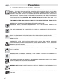
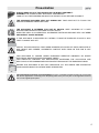
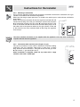
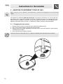
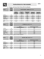
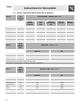
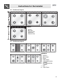
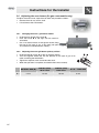
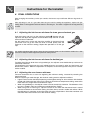
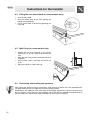
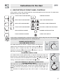
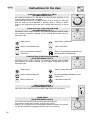
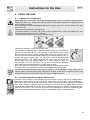
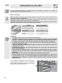
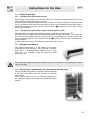
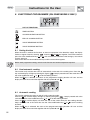
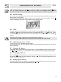
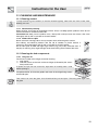
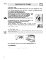
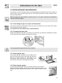
Table of Contents
1.
PRECAUTIONS FOR SAFETY AND USE______________________________________4
2.
INSTALLING THE APPLIANCE______________________________________________6
3.
ADAPTING TO DIFFERENT TYPES OF GAS _________________________________10
4.
FINAL OPERATIONS ____________________________________________________15
5.
DESCRIPTION OF FRONT PANEL CONTROLS _______________________________17
6.
USING THE HOB________________________________________________________19
7.
USING THE OVEN ______________________________________________________22
8.
ELECTRONIC PROGRAMMER (ON SOME MODELS ONLY) _____________________26
9.
DIGITAL TIMER (ON SOME MODELS ONLY) _________________________________28
10. ANALOGUE CLOCK (ON SOME MODELS ONLY) _____________________________28
11. CLEANING AND MAINTENANCE ___________________________________________29
12. EXTRAORDINARY MAINTENANCE _________________________________________31
THESE INSTRUCTIONS ONLY APPLY TO THE COUNTRIES OF DESTINATION WHOSE
IDENTIFICATION SYMBOLS ARE LISTED ON THE COVER OF THIS MANUAL.
INSTRUCTIONS FOR THE INSTALLER: these are intended for the qualified engineer who is to
check the gas supply system and install, commission and test the appliance.
INSTRUCTIONS FOR THE USER: these provide recommendations for use, a description of the
controls and the correct procedures for cleaning and maintaining the appliance.
3
Presentation
1. PRECAUTIONS FOR SAFETY AND USE
THIS MANUAL IS AN INTEGRAL PART OF THE APPLIANCE. TAKE GOOD CARE OF IT AND
KEEP IT TO HAND THROUGHOUT THE COOKER'S LIFE CYCLE. WE URGE YOU TO READ
THIS MANUAL AND ALL THE INFORMATION IT CONTAINS CAREFULLY BEFORE USING THE
COOKER. ALSO KEEP THE SET OF NOZZLES PROVIDED IN A SAFE PLACE. INSTALLATION
MUST BE CARRIED OUT BY QUALIFIED STAFF IN COMPLIANCE WITH THE RELEVANT
REGULATIONS. THIS APPLIANCE IS INTENDED FOR HOUSEHOLD USE AND COMPLIES WITH
THE EEC DIRECTIVES CURRENTLY IN FORCE. THE APPLIANCE IS BUILT TO PROVIDE THE
FOLLOWING FUNCTION: COOKING AND HEATING FOODS; ALL OTHER USES ARE TO BE
CONSIDERED IMPROPER.
THE MANUFACTURER DECLINES ALL LIABILITY FOR USES OTHER THAN THOSE STATED
ABOVE.
NEVER LEAVE PACKAGING RESIDUES UNATTENDED IN THE HOME.
SEPARATE WASTE PACKAGING MATERIALS BY TYPE AND CONSIGN THEM TO THE
NEAREST SEPARATE DISPOSAL CENTRE.
THE APPLIANCE MUST BE CONNECTED TO EARTH IN COMPLIANCE WITH ELECTRICAL
SYSTEM SAFETY REGULATIONS.
THE PLUG TO BE CONNECTED TO THE POWER SUPPLY LEAD AND THE RELATIVE SOCKET
MUST BE OF THE SAME TYPE AND COMPLY WITH THE RELEVANT REGULATIONS.
THE POWER SUPPLY SOCKET MUST BE ACCESSIBLE EVEN AFTER THE APPLIANCE HAS
BEEN BUILT-IN.
NEVER DISCONNECT THE PLUG BY PULLING ON THE POWER SUPPLY LEAD.
IMMEDIATELY AFTER INSTALLATION, CARRY OUT A QUICK TEST ON THE APPLIANCE
FOLLOWING THE INSTRUCTIONS PROVIDED LATER IN THIS MANUAL. IF THE APPLIANCE
FAILS TO OPERATE, DISCONNECT IT FROM THE ELECTRICAL MAINS AND CONTACT YOUR
NEAREST SERVICE CENTRE.
NEVER ATTEMPT TO REPAIR THE APPLIANCE.
AFTER EACH USE, ALWAYS CHECK THAT THE CONTROL KNOBS ARE TURNED TO THE
(OFF) POSITION.
NEVER PLACE INFLAMMABLE OBJECTS IN THE OVEN: IF IT SHOULD ACCIDENTALLY BE
SWITCHED ON, THIS MIGHT CAUSE A FIRE.
THE NAMEPLATE WITH THE TECHNICAL DATA, SERIAL NUMBER AND MARK IS IN A VISIBLE
POSITION INSIDE THE STORAGE COMPARTMENT.
THE NAMEPLATE MUST NEVER BE REMOVED.
NEVER PLACE PANS WITH BOTTOMS WHICH ARE NOT PERFECTLY FLAT AND SMOOTH ON
THE HOB PAN STANDS
NEVER USE PANS OR GRIDDLE PLATES WHICH PROJECT BEYOND THE OUTSIDE EDGE OF
THE HOB.
4
Presentation
ALWAYS KEEP HOLD OF THE HOB'S GLASS LID WHEN LOWERING IT.
WARNING: THE GLASS LID MAY SHATTER IF OVERHEATED.
TURN OFF ALL THE BURNERS AND WAIT FOR THEM TO COOL BEFORE CLOSING IT.
THE APPLIANCE BECOMES VERY HOT DURING USE. TAKE CARE NOT TO TOUCH THE
HEATING ELEMENTS INSIDE THE OVEN.
THE APPLIANCE IS INTENDED FOR USE BY ADULTS. KEEP CHILDREN AT A SAFE
DISTANCE AND NEVER ALLOW THEM TO PLAY WITH IT.
WHEN THE GRILL IS IN OPERATION, ACCESSIBLE PARTS MAY BECOME VERY HOT: KEEP
CHILDREN AT A SAFE DISTANCE.
IF THE APPLIANCE IS MOUNTED ON A STAND, IT MUST BE INSTALLED IN SUCH A WAY
THAT IT CANNOT SLIP OFF.
INSTALL THE APPLIANCE SO THAT WHEN DRAWERS OR DOORS OF UNITS INSTALLED AT
HOB HEIGHT ARE OPENED, ACCIDENTAL CONTACT WITH PANS ON THE HOB IS NOT
POSSIBLE.
THIS APPLIANCE IS TAGGED UNDER EUROPEAN DIRECTIVE 2002/96/EC ON WASTE
ELECTRICAL AND ELECTRONIC EQUIPMENT (WEEE).
THIS DIRECTIVE CONTAINS THE REGULATIONS GOVERNING THE COLLECTION AND
RECYCLING OF DECOMMISSIONED APPLIANCES THROUGHOUT THE EUROPEAN UNION.
BEFORE THE APPLIANCE IS PUT INTO OPERATION, ALL THE LABELS AND PROTECTIVE
FILMS APPLIED INSIDE OR OUTSIDE MUST BE REMOVED.
The manufacturer declines all responsibility for injury or damage caused by failure to comply with
the above regulations or deriving from tampering with even just one part of the appliance and the
use of non-original spare parts.
5
Instructions for the Installer
2. INSTALLING THE APPLIANCE
The appliance must be installed by a qualified engineer in compliance with the relevant regulations.
Depending on the type of installation, it is in class 1 (Fig. A) or class 2 - sub-class 1 (Fig.B-C).
It may be installed against walls one of which is higher than the worktop surface, at least 50 mm from
the side of the appliance, as shown in the installation class drawings A and B. Wall units or extractor
hoods installed above the appliance's work-top must be at least 750 mm above it.
A
Built-in Appliance
A
Built-in Appliance
B
Free-Standing Installation
B
Free-Standing Installation
C
Appliances with gas cylinder compartment and electric oven may only be installed in freestanding mode (see fig. B).
6
Instructions for the Installer
2.1 Electrical connection
Check that the voltage and size of the power supply line are as specified on the nameplate inside
the storage compartment.
This nameplate must never be removed.
If a permanent connection to the electrical mains is used, the appliance's power supply line must be
fitted with an omnipolar breaking device with contact breaking gap of at least 3 mm located in an
easily accessible position close to the appliance itself.
The mains connection may be permanent or by means of a plug and socket. If a plug and socket
connection is used, suitable cable compliant with the relevant standards must be used. For each
type of connection, the appliance must always be connected to earth. Before connecting it, check
that the power supply line is properly earthed. The use of reductions, adapters or junctions is not
recommended.
If the power supply cable has to be replaced, the gauge of the wires in
the new cable must be at least 1.5 mm2 (3 x 1.5 cable), bearing in
mind that the earth wire (yellow-green) must be at least 20 mm longer
at the end for connection to the appliance. For models with electric
plates, the cable must have cross-section of at least 2.5 mm2 (3 x 2.5
cable). The cable must be replaced by a qualified electrician, who
must make the mains connection as shown on the right.
L = brown
N = blue
= yellow-green.
2.2 Room ventilation
The appliance may only be installed in a permanently ventilated room as specified by the relevant
regulations. The air flow into the room where the appliance is installed must be sufficient for proper
gas combustion and room ventilation. The air intakes, protected by gratings, must be of suitable size
(see relevant regulations) and located so that they cannot be even partially obstructed.
The kitchen must be kept properly ventilated to disperse the heat and humidity produced by cooking
processes: in particular, a window should be opened or the speed of any fans increased after
prolonged use.
2.3 Combustion gas discharge
Combustion gases must be discharged by means of hoods connected to a flue with reliable natural
draught, or a fan extraction system. An effective extraction system requires careful design by an
authorised specialist, and must comply with the regulation distances and positions. After installation,
the engineer must issue a certificate of compliance.
7
Instructions for the Installer
2.4 Gas connection
2.4.1 Connection with rubber hose
When connecting with a rubber hose (which must be compliant with the relevant standards), ensure
that the total length of the pipeline is not more than 1.5 metres; also ensure that the hose does not
touch moving parts and is not crushed. The inside diameter of the hose must be 8 mm for BOTTLED
GAS and 13 mm for NATURAL GAS and TOWN GAS.
Check that all the conditions listed below are met:
• the hose must be fixed to the hose connector with a safety band clamp;
• the hose does not touch hot surfaces at any point (max. 50 °C);
• there are no traction forces or stresses acting on the hose and there are no tight bends or kinks
along its length;
• the hose does not touch sharp components or edges;
• if the hose is not perfectly gastight and causes gas leaks, do not attempt to repair it: replace it
with a new hose;
• check that the hose's expiration date, screen-printed on it, has not been passed.
CONNECTION USING RUBBER HOSES COMPLIANT WITH THE RELEVANT STANDARDS IS
ONLY PERMITTED IF THE HOSE IS ACCESSIBLE FOR INSPECTION ALONG ITS ENTIRE
LENGTH.
2.4.2 Natural and town gas connection
Make the connection to the gas main using a rubber hose compliant with the
specifications provided in the relevant standard (check that the hose is marked
with the code of this standard).
Screw the hose connector A on to the appliance's gas union B fitting the seal C
between them. Fit the hose D onto the hose connector A and secure it with the
band clamp E compliant with the relevant standards.
2.4.3
Connecting to the gas cylinder in the compartment inside the appliance (on some
models only)
Open the compartment in the side of the appliance
and place a gas cylinder of no more than 15 kg
inside. Fit one end of the hose onto the hose
connector and secure it with one of the two hose
clamps provided. Insert the hose into the gas
cylinder compartment through the hole on the rear of
the appliance, as shown on the right. Fit the other
end of the hose onto the gas cylinder pressure
regulator and secure it with the other hose clamp
provided. Check for any leaks with a soapy
solution, never with a naked light.
The connection between the cooker and the gas cylinder must be made using a piece of hose
compliant with the relevant standards and at least 1.4 m long.
8
Instructions for the Installer
2.4.4 Bottled gas connection
Use a pressure regulator complaint with the relevant standards and make the connection to the gas
cylinder in accordance with the relevant regulations.
Make sure that the gas supply pressure is as stated in the table in point "3.2/3.3 Burner and Nozzle
Data Tables".
Screw the small hose connector F onto the large hose connector A and
connect the resulting unit to the gas union B (or use the hose connector
G for connection straight to the gas union B) and fit the seal C. Fit the
ends of the rubber hose H onto the hose connector A+F (or G) and to
the outlet union of the pressure reducer on the gas cylinder. Fix the end
of the hose H to the hose connector A+F (or G) using the regulation
hose clamp I .
The hose connector G shown is not supplied with the appliance. Use only hose connectors
compliant with the relevant regulations.
2.4.5 Connection with steel hose (for all types of gas)
This type of connection can be made on both built-in and free-standing
appliances. Use only regulation steel hoses no more than 2 metres
long. Screw the end of the hose L , fitting the seal C, onto the gas union
B with external ½" gas thread (ISO 228-1).
When installation is complete, check for any leaks with a soapy
solution, never with a naked light.
9
Instructions for the Installer
3. ADAPTING TO DIFFERENT TYPES OF GAS
Before carrying out the operations described below, disconnect the appliance from the electricity
supply.
The appliance is tested with G20 (2H) natural gas at the pressure of 20 mbar. If it is to be used with
other types of gas, the burner nozzles have to be changed and the gas tap adjusted to set the
minimum flame. In addition, the primary air flow of the gas oven burner has to be adjusted (3.6.2
Adjusting oven burner primary air flow). To replace the nozzles, proceed as described below.
3.1 Changing the hob nozzles
1. Remove the pan stands, all the burner caps and the flame diffuser rings
2. Use a 7 mm socket wrench to unscrew the burner nozzles;
3. Replace the burner nozzles depending on the type of gas to be used (see point “3.2/3.3 Burner
and Nozzle Data Tables").
4. Put the burners back into place correctly.
Nozzles for the use of town gas (G110 – 8 mbar) are available from authorised service centres.
10
Instructions for the Installer
3.2 Burner and Nozzle Data Tables (50-60 cm Models)
Burner
Rated
heat
capacity
(kW)
BOTTLED GAS – G30/G31 30/37 mbar
Nozzle
diameter
1/100 mm
By-pass
mm
1/100
Reduced heat
capacity
(W)
Flow-rate
g/h G30
Flow-rate
g/h G31
Auxiliary
1.0
50
30
350
73
71
Semi-rapid
1.75
65
33
450
127
125
Rapid (3)
3.0
85
45
800
218
214
Rapid (5)
2.3
75
45
800
167
164
Triple Flame
3.2
91
65
1500
233
229
Oven
3.2
87
48
850
233
229
Grill
3.0
87
//
//
218
214
Burner
Rated
heat
capacity
(kW)
TOWN GAS – G110 8 mbar
Auxiliary
1.0
Nozzle
Diameter 1/100 mm
145
Reduced heat capacity
(W)
350
Semi-rapid
1.75
185
450
Rapid (3)
3.0
260
800
Rapid (5)
2.3
220
800
Triple Flame
3.3
290
1200
Oven
3.2
270
850
The data for town gas refer to category III 1a2H3+ appliances.
Burner
Rated
heat
capacity
(kW)
NATURAL GAS - G20 20 mbar
Auxiliary
1.0
Nozzle
Diameter 1/100 mm
72
Reduced heat capacity
(W)
350
Semi-rapid
1.75
97
450
Rapid (3)
3.0
115
800
Rapid (5)
2.3
103
800
Triple Flame
3.5
133
1500
Oven
3.2
130
850
Grill
3.0
130
//
11
Instructions for the Installer
3.3 Burner and Nozzle Data Tables (90 cm Models)
Burner
Auxiliary
Semi-rapid
Rapid
Triple Flame
Fish
Oven
Maxi oven
Grill
Maxi grill
Burner
Rated
heat
capacity
(kW)
1
1.75
3
3.2
1.9
3.2
5.2
2.9
4.0
Rated
heat
capacity
(kW)
BOTTLED GAS - G30/G31 30/37 mbar
Nozzle
diameter
1/100 mm
50
65
85
91
68
87
110
87
100
By-pass
mm
1/100
30
33
45
65
45
48
59
//
//
Auxiliary
Semi-rapid
Rapid
Triple Flame (4)
Triple Flame (8)
Fish
Oven
Maxi oven
Grill
Maxi grill
12
Rated
heat
capacity
(kW)
1
1.75
3
3.5
3.5
1.9
3.2
5.2
2.9
4.0
Flow-rate
g/h G30
Flow-rate
g/h G31
73
127
218
233
138
233
378
218
291
71
125
214
229
136
229
371
214
286
TOWN GAS – G110 8 mbar
Nozzle diameter
1/100 mm
Auxiliary
1
145
Semi-rapid
1.75
190
Rapid
3
260
Triple Flame
3.5
290
Fish
1.9
190
G110 gas cannot be used in models with gas oven.
The data for town gas refer to category III 1a2H3+ appliances.
Burner
Reduced
heat capacity
(W)
350
450
800
1500
800
850
1200
//
//
Reduced heat capacity
(W)
350
450
800
1500
800
NATURAL GAS - G20 20 mbar
Nozzle diameter
1/100 mm
72
97
115
133
140
94
130
164
130
150
Reduced heat capacity
(W)
350
450
800
1500
1500
800
850
1200
//
//
Instructions for the Installer
3.4 Hob burner layout
BURNERS
1.
2.
3.
4.
5.
Auxiliary
Semi-rapid
Rapid (60 x 60)
Triple Flame
Rapid (60 x 50)
3.5 Hob burner layout
BURNERS
1.
2.
3.
4.
5.
Auxiliary
Semi-rapid
Rapid
Triple Flame
Large electric plate
(1500W)
6. Small electric plate
(1000W)
7. Fish
8. Triple Flame
13
Instructions for the Installer
3.6 Adjusting the oven burner (for gas oven models only)
To adjust the oven burner, open the oven door and proceed as follows:
• Remove the oven tray and its shelf.
• Lift and extract the oven bottom.
3.6.1
•
•
•
Undo the oven burner fixing screw A.
Push the burner B to the right until the nozzle is
accessible.
Use a 13 socket wrench to change the nozzle, fitting
the one for the type of gas to be used (see point
“3.2/3.3 Burner and Nozzle Data Tables”).
3.6.2
•
•
•
•
X=
14
Changing the oven + grill burner nozzle
Adjusting the oven+grill burner primary air flow
Undo the adjuster screw "A" of the air regulator sleeve.
Turn the regulator sleeve "B" into the position for the type of gas to be
used, consulting the table below.
Tighten the adjuster screw and restore the seals.
When the operation is complete, reassemble the burner correctly.
NATURAL GAS (N)
G30/G31 (LPG)
90 cm Oven
G30/G31 (LPG)
60cm Oven
G 110 – TOWN GAS
5 mm
15 mm
10 mm
3 mm
Instructions for the Installer
4. FINAL OPERATIONS
After changing the nozzles, put the pan stands, the burner caps and flame diffuser rings back in
place.
After adjusting for use of a gas other than the gas used for testing the appliance, replace the gas
setting label on the appliance with the label for the new gas. The label is supplied in the bag with the
nozzles.
4.1 Adjusting the hob burner minimum for town gas and natural gas
Light the burner and turn it to the minimum setting . Remove the gas
tap knob and adjust the regulator screw beside the tap rod until an even
minimum flame is obtained.
Put the knob back in place and check the stability of the burner flame
(the flame must not go out when the knob is turned quickly from the
maximum to the minimum setting). Repeat the operation on all the gas
taps.
On models equipped with valves, keep the knob pressed down on the minimum setting for a few
seconds to keep the flame alight and prime the safety device.
4.2 Adjusting the hob burner minimum for bottled gas
To adjust the minimum level when using bottled gas, the adjuster screw beside the tap rod must be
turned fully clockwise.
The diameters of the bypasses for each individual burner are stated in point "3.2/3.3 Burner and
Nozzle Data Tables". When the adjustment is complete, re-seal the bypasses with paint or another
similar material.
4.3 Adjusting the oven burner minimum
The oven thermostat has a screw for regulating the minimum setting, accessed by removing the
thermostat knob.
When the type of gas used changes, the minimum setting must be adjusted as follows:
• Light the oven burner and keep it operating at the highest setting for 10/15 minutes with the door
closed and without the hob. Now turn the knob to the minimum temperature setting, remove the
knob and use a straight-head screwdriver to adjust.
• When using bottled gas, the adjuster screw must be turned fully clockwise. The diameter of the
by-pass is stated in point “3.2/3.3 Burner and Nozzle Data Tables”.
• When using town or natural gas, adjust the screw so that when the thermostat knob is turned
from the maximum to the minimum setting, the flame always remains stable and uniform. When
the adjustment is complete, re-seal the screw with paint or equivalents. Close the oven door and
check that the burner remains on at the minimum setting.
15
Instructions for the Installer
4.4 Fitting the rear splash-back (on some models only)
•
•
•
Unscrew the nuts B.
Place the splash-back on the hob, aligning the
rods C with the holes D.
Fix the splash-back to the hob by tightening the
screws A.
4.5 Wall fixing (on some models only)
•
•
•
•
Stretch out the chain attached to the cooker
horizontally so that the other end touches the
wall.
Mark the wall in the position where the hole is to
be drilled.
Drill the hole, insert a wall plug and attach the
chain.
Move the cooker up against the wall.
4.6 Positioning and levelling the appliance
After making the electrical and gas connections, level the oven by means of its four adjustable feet.
For good cooking results, the appliance must be properly levelled.
Depending on the model you have purchased, the foot height adjustment range may vary from 70 to
95 mm and from 110 to 160 mm. These heights refer to the distance between the highest point of
the foot (fixed part) and the lowest point (movable part which rests on the floor).
16
Instructions for the User
5. DESCRIPTION OF FRONT PANEL CONTROLS
All the cooker's control and monitoring devices are placed together on the front panel. The table below
provides the key to the symbols used.
FRONT RIGHT-HAND BURNER
CENTRAL BURNER
REAR RIGHT-HAND BURNER
GAS OVEN THERMOSTAT
REAR LEFT-HAND BURNER
ELECTRIC OVEN THERMOSTAT
FRONT LEFT-HAND BURNER
ELECTRIC OVEN FUNCTION KNOB
REAR CENTRAL BURNER
BURNER IGNITION BUTTON
FRONT CENTRAL BURNER
OVEN LIGHT SWITCH
If the cooker is equipped with an electronic programmer, before using the oven check that the
symbol appears on the display; see point “8.1 Setting the time".
BURNER IGNITION BUTTON
(ON SOME MODELS ONLY)
On models fitted with this button, to light the flame, turn the burner
ignition knob anti-clockwise to the minimum flame symbol
while
pressing it down. To adjust the flame, turn the knob to the zone
between the maximum
and the minimum
the burner, turn the knob to the
settings. To turn off
position.
HOB BURNER CONTROL KNOB
On models without burner ignition button, to light the flame press down the
knob and turn it anti-clockwise to the minimum flame setting
flame, turn the knob to the zone between the maximum
settings. To turn off the burner, turn the knob to the
. To adjust the
and the minimum
position.
GAS OVEN THERMOSTAT AND GRILL ELEMENT KNOB
(ON SOME MODELS ONLY)
This knob turns on the gas supply to light the burner inside the oven, or
operates the grill/rotisserie function. The gas oven cooking temperature is set
by turning the knob anti-clockwise to the value required, between Min. and
275°C.
For instructions for lighting the gas oven, refer to point “7.2 Using the gas
oven”.
17
Instructions for the User
ELECTRIC OVEN THERMOSTAT KNOB
(ON SOME MODELS ONLY)
The cooking temperature is selected by turning the knob clockwise to the
required setting, between 50° and 260°C.
The orange light comes on to indicate that the oven is heating up. This light
goes out when the set temperature is reached. When it flashes at regular
intervals, the temperature inside the oven is being kept constantly at the set
level.
STATIC ELECTRIC OVEN FUNCTION KNOB
(ON SOME MODELS ONLY)
The electric oven's various functions are suitable for different cooking modes.
After selecting the function required, set the cooking temperature using the
thermostat knob.
OVEN LIGHT
WIDE GRILL FUNCTION
STATIC OVEN FUNCTION
GRILL FUNCTION
BOTTOM HEATING ELEMENT
FUNCTION
GRILL + ROTISSERIE FUNCTION (ON
MODELS WITH ROTISSERIE)
FAN ELECTRIC OVEN FUNCTION KNOB
(ON SOME MODELS ONLY)
The electric oven's various functions are suitable for different cooking modes.
After selecting the function required, set the cooking temperature using the
thermostat knob.
OVEN LIGHT
GRILL + FAN FUNCTION
STATIC OVEN FUNCTION
BOTTOM HEATING ELEMENT + FAN
FUNCTION
GRILL FUNCTION
FAN OVEN FUNCTION
OVEN LIGHT SWITCH
(ON SOME MODELS ONLY)
This switch can be used to turn on the light inside the oven at any moment.
TIMER KNOB
(ON SOME MODELS ONLY)
To use the timer, set the buzzer by turning the knob clockwise.
The numbers correspond to minutes (maximum 55 minutes).
Setting is on a gradual scale and intermediate positions between the numbers
can be used. The end of cooking buzzer does not turn off the oven.
18
Instructions for the User
6. USING THE HOB
6.1 Lighting the hob burners
Before lighting the hob burners check that the flame diffuser rings are correctly in place with their
respective burner caps, making sure that the holes A in the flame diffusers are aligned with the
plugs and thermocouples.
Before lighting the burners lift the glass lid; before closing it again, turn off all the burners and wait
for them to cool.
The optional reducer B is for use with woks.
To prevent damage to the hob, the cooker comes complete with a raised pan stand C for use
underneath pans more than 26 cm in diameter.
The pan stand C supplied is for use even with small pans.
The burner it controls is shown next to each knob.
The appliance is equipped with an electronic ignition device. On some models,
simply press the knob and turn it anti-clockwise to the minimum flame symbol
, until the burner lights. If it does not light within the first 15 seconds, turn the
knob to 0 and wait at least 60 seconds before trying to light the burner again. In
models with burner ignition button, turn the knob as already described while
pressing the button. On models equipped with valves, once the burner has
ignited, keep the knob pressed down for a few seconds to allow the
thermocouple to heat up. The burner may go out when the knob is released:
this means that the thermocouple has not warmed up enough.
Wait a few moments and repeat the operation, keeping the knob pressed down
for longer. This is not necessary on burners not equipped with thermocouple.
On models with thermocouple, if the burners should go out accidentally a safety device will be
tripped, cutting off the gas supply even if the gas tap is open. In this case, turn the knob back to the
off position and wait at least 60 seconds before trying to relight the burner.
6.2 Practical hints for using the hob burners
For better burner efficiency and to minimise gas consumption, use pans with lids of suitable size for
the burner, so that flames do not reach up the sides of the pan (see point "6.3 Pan Diameters").
Once the contents come to the boil, turn down the flame far enough to prevent the liquid from boiling
over. When cooking, to prevent burns or damage to the hob all pans or griddle plates must be
placed inside the perimeter of the hob. All pans must have smooth, flat bottoms. Take the greatest
care when using fats or oils since they may catch fire if overheated. If the flame accidentally goes
out, turn off the control knob and wait at least 1 minute before trying to re-light the burner.
19
Instructions for the User
6.3 Pan diameters (60 cm Models)
BURNERS
(50 X 50)
min. and
max. Ø
(in cm.)
BURNERS
(60 X 60)
min. and
max. Ø
(in cm.)
1. Auxiliary
12 – 14
1. Auxiliary
12 – 14
2. Semi-rapid
16 – 22
2. Semi-rapid
16 – 24
3.
4.
5. Rapid
18 – 24
3. Rapid
18 – 26
4. Triple Flame
18 – 26
6.4 Pan diameters (90 cm Models)
BURNERS
1.
2.
3.
4.
7.
Auxiliary
Semi-rapid
Rapid
Triple Flame
Fish
8. Triple Flame
20
min. and max.
Ø (in cm.)
12 – 14
16 – 24
18 – 26
18 – 26
Special oval
pans
18 - 26
Instructions for the User
6.5 Switching on the electric plate
6.5.1 Switching on the electric plates
Cookers are equipped with plates of different diameters. They are controlled by a switch and are
turned on by turning the knob to the required setting. The front panel carries a screen-printed
diagram above each knob indicating the plate to which it refers. A yellow pilot light indicates that the
plate is on.
6.5.2 How to use the electric plates
Rapid plates offer the advantage of extremely fast cooking. The following is a guideline table of plate
settings.
RAPID PLATES
HEAT SETTING
COOKING OPERATIONS POSSIBLE
0
Off
-
1
Delicate
For melting butter, chocolate, etc.
For heating small amounts of liquid.
2
Gentle
For heating larger amounts of liquid.
3
Low
For defrosting frozen foods and braising, cooking
at or just below boiling point.
4
Medium
For cooking foods that have to be brought to the
boil, for roasting delicate meat and fish.
5
Strong
For roasts, cutlets, steaks and boiling large
pieces of meat.
6
Fierce
For bringing large amounts of water to the boil,
for frying.
ATTENTION
When the plate is switched on for the first time or has been out of use for a long
period, it should be dried by turning it on at setting 1 for 30 minutes, to eliminate
any moisture absorbed by the insulating material.
For correct use, follow these rules:
Do not switch the plate on until you have placed the pan on it.
• Use pans with thick, flat bottoms.
• Never use pans smaller than the plate.
• Dry the bottom of the pan before placing it on the plate.
• After use, to keep the electric plate in good condition and ensure its surface
remains clean and shining, it must be treated with the appropriate
commercial products. This necessary procedure prevents oxidation
(rusting).
• Never leave the appliance unattended when cooking easily flammable
foods containing oil and fat.
• The plates will remain hot even for a long time after use; do not touch them
with your hands or place anything on them to prevent the risk of burns.
• Before lighting the electric plates lift the glass lid of the cooker; before
closing it again, turn off all the plates and wait for them to cool.
• If you notice a crack in the surface of the plates, disconnect the appliance
from the electricity supply immediately and contact your nearest authorised
service centre.
21
Instructions for the User
7. USING THE OVEN
In models with electronic programmer, before using the oven, check that the display is showing the
symbol.
In models with analogue clock and timer knob, locate on the
symbol.
7.1 Precautions and General Advice
When the oven and grill are used for the first time, they should be heated to the maximum
temperature (260°C for electric oven and 275° for gas oven) for long enough to burn off any oily
residues left by the manufacturing process, which might contaminate foods with unpleasant smells.
After an interruption in the electricity supply, the programmer display flashes at regular intervals,
. For setting instructions, see point "8. ELECTRONIC PROGRAMMER”.
showing
Oven accessories which may come into contact with foods are made from materials compliant with
directive 89/109/EEC of 21/12/88 and relevant national regulations.
WARNING: the gas oven's door must be open when lit. The oven is fitted
with a safety system which cuts out burner ignition if the door is closed. If
you mistakenly attempt to light the burner with the door closed, open the
door and wait a few moments before trying again.
To avoid unpleasant contact with any steam inside the oven, open the door in
two stages: hold it half-open (about 5 cm) for 4-5 seconds, then open it
completely. If you have to carry out any procedures on foods, leave the door
open for as short a time as possible to prevent a drop in the oven temperature
which will impair the cooking results.
7.2 Using the gas oven
7.2.1 Lighting the burner by hand
Completely open the oven door and turn the thermostat knob anticlockwise. Place a lit match close to the end of the flame pipe A in the
centre of the bottom of the oven and press the thermostat knob. Once
the burner has ignited, keep the knob pressed down for a few seconds
to allow the thermocouple to heat up and check that the burner has lit
properly through the inspection hole B. The cooking temperature is set
by turning the knob clockwise to the value required, between 50° and
275°C.
If the burner accidentally goes out, turn the knob to the off ( )position and wait at least one minute
before trying to relight it.
22
Instructions for the User
7.3 Using the electric grill
7.3.1 Using the grill in cookers with electric oven
For short cooking procedures, such as final browning of cooked meat, select the static grill function
and turn the thermostat knob to the maximum temperature setting. The fan grill function (on
some models only) allows real cooking processes to be carried out, thanks to the forced fan system
that ensures the heat penetrates inside the food. For this type of cooking operation, select the fan
and use the function selector knob to set the ideal cooking temperature (in all cases
grill function
no more than 200°C).
7.3.2 Using the grill in cookers with gas oven
To activate this function, first turn off the oven burner by turning the knob back
to
and then turn the switch to .
WARNING: THE GAS OVEN AND THE GRILL/ROTISSERIE CANNOT BE
USED SIMULTANEOUSLY.
7.3.3 Operation of the grill + rotisserie
Both the static and the fan grill functions allow cooking in combination with the rotisserie. Fit the spit
or
grill function or the
rod into the rotisserie bushing, select the
the thermostat knob to the temperature required. (never exceed 200° C).
7.3.4
Using the rotisserie in cookers with maxi oven
Place the rotisserie shelf on the second pair
of runners from the bottom so that the rod
seat projects outside the oven. Place the rod
as shown in figure (1) and push the shelf into
the oven until the end of the rod reaches the
rotisserie motor hole. Now push the rotisserie
rod to the left until it is positioned as shown in
figure (2). To activate this function, press the
button.
These operations must be carried out with
the oven off and cold.
After cooking, use the tool provided to remove
the rod from the hole (3) and extract the shelf
to bring the rotisserie rod (4) out of the oven.
7.3.5
fan grill function and turn
1
2
3
4
Using the rotisserie in cookers with normal oven
Place the rotisserie shelf "B" on the second
pair of runners from the bottom and fit the rod
"A" into the hole in the back of the oven.
23
Instructions for the User
On some models the rotisserie is an optional and is not supplied as standard. It is available on
request from an Authorised Service Centre.
How to use the grill
When the oven has come on (the red light comes on to confirm this), leave it to heat up for 5
minutes before placing foods inside.
Seasonings should be added to foods before cooking. Foods should also be coated with oil or
melted butter before cooking. Use the oven tray to collect juice.
The foods for cooking must be placed on the oven shelf, which is then placed on one of the runners
fitted in the various types of ovens, following the guidelines below:
FOODS
Flat, thin pieces of meat
SHELF ON RUNNER
3
Rolled roasts
2–3
Poultry
2–3
ATTENTION
•
•
•
•
•
•
•
•
Grilling processes must never last more than 60 minutes.
In models with gas oven, the oven door must be half-open to the first catch during grill
and grill + rotisserie cooking operations. Fit the knob guard fitted into the runners
provided in the top of the oven to prevent the knobs and front panel from overheating.
In models with electric oven, the oven door must be closed during grill and grill +
rotisserie cooking operations.
To prevent hazardous overheating, the appliance's glass lid must always be raised when
using the oven or grill.
Accessible parts may be very hot during and after use of the grill; keep children well
away from the appliance.
During rotisserie cooking operations, one of the pans supplied with the cooker should be
placed on the bottom of the oven, on the bottom runners, to collect any grease and fat
produced.
When using the oven, remove all unused pans and shelves from its interior.
During cooking, do not cover the bottom of the oven with aluminium or tin foil, and do
not place pans or trays on it; this may damage the enamel coating. If you wish to use
greaseproof paper, position it so that it does not interfere with the hot air circulation
inside the oven.
If your cooker is equipped with knob guard bar,
when cooking using the grill or grill + rotisserie it
must be fitted as shown here, fitting the rods “B” into
the slots “A” in the top of the oven.
24
Instructions for the User
7.4 Using the gas grill
7.4.1
Lighting the gas grill burner by hand
After opening the oven door, press the knob and turn it clockwise to the grill setting
and use a
match to light the burner on the top of the oven.
Once the burner has ignited, keep the knob pressed down for about 10 seconds. If the burner does
not stay on after this time, release the knob and wait at least 1 minute before trying to light it again. If
the burner accidentally goes out, turn the knob to the off ( ) position and wait at least 1 minute
before trying to relight it.
7.4.2
Lighting the gas grill burner using the electric ignition system
After opening the oven door, press the knob and turn it clockwise to the grill setting .
Once the burner has ignited, keep the knob pressed down for about 10 seconds. If the burner has
not lit after this time, release the knob and wait at least 1 minute before trying to light it again. If the
burner accidentally goes out, turn the knob to the off ( ) position and wait at least 1 minute before
trying to relight it.
In case of electricity blackout, the burner can always be lit with a match.
7.5 Storage compartment
The storage compartment is in the bottom of the cooker,
underneath the oven. To open it, pull on the top of the door.
Never use it to store flammable materials such as rags,
paper, etc.; it is intended to take the appliance's metal
accessories only.
Never open the storage compartment when the oven is on and still hot. The temperatures inside it
may be very high.
7.6 Gas cylinder compartment (for the relevant models only)
The gas cylinder compartment, accessed by opening the door
in the side of the cooker, can also be used as a storage
compartment.
The 3 shelves shown here are not standard equipment but
are available as optional accessories from Authorised Service
Centres.
25
Instructions for the User
8. ELECTRONIC PROGRAMMER (ON SOME MODELS ONLY)
LIST OF FUNCTIONS
TIMER BUTTON
COOKING DURATION BUTTON
END OF COOKING BUTTON
VALUE DECREASE BUTTON
VALUE INCREASE BUTTON
8.1 Setting the time
When the oven is used for the first time, or after an interruption in the electricity supply, the display
flashes at regular intervals, showing
. Press the
and
keys together, and at the same time
press the value modification keys
or : this will increase or decrease the setting by one minute
for each pressure.
Press one of the two value modification keys until the current time appears.
Before each programmer setting, switch on the function and set the temperature required.
8.2 Semiautomatic cooking
This function only switches the oven off automatically at the end of the cooking time. Press the
key and the display will light up showing the figures
; keep it pressed and at the same time use
the value modification keys
or
to set the cooking duration.
When the
key is released, the count of the programmed cooking duration will start and the
display will show the current time together with the symbols A and .
8.3 Automatic cooking
This function switches the oven on and off in fully automatic mode.
Press the
key and the display will light up showing the figures
; keep it pressed and at the
same time use the value modification keys
or
to set the cooking duration.
Press the
key and the display will show the sum of the current time plus the cooking duration:
keep it pressed, and at the same time use the value modification keys
or
to set the cooking
end time.
When the
key is released, the count of the programmed cooking duration will start and the
display will show the current time together with the symbols A and
.
26
Instructions for the User
After making the setting, press the
key to view the cooking time remaining; press the key to
view the cooking end time. The logic prevents the setting of incompatible values (e.g. the
programmer will not accept a cooking end time with a duration which is too long for this value).
8.4 End of cooking
At the end of the cooking time the oven will switch off automatically and simultaneously a buzzer will
start to sound in on-off mode.
After the buzzer is stopped, the display will return to showing the current time together with the
symbol, indicating that the oven is again ready for use in manual mode.
8.5 Timer
The programmer can also be used as an ordinary timer. Press the
key and the display will show
the figures
; keep it pressed and press the value modification keys
or . When the
key
is released the programmed count will start and the display will show the current time and the
symbol.
After making the setting, to display the time remaining press the
key.
In timer mode, the system will not cut out operation of the oven at the end of the set time.
8.6 Adjusting the buzzer volume
The acoustic alarm has 3 different volume settings.
To change the setting, press the
key at the end of the minute counter function with the buzzer
alarm in operation.
8.7 Stopping the buzzer
The buzzer stops automatically after seven minutes. It can be stopped in manual mode by pressing
the
and
keys together. To switch off the oven, then return all the knobs to the 0 setting.
8.8 Deleting the data set
With the program set, keep the key of the function for deletion depressed and at the same time scroll
to the value
using the value modification keys
or . The timer will interpret deletion of the
duration as the end of cooking.
8.9 Modifying the data set
The cooking data set can be modified at any moment by keeping the key of the function pressed and
at the same time pressing the value modification keys
or .
27
Instructions for the User
9. DIGITAL TIMER (ON SOME MODELS ONLY)
This device sounds an on-off buzzer at the end of the set cooking time. It therefore offers timer
functions only, and is not a programmer.
LIST OF FUNCTIONS
TIME SETTING BUTTON
VALUE DECREASE BUTTON
VALUE INCREASE BUTTON
9.1.1 Setting the time
When the oven is used for the first time, or after an interruption in the electricity supply, the display
. Press the
key and use the
or
keys to set the
flashes at regular intervals, showing
current time.
9.1.2 Setting the timer
key and keep it pressed until the minutes required appear. About 5
To set the timer, press the
seconds after the
key is released, the countdown will start; when it finishes, the buzzer will sound
in on-off mode.
symbol will appear on the display and when the
key is pressed the
During the countdown, the
current time is displayed for 5 seconds.
9.1.3
Stopping the buzzer
The buzzer stops automatically after seven minutes. It can be stopped in manual mode by pressing
the
key.
9.1.4
Adjusting the buzzer volume
The buzzer volume can be varied (3 settings) while it is in operation by pressing the
9.1.5
Modifying the data set
The timer data set can be modified at any moment by pressing the
or
keys.
10. ANALOGUE CLOCK (ON SOME MODELS ONLY)
To set the mechanical timer, turn the knob clockwise.
The setting range is from 0 to 55 minutes. At the end of the cooking time, a
buzzer will sound; to stop it use the knob to turn the outside sector to the
setting.
To set the clock, pull the knob and turn it clockwise.
28
key.
Instructions for the User
11. CLEANING AND MAINTENANCE
11.1 Cleaning enamel
To keep enamel in good condition, it must be cleaned regularly, after each use of the cooker, after
allowing it to cool.
11.1.1 Routine daily cleaning
When cleaning and caring for enamelled surfaces always use only specific products which do not
contain abrasives or chlorine-based acids.
Instructions for use: pour the product onto a damp cloth and wipe over the surface, then rinse
thoroughly and dry with a soft cloth or chamois leather.
11.1.2 Food stains or spills
Never use metal scouring pads or sharp scrapers which will damage the surface.
Use ordinary non-abrasive products with the aid of wooden or plastic utensils if
necessary. Rinse thoroughly and dry with a soft cloth or chamois leather.
Do not allow spills of foods with high sugar content (e.g. jam) to dry inside the oven. If
they dry for too long, they might damage the enamel coating of the inside of the oven.
11.2 Cleaning the hob components
11.2.1 The glass lid
The lid can be taken off its hinges for easier cleaning.
1- open the lid;
2- undo the screws on the back of the two hinges (indicated by the arrows
here) and lift it off.
If liquids are spilt onto the closed lid, wipe them off carefully with a cloth
before opening it.
To replace the lid, fit it into the guides and screw in the hinge fixing screws
with the lid open.
Take care not to touch the glass of the lid with still-hot pots and pans. The strong heat might crack
the glass
29
Instructions for the User
11.2.2 The pan stands
Remove the pan stands and wash them in warm water with a non-abrasive detergent, taking care to
remove all deposits. Put them back on the hob.
The continuous contact between the pan stands and the flame may cause deterioration in the
enamel in the areas exposed to heat over time. This is an absolutely natural phenomenon which
does not impair this component's operation at all.
11.2.3 The burner caps and flame diffuser rings
The burner caps and flame diffuser rings can be removed for easier
cleaning; wash them in hot water and non-abrasive detergent, taking
care to remove all deposits, and wait for them to dry completely.
WARNING: never wash these components in the dishwasher.
They may be left to soak in hot water and detergent.
Replace the flame diffuser rings, checking that they are correctly in place
with their respective burner caps, making sure that the holes A in the
flame diffusers are aligned with the plugs and thermocouples.
11.2.4 The plugs and thermocouples
For best performance, on the relevant models the ignition plugs and
thermocouples must always be kept thoroughly clean. Check them frequently
and if necessary clean them with a wet cloth. Remove any dry residues with a
wooden toothpick or a needle.
11.3 Cleaning the oven
To keep the oven in good condition, it must be cleaned regularly, after allowing it to cool down.
Remove all removable parts.
Clean the oven shelves with hot water and non-abrasive detergents, rinse and dry.
11.4 Door glazing
The glass in the door should always be kept thoroughly clean. Use absorbent kitchen roll; remove
stubborn dirt with a damp sponge and ordinary detergent.
30
Instructions for the User
12. EXTRAORDINARY MAINTENANCE
Occasionally, the oven will require minor servicing procedures or the replacement of parts subject to
wear and tear, such as gaskets, light bulbs, etc. The specific operations for each procedure of this
kind are provided below.
Before carrying out any operation involving access to live parts, disconnect the appliance
from the electricity supply.
12.1 Lubricating the gas oven taps and thermostat
Over time, the gas taps and thermostat of the gas oven may become stiff or jam. Clean their insides
and change their lubricating grease.
This operation must be carried out by a skilled technician.
12.2 Changing the light bulb
Remove the protective cover A by unscrewing it anti-clockwise and replace the bulb B with another
of the same type (25 W). Replace the protective cover A.
Use only light bulbs approved for ovens (T 300°C).
12.3 Removing the door
Lift the levers B and take hold of the two sides of the
door with both hands close to the hinges A. Raise the
door to an angle of about 45° and remove it. To
reassemble, fit the hinges A into their grooves, then
lower the door into place and engage the levers B.
12.4 Removing the gasket
To allow thorough cleaning of the oven, the door gasket can be removed.
Before removing the gasket, remove the oven door as described above. Once
the door has been removed, lift the tangs at the corners as shown on the
right.
31