1
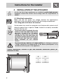
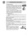
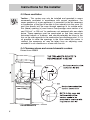
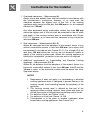
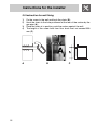
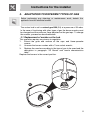
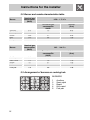
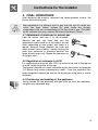
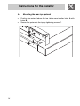
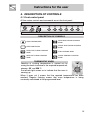
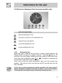
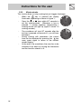
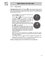
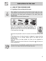
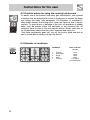
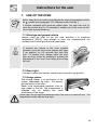
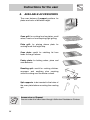
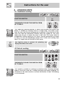
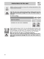
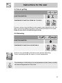
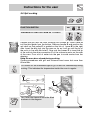
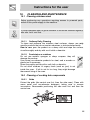
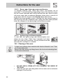
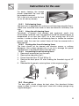
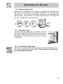
Contents
1.
INSTRUCTIONS FOR SAFE AND PROPER USE________________ 4
2.
INSTALLATION OF THE APPLIANCE_________________________ 6
3.
ADAPTATION TO DIFFERENT TYPES OF GAS _______________ 11
4.
FINAL OPERATIONS _____________________________________ 13
5.
DESCRIPTION OF CONTROLS ____________________________ 15
6.
USE OF THE COOKING HOB ______________________________ 21
7.
USE OF THE OVEN ______________________________________ 23
8.
AVAILABLE ACCESSORIES _______________________________ 24
9.
COOKING HINTS ________________________________________ 25
10.
CLEANING AND MAINTENANCE ___________________________ 29
11.
EXTRAORDINARY MAINTENANCE _________________________ 32
THESE INSTRUCTIONS ARE VALID ONLY FOR END USER COUNTRIES WHOSE
IDENTIFICATION SYMBOLS APPEAR ON THE COVER OF THIS MANUAL.
INSTRUCTIONS FOR THE INSTALLER: these are for the qualified
technician who must carry out a suitable check of the gas system,
install the appliance, set it functioning and carry out an inspection test.
INSTRUCTIONS FOR THE USER: these contain user advice,
description of the commands and the correct procedures for cleaning
and maintenance of the appliance.
3
Introduction
1. INSTRUCTIONS FOR SAFE AND PROPER USE
THIS MANUAL IS AN INTEGRAL PART OF THE APPLIANCE AND
THEREFORE MUST BE KEPT IN ITS ENTIRETY AND IN AN ACCESSIBLE
PLACE FOR THE WHOLE WORKING LIFE OF THE COOKER. WE ADVISE
READING THIS MANUAL AND ALL THE INSTRUCTIONS THEREIN BEFORE
USING THE COOKER. ALSO KEEP THE SERIES OF NOZZLES SUPPLIED.
INSTALLATION MUST BE CARRIED OUT BY QUALIFIED PERSONNEL IN
ACCORDANCE WITH THE REGULATIONS IN FORCE. THIS APPLIANCE IS
INTENDED FOR DOMESTIC USES AND CONFORMS TO CURRENT
REGULATIONS IN FORCE. THE APPLIANCE HAS BEEN BUILT TO CARRY
OUT THE FOLLOWING FUNCTIONS: COOKING AND HEATING-UP OF FOOD.
ALL OTHER USES ARE CONSIDERED IMPROPER.
THE MANUFACTURER DECLINES ALL RESPONSIBILITY FOR IMPROPER
USE.
DO NOT LEAVE THE PACKING IN THE HOME ENVIRONMENT. SEPARATE
THE VARIOUS WASTE MATERIALS AND TAKE THEM TO THE NEAREST
SPECIAL GARBAGE COLLECTION CENTRE.
IT IS OBLIGATORY FOR THE ELECTRICAL SYSTEM TO BE GROUNDED
ACCORDING TO THE METHODS REQUIRED BY SAFETY RULES.
IMMEDIATELY AFTER INSTALLATION CARRY OUT A BRIEF INSPECTION
TEST OF THE APPLIANCE, FOLLOWING THE INSTRUCTIONS BELOW.
SHOULD THE APPLIANCE NOT FUNCTION, DISCONNECT IT FROM THE
SUPPLY AND CALL THE NEAREST TECHNICAL ASSISTANCE CENTRE.
NEVER ATTEMPT TO REPAIR THE APPLIANCE.
ALWAYS CHECK THAT THE CONTROL KNOBS ARE IN THE POSITION
"ZERO" (OFF) WHEN YOU FINISH USING THE HOB.
NEVER PUT INFLAMMABLE OBJECTS IN THE OVEN: THEY COULD BE
ACCIDENTALLY LIGHTED AND CAUSE FIRES.
DURING USE THE APPLIANCE BECOMES VERY HOT. TAKE CARE NOT TO
TOUCH THE HEATING ELEMENTS INSIDE THE OVEN.
4
Introduction
DO NOT INSTALL THIS APPLIANCE ON A RAISED PLATFORM.
THE I.D. PLATE WITH TECHNICAL DATA, REGISTRATION NUMBER AND
BRAND NAME IS POSITIONED VISIBLY IN THE STORAGE COMPARTMENT.
THE PLATE MUST NOT BE REMOVED.
DO NOT PUT PANS WITHOUT PERFECTLY SMOOTH AND FLAT BOTTOMS
ON THE COOKING HOB GRIDS.
NEVER USE THE COOKING HOB AS A WORK SURFACE.
DO NOT SPRAY AEROSOLS IN THE VICINITY OF THIS APPLIANCE WHILE IT
IS IN OPERATION.
WHERE THIS APPLIANCE IS INSTALLED IN MARINE CRAFT OR IN
CARAVANS, IT SHALL NOT BE USED AS A SPACE HEATER.
DO NOT USE CONTAINERS OR BROILERS THAT EXTEND BEYOND THE
OUTER PERIMETER OF THE HOB.
THE APPLIANCE IS DESIGNED FOR USE BY ADULTS. DO NOT ALLOW
CHILDREN TO GO NEAR OR PLAY WITH IT.
BEFORE THE APPLIANCE IS PUT INTO OPERATION, ALL THE LABELS AND
PROTECTIVE FILMS APPLIED INSIDE OR OUTSIDE MUST BE REMOVED.
The manufacturer declines all responsibility for damage to persons
or things caused by non-observance of the above prescriptions or by
interference with any part of the appliance or by the use of non-original
spares.
5
Instructions for the installer
2. INSTALLATION OF THE APPLIANCE
It is the law that all gas appliances are installed by authorised persons.
Clearance around the cooker must comply with the requirements of
AS5601.
2.1 Electrical connection
Make sure that the power line voltage matches the specifications
indicated on the rating plate located inside the storage compartment.
This rating plate must never be removed.
On the power line, install an omnipolar cut-off device with contact cut-off
distance greater than or equal to 3 mm, located in an easily accessible
position near the unit.
If the power cable is replaced, the wire
section on the new2 cable must not be
less than 1.5 mm (3 x 1.5 cable),
keeping in mind that the end to be
connected to the hob must have the
ground wire (yellow-green) longer by at
least 20 mm. Use only the special
cables available at our Service
Centres.
The manufacturer declines all responsibility for damage to persons
or things caused by non-observance of the above prescriptions or by
interference with any part of the appliance.
Overall dimensions: location of gas and electrical connection points (all
measures in mm).
6
A
110
B
760
C
150
D
170
Instructions for the installer
2.2 Gas connection
This appliance is suitable for installation with Natural
Gas or LPG (propane). Refer to page 12 for the relevant
burner pressure and appropriate injector sizes. When
the appliance is to be connected to Natural Gas then the
pressure regulator supplied must be fitted to the gas
inlet. A test point (for checking the gas pressure) is
supplied either with the regulator or as a separate fitting
in the case of LPG (propane) appliances.
Connection of the appliance to the gas supply must be in
accordance with the requirements of AS5601. A ½” BSP
connector at the inlet is recommended and the gas
supply line to the appliance must be of adequate length
to allow sufficient withdrawal of appliance for service or
disconnection and be:
1. annealed copper pipe or;
2. flexible hose according to AS/NZ1869 & be at least Class “B”, 10 mm
diameter.
The appliance must be installed with provision to allow the gas to be
turned off and disconnected for servicing and removal of the appliance as
required from the gas supply.
Before the appliance is operated make certain all relevant parts are placed
in the correct position.
When the installation is completed the installation connections of
appliance will require to be leak tested, the burner operating pressure and
flame checked and adjusted.
Warranty service calls do not cover these adjustments!
To check the operating pressure of the appliance it is recommended at
least 2 large size burners are used. Ensure appliance is secured to wall
when installation is completed.
N.G. The regulator supplied must be fitted to the ½ BSP thread at the rear
of the appliance. An approved manual shut-off valve must be installed.
The N.G. regulator must be checked and adjusted to 1.0kPa after
installation.
ULPG: Can be connected to the inlet fitting
directly. The pressure must be checked to
ensure it is operating at 2.75kPa. A separate
test point fitting must be installed between the
piping & the appliance for the pressure to be
checked to ensure it is operating at 2.75kPa.
7
Instructions for the installer
2.3 Room ventilation
Caution – This cooker may only be installed and operated in rooms
permanently ventilated in accordance with current regulations. For
proper operation of a gas appliance it is essential for the air necessary
for combustion of the gas to be able to flow naturally into the room. Air
must flow directly into the room through openings in its outside walls.
This (these) opening (s) must have a free passage cross-section of at
least 100 cm2, or 200 cm2 for appliances not equipped with gas safety
device. These openings must be constructed so that they cannot be
obstructed indoors or outdoors, and should preferably be close to the
floor on the side opposite to the combustion gas discharge point. If it is
not possible to make the openings in the room where the cooker is
installed, the necessary air may be taken from an adjoining room,
proveded it is not a bedroom or a room with fire risk.
2.4 Clearance above and around domestic cookers
Extract from AS5601
REQUIREMENTS
8
Instructions for the installer
1
Overhead clearances – (Measurement A)
Range hoods and exhaust fans shall be installed in accordance with
the manufacturer’s instructions. However, in no case shall the
clearance between the highest part of the hob of the cooking
appliance and a range hood be less than 600 mm or, for an overhead
exhaust fan, 750 mm.
Any other downward facing combustible surface less than 600 mm
above the highest part of the hob shall be protected for the full width
and depth of the cooking surface area in accordance with Clause
5.12.1.2. However, in no case shall this clearance to any surface be
less than 450 mm.
2
Side clearances – (Measurements B & C)
Where B, measured from the periphery of the nearest burner to any
vertical combustible surface, is less than 200 mm, the surface shall
be protected in accordance with Clause 5.12.1.2 to a height C of not
less than 150 mm above the hob for the full dimension (width or
depth) of the cooking surface area. Where the cooking appliance is
fitted with a ‘splashback’, protection of the rear wall is not required.
3
Additional requirements for Freestanding and Elevated Cooking
Appliaces – (Measurements D & E)
Where D, the distance from the periphery of the nearest burner to a
horizontal combustible surface is less than 200 mm, then E shall be
10 mm or more, or the horizontal surface shall be above the trivet.
See insets above.
NOTES
1
2
3
4
5
Requirement 3 does not apply to a freestanding or elevated
cooking appliance which is designed to prevent flames or the
cooking vessels from extending beyond the periphery of the
appliance.
The ‘cooking surface area’ is defined as that part of the
appliance where cooking normally takes place and does not
include those parts of the appliance containing control knobs.
For definition of hob, see Clause 1.4.64.
For definition of trivet, see Clause 1.4.109.
Consideration is to be given to window treatments when
located near cooking appliances. See Clause 5.3.4.
9
Instructions for the installer
2.5 Instruction for wall fixing
1)
2)
3)
4)
A
10
Fix the screw to the wall and hook the chain (B);
Hook the chain to the hole positioned at the rear of the cooker by the
gas pipe (A);
Once the chain is in position, push the cooker against the wall;
The height of the screw hole from floor level must not exceed 800
mm (C).
B
C
Instructions for the installer
3. ADAPTATION TO DIFFERENT TYPES OF GAS
Before performing any cleaning or maintenance work, detach the
appliance from the electrical socket.
The cooker hob is set for natural gas G20 (2H) at a pressure of 20 mbar.
In the case of functioning with other types of gas the burner nozzles must
be changed and the minimum flame adjusted on the gas taps. To change
the nozzles, proceed as described below.
3.1 Replacement of nozzles on the hob
This operation requires no primary air regulation.
1.
Extract the grids and remove all the caps and flame-spreader
crowns;
2.
Unscrew the burner nozzles with a 7 mm socket wrench;
3.
Replace the nozzles according to the type of gas to be used and the
description in paragraph “3.2 Burner and nozzle characteristics
table”.
Replace the burners in the correct position.
11
Instructions for the installer
3.2 Burner and nozzle characteristics table
Burner
Auxiliary
Semi-rapid
Rapid
Wok
Fish pan
Burner
Auxiliary
Semi-rapid
Rapid
Wok
Fish pan
Nominal gas
consumption
(MJ/h)
3.9
6.3
10.8
13.5
6.8
LPG – 2.75 kPa
Turn-down gas
consumption
(MJ/h)
1.3
1.6
2.7
5.8
2.9
Nominal gas
consumption
(MJ/h)
3.9
7.5
12
15
7.8
Injector
(mm)
0.54
0.68
0.88
1.00
0.72
NG – 1.00 kPa
Turn-down gas
consumption
(MJ/h)
1.3
1.6
2.7
5.8
2.9
Injector
(mm)
0.90
1.20
1.55
1.75
1.26
3.3 Arrangement of burners on cooking hob
BURNERS
1
2
3
4
5
12
Auxiliary
Semi rapid
Rapid
Ultra rapid
Fish pan
Instructions for the installer
4. FINAL OPERATIONS
After replacing the nozzles, reposition the flame-spreader crowns, the
burner caps and the grids.
After adjustment to a different kind of gas from the one for which the
cooker has been tested, replace the plate inside the storage
compartment with one corresponding to the new kind of gas. This plate
can be obtained from your nearest Authorised Assistance Centre.
4.1 Adjustment of minimum for natural gas
Light the burner and take it to the minimum.
Remove the gas tap knob and turn the
adjustment screw inside or at the side of the tap
shaft (depending on the model) until there is a
regular minimum flame. Replace the knob and
check burner flame stability: (rapidly turning the
knob from maximum to minimum position, the
flame should not go out). Repeat the operation on
all the gas taps.
4.2 Regulation of minimum for LPG
For regulating the minimum with LPG, the screw at the side of the tap rod
must be turned clockwise all the way.
The bypass diameters for each individual burner are shown in paragraph
“3.2 Burner and nozzle characteristics table”. Once the regulation has
been completed, replace the seal on the by-passes using paint or similar
materials.
4.3 Positioning and levelling of the appliance
Having carried out the electricity and gas hook-up, level the appliance
using the four adjustable legs.
13
Instructions for the installer
4.4
•
•
14
Mounting the rear top upstand
Position the upstand above the top, taking care to align holes A with
holes B.
Secure the upstand to the top by tightening screws C.
Instructions for the user
5. DESCRIPTION OF CONTROLS
5.1 Front control panel
All the cooker controls and commands are on the front panel.
DESCRIPTION OF SYMBOLS
OVEN THERMOSTAT
REAR RIGHT-HAND COOKING
ZONE
OVEN FUNCTIONS
FRONT RIGHT-HAND COOKING
ZONE
FRONT LEFT-HAND COOKING
ZONE
FISH COOKING ZONE
REAR LEFT-HAND COOKING
ZONE
FRONT CENTRAL COOKING
ZONE
THERMOSTAT KNOB
Selection of cooking temperature is carried out by
turning the knob clockwise to the required temperature,
between 50° and 250°C.
The tell-tale light comes on to indicate that the oven is
warming up.
When it goes out it means that the required temperature has been
reached. Regular flashing means that oven temperature is being
constantly maintained at the programmed level.
15
Instructions for the user
FUNCTION SWITCH KNOB
Turn the knob to select from the following functions:
NO FUNCTION SET
UPPER AND LOWER
HEATING ELEMENT
UPPER AND LOWER
HEATING ELEMENT +
VENTILATION
GRILL ELEMENT
LOWER HEATING ELEMENT
+
VENTILATION
LOWER HEATING ELEMENT
+
VENTILATED HEATING ELEM.
VENTILATED HEATING
ELEMENT + VENTILATION
DEFROSTING
GRILL ELEMENT +
VENTILATION
COOKING HOB BURNER
COMMAND KNOB
To light the flame, press and turn the knob anticlockwise
to the large flame symbol. Adjust the flame by turning
the knob to the area comprised between maximum and
minimum marks. To turn off, set the knob to either
"zero".
16
Instructions for the user
5.2 Electronic Analogue Clock (on some models only)
LIST OF FUNCTIONS
MINUTE-MINDER BUTTON
AUTOMATIC SWITCH-OFF TIMING BUTTON
TIME SETTING AND RESET
VALUE DECREASE BUTTON
VALUE INCREASE BUTTON
5.2.1
Setting the time
When the oven is used for the first time, or after a power blackout, the
display flashes on and off at regular intervals. Press the
key for 1/2
seconds to stop the display flashing and start setting of the current time.
Press the value modification keys
or
to increase or decrease by
one minute for each time a key is pressed.
Press one of the two value modification keys until the current time
appears. The clock will start from the time set 6/7 seconds after the last
key is pressed.
At the end of each programmed cooking operation, the clock gives 8
beeps, repeated 3/4 times at intervals of about 1 and a half minutes.
The beeps can be stopped at any moment by pressing any key.
17
Instructions for the user
5.2.2
Minute-minder
This function does not stop cooking but just triggers the beeps.
-
When the
key is pressed the display
illuminates, appearing as shown in figure 1;
-
Press the
or
keys within 6/7 seconds to
set the minute-minder. Whenever a key is
pressed, 1 outside segment, representing 1
cooking minute will light up (figure 2 shows 10
cooking minutes).
The countdown will start 6/7 seconds after the
last key is pressed; at the end of it, you will hear
the beeps.
During cooking with countdown, the current
time can be displayed by pressing the
key
once; press again to return to the minuteminder display.
At the end of the countdown, the oven has to be
switched off by hand, by turning the thermostat
and the function selector to 0.
-
-
18
1
2
Instructions for the user
5.2.3
Programming
Cooking duration time: the 2nd button
can be used to set the cooking
time. Before setting it, turn the thermostat to the cooking temperature of
choice and the function selector knob to any setting. To set the cooking
time, proceed as follows:
-
Press the
key for 1/2 seconds; the pointer will
move to position 12 (Fig. 1).
-
Use the
-
-
-
and
keys to set the cooking time;
whenever the
key is pressed, 1 minute will
be added to the cooking time, and every 12
1
minutes a new inside segment will light up
(figure 2 shows a cooking time of 1 hour).
Once the required time has been set, cooking
will start about 6 seconds after the last time the
or . key is pressed.
Once cooking has started, the display will show
the current time, represented by the constantly
2
on segments, and the minutes left until cooking
finishes, represented by the flashing segments
(every flashing segments indicates 12 minutes of
cooking time left).
When the end of the cooking time is reached, the timer will switch
off the oven heating elements, the beeps will start and the numbers
on the dial will flash.
The cooking time can also be reset by deleting the program set;
pressing the central key
for 1 or 2 seconds will delete the time
set and the oven will have to be switched off by hand.
Caution: cooking times of more than 6 hours cannot be set.
19
Instructions for the user
Cooking start: as well as setting a cooking duration time, the user can
also set the cooking start time (up to 12 hours after the current time). To
set the cooking start/end time, proceed as follows.
-
Set the cooking duration time as described in the previous point.
-
Within 6/7 seconds after the last time the
or
keys are
pressed, press the
key to set the cooking start time. The display
will show the current time with the inside segments indicating the
cooking end time illuminated. Use the
and
keys to set the
cooking start time.
6/7 seconds after the last time a key is pressed, the display will
show the current time and the cooking start and end times, indicated
by the illuminated inside segments. The segments on the display
will be constantly on until the current time is the same as the
cooking start time; as soon as the current time reaches the cooking
start time set, all the inside segments will start to flash, indicating
that the oven has started cooking.
When the end of the cooking time is reached, the timer will switch
off the oven heating elements, the beeps will start and the numbers
on the dial will flash.
To reset the entire program set, keep the central key
pressed for
1 or 2 seconds: if cooking has already started the oven will have to
be switched off by hand.
The image on the right shows an example of
programming: the current time is 7.06 and
cooking is programmed to start at 8 o'clock
and finish at 9.
At 8 o'clock, the inside segments between 8
and 9 will start to flash and the hour pointer will
remain still.
Caution: for the oven to start cooking after the programming
procedure just described, the thermostat and function selector must
be properly set on the temperature and function required.
5.2.4
"DEMO" Function
Models with analogue/digital programmer feature a "DEMO" function
which deactivates the heating elements while leaving the other functions
unchanged. To activate it, simply press the
,
and
keys for 3/4
seconds. A confirmation beep will inform the user that the function is
active. To deactivate it, simply repeat the same procedure.
20
Instructions for the user
6. USE OF THE COOKING HOB
6.1 Lighting of the cooking hob burners
Before lighting the hob burners check that the flame caps are in the
correct position and that their burner caps are in place, making sure that
the holes A in the flame caps correspond to the spark plugs and
thermocouples.
Grid B should be used with Chinese woks.
Each knob corresponds to the burner indicated. The
appliance is equipped with an electric lighting device. To
light the burners, press and turn the knob anticlockwise
to the large flame symbol .
Keep the knob pressed for about 2 seconds to let the thermocouple heat
up.
If the burner turns off when the knob is released, it means that the
thermocouple isn’t hot enough. Repeat ignition and keep the knob
pressed longer.
Once the burner has been ignited, the flame can be regulated as
required.
Always check that the control knobs are in the position
(off) when you
finish using the hob.
If the burners turn off accidentally, a safety device will trip after about 20
seconds to cut off gas flow (even with the gas tap open).
21
Instructions for the user
6.2 Practical advice for using the cooking hob burners
For better use of the burners and lower gas consumption, use covered
containers that are proportional in size to the burner to prevent the flame
from licking the sides (see paragraph “6.3 Diameter of containers").
When water reaches the boiling point, lower the flame so that it doesn’t
overflow. To avoid burns or damage to the hob, all recipients or griddle
plates must be placed within the perimeter of the cooking hob. All
containers have to have a flat and smooth bottom. When using fats or
oils, be extremely careful that they don’t overheat and catch fire.
If the flame accidentally goes out, turn off the control knob and wait at
least 1 minute before trying to re-light the burner.
6.3 Diameter of containers
22
BURNERS
Ø min. and max.
(in cm)
1
2
3
4
5
12-14
16-20
18-26
20-26
use special
oval-shaped pan
Auxiliary
Semi rapid
Rapid
WOK
Fish pan
Instructions for the user
7. USE OF THE OVEN
Before using the oven make sure that the the analog programmer shows
the
symbol (see paragraph "5.2.4 Manual mode cooking ").
In models equipped with analogue digital timer, the user has only to
press the central key for 1/2 seconds to enable use of the oven on first
use or after a power blackout.
7.1 Warnings and general advice
Before using the oven for the first time, pre-heat it to maximum
temperature (250°C) long enough to burn any manufacturing oily
residues which could give the food a bad taste.
5 cm
To prevent any steam in the oven creating
problems, open the door in two stages: half open
(5 cm approx.) for 4-5 seconds and then fully
open. To access food, always leave the door
open as short a time as possible to prevent the
temperature in the oven from falling and ruining
the food.
7.2 Oven Light
It comes on when the function switch knob is turned to any position.
7.3 Storage drawer
The storage drawer is at the bottom of the
cooker, underneath the oven. For access,
pull the bottom of the door.
Never store inflammable materials such as
rags, paper or the like. The compartment is
intended only for holding the metal
accessories of the range.
Never open the storage compartment when the oven is on and still hot. The
temperature inside may be very high.
23
Instructions for the user
8. AVAILABLE ACCESSORIES
The oven features 4 support positions for
plates and racks of different height.
Oven grill: for cooking food on plates, small
cakes, roasts or food requiring light grilling.
Plate grill: for placing above plate for
cooking foods that might drip.
Oven plate: useful for catching fat from
foods on the grill above.
Pastry plate: for baking cakes, pizza and
oven desserts.
Roasting spit: useful for cooking chicken,
sausages and anything else requiring
uniform cooking over the whole surface.
Spit supports: to be inserted in the holes of
the oven plate before mounting the roasting
spit.
Accessories on Request
You can order the lower base through Authorised Assistance Centres.
24
Instructions for the user
9. COOKING HINTS
9.1 Traditional cooking
FUNCTION SWITCH
THERMOSTAT SELECTOR SWITCH FROM
50° TO 250°C
This traditional cooking method, in which heat comes from above and
below, is suitable for cooking food on a single level. You have to preheat the oven until the set temperature is reached. Place the food in the
oven only after the thermostat indicator light has turned off. very fatty
meats may be put in when the oven is still cold. Put frozen meat in
immediately, without waiting for it to thaw. The only precaution you need
to take is to set the temperature about 20°C lower and cooking time
about 1/4 longer than you would for fresh meat.
Use high-rim pans to prevent fat splashing and
dirtying the sides of the oven.
9.2 Hot-air cooking
FUNCTION SWITCH
THERMOSTAT SELECTOR SWITCH FROM
50° TO 250°C
This system is suitable for cooking on several levels, including different
types of food (fish, meat etc.), without the tastes and smells mingling. Air
circulation in the oven ensures a uniform distribution of heat. Pre-heating
is not necessary.
25
Instructions for the user
Multiple cooking is possible as long as the cooking temperature of the
different foods is the same.
Keep the oven door closed during grilling. Grilling with the door
open could permanently damage the oven and affect safety of
operation.
9.3 Grill cooking
FUNCTION SWITCH
THERMOSTAT SWITCH AT MAXIMUM
Permits rapid browning of foods. You are advised to place the pan in the
highest guide. For short-term cooking of small quantities, place the grid
in the third guide from the bottom. For long-term cooking and grills, put
the grid in the lowest guide in accordance with the size of the pieces.
Make sure that the oven door is closed during cooking.
Keep the oven door closed during grilling. Grilling with the door
open could permanently damage the oven and affect safety of
operation.
26
Instructions for the user
9.4 Hot-air grilling
FUNCTION SWITCH
THERMOSTAT SWITCH FROM 50° TO 250°C
Ensures uniform heat distribution with greater heat penetration into the
food. Food will be lightly browned on the outside and remain soft inside.
Keep the oven door closed during cooking.
9.5 Defrosting
FUNCTION SWITCH
THERMOSTAT SWITCH IN POSITION 0
The flow of air produced by the fan ensures quicker defrosting.
The air circulating inside the oven is at room temperature.
The advantage of defrosting at room temperature is that it does not alter
the taste and appearance of the food.
27
Instructions for the user
9.6 Spit cooking
FUNCTION SWITCH
THERMOSTAT SWITCH FROM 50° TO 200°C
Prepare the spit with the food, blocking fork screws A. Insert frame B
into the third guide from the bottom. Remove handle D and position the
spit shaft so that pulley E is guided on the link of frame B in the right
side. Insert the drip tray into the oven as far as it will go until the tip of
the rod is in line with the hole C. Now rock the frames B to insert the tip
of the rod into the drive connection C of the rotisserie motor on the side
of the oven. Pour a bit of water into the pan to avoid smoke from the
dripping.
Keep the oven door closed during cooking.
Cooking procedures with grill and rotisserie must never last more than
60 minutes.
It is normal for the thermostat light to go on and off intermittently during
cooking. This indicates the temperature inside the oven is regular.
CAUTION: the frames B must be fitted
as shown in the diagram
28
Instructions for the user
10.
CLEANING AND MAINTENANCE
10.1 Cleaning stainless steel
Before performing any operations requiring access to powered parts,
switch off the power supply to the machine.
To keep stainless steel in good condition it should be cleaned regularly
after use. Let it cool first.
10.1.1 Ordinary Daily Cleaning
To clean and preserve the stainless steel surfaces, always use only
specific products that do not contain abrasives or chlorine-based acids.
How to use: pour the product on a damp cloth and wipe the surface,
rinse thoroughly and dry with a soft cloth or deerskin.
10.1.2 Food stains or residues
Do not use metallic sponges or sharp scrapers: they will
damage the surface.
Use normal non-abrasive products for steel, and a wooden or
plastic tool if necessary.
Rinse thoroughly and dry with a soft cloth or deerskin.
Do not allow residues of sugary foods (such as jam) to set
inside the oven. If left to set for too long, they might damage
the enamel lining of the oven.
10.2 Cleaning of cooking hob components
10.2.1 Grids
Extract the grids (the central one first, then the side ones). Clean with
warm water and non-abrasive detergent, taking care to remove
incrustation. Reassemble positioning the side ones first and then the
central one.
29
Instructions for the user
10.2.2 Burner caps, flame cap crowns and burners
To facilitate cleaning, caps, flame cap crowns, and burners are all
removable. To remove the flame separating crown of the fish hob, loosen
the two screws exposed after having removed the cap. Wash all parts
with warm water and non-abrasive detergent taking care to remove all
tough spots. Wait for all parts to be fully dry before remounting.
Replace the flame-spreader crowns, checking that they are positioned in
their housing with their respective caps, taking care that flame-spreader
holes A correspond to the spark plugs and the thermocouples.
10.2.3 Ignition plugs and thermocouples
To work well, the ignition plugs and thermocouples must
always be very clean. Check them frequently and clean
them with a wet rag if necessary. Any dry residue should be
removed with a toothpick or a needle.
10.3 Cleaning of the oven
For best oven upkeep clean regularly after having allowed to cool. Take
out all removable parts.
Remove the side runners by lifting them at the front and extracting them
from the hole at the back.
•
•
30
DO NOT USE A STEAM JET FOR CLEANING THE INSIDE OF
THE OVEN.
Clean the oven grill and side guides with hot water and non-abrasive
detergent. Rinse and dry.
Instructions for the user
For easier cleaning, the storage
drawer underneath the oven can
be completely removed.
Pull it right out and raise the front
(as for an ordinary drawer).
10.3.1 Self-cleaning liners
The main oven is equipped with continuous self-cleaning enamelled liners.
These liners make the oven easier to clean and ensure its efficiency over
time.
10.4.1 Using the self-cleaning liners
Periodically, to prevent food residues and unpleasant smells from
accumulating inside the oven, the appliance should be operated empty at
temperatures of not less than 200°C for a time varying from 30 to 60
minutes, in order to allow the self-cleaning liners to oxidise the residues
present; when the oven has cooled, these will then be removed with a
damp sponge
10.4.2 Looking after the self-cleaning liners
The liners should not be cleaned with abrasive creams or ordinary
detergents. Use a damp sponge only, so as not to damage the special
characteristics of the enamel which coats the liners.
10.4.3 Assembling the self-cleaning liners
1. Remove all accessories from the oven;
2. Remove the side grilles (fig.1);
3. Extract the side liners “F” and “G”(fig. 2);
4. Remove the back panel “A” after undoing the threaded ring-nut “C”
(fig. 2).
5. Reassemble the panels, restoring them to their original position.
1)
2)
10.5 Door glass
The door glass should always be kept clean. Use absorbent kitchen
paper to clean. In case of tough spots, clean with a damp sponge using
regular detergent.
31
Instructions for the user
11.
EXTRAORDINARY MAINTENANCE
The oven may require extraordinary maintenance or replacement of parts
subject to wear such as seals, bulbs, and so on. The following
instructions describe how to carry out these minor maintenance
operations.
Before any intervention, disconnect the power supply of the device.
11.1 Replacement of light bulb
Remove cover A by twisting anticlockwise, replace bulb B with another
similar bulb. Refit the cover A.
Only use oven bulbs (T 300°C).
32
Instructions for the user
11.2 Removing the door
Open the door completely and fit the pins (supplied) into the holes from
the inside. Close the door to an angle of about 45°, lift it and remove it
from its seat. To replace, fit the hinges into the grooves provided, then
lower the door until it comes to rest and extract the pins. If the pins are
lost, two screwdrivers can also be used.
11.3 Oven door seal
To permit thorough cleaning of the oven, the seal
may be removed. Before removing the seal, take off
the door as described above. Once the door has
been taken off, lift the tabs at the corners as shown
in the figure.
11.4 Lubrication of gas taps
With time it may happen that the gas taps get blocked and hard to turn.
Clean them inside and re-grease them. This operation must be done
by a specialised technician.
33
914773199/ B