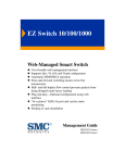
1
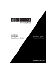
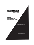
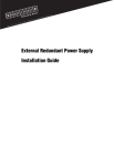
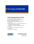
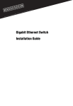
Redundant Power Unit
Fault-tolerant networking!
•
•
•
•
•
•
•
Supports up to four switch units
AC line draws power from different supply circuit
DC line provides backup power to attached devices
Thermal overload protection
Over-voltage protection for each output channel
Over-current protection can shut down the RPU
Short-circuit protection against output channels
User Guide
SMCRPU14
Redundant Power Unit
User Guide
Powers up to four SMC networking devices
38 Tesla
Irvine, CA 92618
Phone: (949) 679-8000
Janurary 2005
Pub. # 150200050500A R01
Information furnished by SMC Networks, Inc. (SMC) is believed to be accurate and reliable. However, no
responsibility is assumed by SMC for its use, nor for any infringements of patents or other rights of third
parties which may result from its use. No license is granted by implication or otherwise under any patent or
patent rights of SMC. SMC reserves the right to change specifications at any time without notice.
Copyright © 2005 by
SMC Networks, Inc.
38 Tesla
Irvine, CA 92618
All rights reserved. Printed in Taiwan
Trademarks:
SMC is a registered trademark of SMC Networks, Inc. Other product and company names are trademarks
or registered trademarks of their respective holders.
LIMITED WARRANTY
Limited Warranty Statement: SMC Networks, Inc. (“SMC”) warrants its products to be
free from defects in workmanship and materials, under normal use and service, for the
applicable warranty term. All SMC products carry a standard 90-day limited warranty from
the date of purchase from SMC or its Authorized Reseller. SMC may, at its own discretion,
repair or replace any product not operating as warranted with a similar or functionally
equivalent product, during the applicable warranty term. SMC will endeavor to repair or
replace any product returned under warranty within 30 days of receipt of the product.
The standard limited warranty can be upgraded to a Limited Lifetime* warranty by registering
new products within 30 days of purchase from SMC or its Authorized Reseller. Registration
can be accomplished via the enclosed product registration card or online via the SMC web
site. Failure to register will not affect the standard limited warranty. The Limited Lifetime
warranty covers a product during the Life of that Product, which is defined as the period of
time during which the product is an “Active” SMC product. A product is considered to be
“Active” while it is listed on the current SMC price list. As new technologies emerge, older
technologies become obsolete and SMC will, at its discretion, replace an older product in its
product line with one that incorporates these newer technologies. At that point, the obsolete
product is discontinued and is no longer an “Active” SMC product. A list of discontinued
products with their respective dates of discontinuance can be found at http://www.smc.com/
smc/pages_html/support.html.
All products that are replaced become the property of SMC. Replacement products may be
either new or reconditioned. Any replaced or repaired product carries either a 30-day limited
warranty or the remainder of the initial warranty, whichever is longer. SMC is not responsible
for any custom software or firmware, configuration information, or memory data of
Customer contained in, stored on, or integrated with any products returned to SMC pursuant
to any warranty. Products returned to SMC should have any customer-installed accessory or
add-on components, such as expansion modules, removed prior to returning the product for
replacement. SMC is not responsible for these items if they are returned with the product.
Customers must contact SMC for a Return Material Authorization number prior to returning
any product to SMC. Proof of purchase may be required. Any product returned to SMC
without a valid Return Material Authorization (RMA) number clearly marked on the outside
of the package will be returned to customers at customer’s expense. For warranty claims
within North America, please call our toll-free customer support number at (800) 762-4968.
Customers are responsible for all shipping charges from their facility to SMC. SMC is
responsible for return shipping charges from SMC to customer.
i
LIMITED WARRANTY
WARRANTIES EXCLUSIVE: IF AN SMC PRODUCT DOES NOT OPERATE AS
WARRANTED ABOVE, CUSTOMER’S SOLE REMEDY SHALL BE REPAIR OR
REPLACEMENT OF THE PRODUCT IN QUESTION, AT SMC’S OPTION. THE
FOREGOING WARRANTIES AND REMEDIES ARE EXCLUSIVE AND ARE IN
LIEU OF ALL OTHER WARRANTIES OR CONDITIONS, EXPRESS OR IMPLIED,
EITHER IN FACT OR BY OPERATION OF LAW, STATUTORY OR OTHERWISE,
INCLUDING WARRANTIES OR CONDITIONS OF MERCHANTABILITY AND
FITNESS FOR A PARTICULAR PURPOSE. SMC NEITHER ASSUMES NOR
AUTHORIZES ANY OTHER PERSON TO ASSUME FOR IT ANY OTHER
LIABILITY IN CONNECTION WITH THE SALE, INSTALLATION,
MAINTENANCE OR USE OF ITS PRODUCTS. SMC SHALL NOT BE LIABLE
UNDER THIS WARRANTY IF ITS TESTING AND EXAMINATION DISCLOSE THE
ALLEGED DEFECT IN THE PRODUCT DOES NOT EXIST OR WAS CAUSED BY
CUSTOMER’S OR ANY THIRD PERSON’S MISUSE, NEGLECT, IMPROPER
INSTALLATION OR TESTING, UNAUTHORIZED ATTEMPTS TO REPAIR, OR
ANY OTHER CAUSE BEYOND THE RANGE OF THE INTENDED USE, OR BY
ACCIDENT, FIRE, LIGHTNING, OR OTHER HAZARD.
LIMITATION OF LIABILITY: IN NO EVENT, WHETHER BASED IN CONTRACT
OR TORT (INCLUDING NEGLIGENCE), SHALL SMC BE LIABLE FOR
INCIDENTAL, CONSEQUENTIAL, INDIRECT, SPECIAL, OR PUNITIVE
DAMAGES OF ANY KIND, OR FOR LOSS OF REVENUE, LOSS OF BUSINESS, OR
OTHER FINANCIAL LOSS ARISING OUT OF OR IN CONNECTION WITH THE
SALE, INSTALLATION, MAINTENANCE, USE, PERFORMANCE, FAILURE, OR
INTERRUPTION OF ITS PRODUCTS, EVEN IF SMC OR ITS AUTHORIZED
RESELLER HAS BEEN ADVISED OF THE POSSIBILITY OF SUCH DAMAGES.
SOME STATES DO NOT ALLOW THE EXCLUSION OF IMPLIED WARRANTIES
OR THE LIMITATION OF INCIDENTAL OR CONSEQUENTIAL DAMAGES FOR
CONSUMER PRODUCTS, SO THE ABOVE LIMITATIONS AND EXCLUSIONS
MAY NOT APPLY TO YOU. THIS WARRANTY GIVES YOU SPECIFIC LEGAL
RIGHTS, WHICH MAY VARY FROM STATE TO STATE. NOTHING IN THIS
WARRANTY SHALL BE TAKEN TO AFFECT YOUR STATUTORY RIGHTS.
* SMC will provide warranty service for one year following discontinuance from the active
SMC price list. Under the limited lifetime warranty, internal and external power supplies, fans,
and cables are covered by a standard one-year warranty from date of purchase.
SMC Networks, Inc.
38 Tesla
Irvine, CA 92618
ii
COMPLIANCES
COMPLIANCES
FCC - Class B
This equipment has been tested and found to comply with the limits for a Class B digital device,
pursuant to Part 15 of the FCC Rules. These limits are designed to provide reasonable protection
against harmful interference in a residential installation. This equipment generates, uses and can
radiate radio frequency energy and, if not installed and used in accordance with instructions, may
cause harmful interference to radio communications. However, there is no guarantee that the interference will not occur in a particular installation. If this equipment does cause harmful interference
to radio or television reception, which can be determined by turning the equipment off and on, the
user is encouraged to try to correct the interference by one or more of the following measures:
• Reorient the receiving antenna
• Increase the separation between the equipment and receiver
• Connect the equipment into an outlet on a circuit different from that to which the receiver is
connected
• Consult the dealer or an experienced radio/TV technician for help
Industry Canada - Class B
This digital apparatus does not exceed the Class B limits for radio noise emissions from digital
apparatus as set out in the interference-causing equipment standard entitled
“Digital Apparatus,” ICES-003 of the Department of Communications.
Cet appareil numérique respecte les limites de bruits radioélectriques applicables aux appareils
numériques de Classe B prescrites dans la norme sur le matériel brouilleur: “Appareils
Numériques,” NMB-003 édictée par le ministère des Communications.
Japan VCCI Class B
iii
COMPLIANCES
EC Conformance Declaration - Class B
SMC contact for these products in Europe is:
SMC Networks Europe,
Edificio Conata II,
Calle Fructuós Gelabert 6-8, 2o, 4a,
08970 - Sant Joan Despí, Barcelona, Spain.
This information technology equipment complies with the requirements of the Council Directive
89/336/EEC on the Approximation of the laws of the Member States relating to Electromagnetic
Compatibility and 73/23/EEC for electrical equipment used within certain voltage limits and the
Amendment Directive 93/68/EEC. For the evaluation of the compliance with these Directives,
the following standards were applied:
RFI Emission:
• Limit class B according to EN 55022:1998
• Limit class A for harmonic current emission according to
EN 61000-3-2/1995
• Limitation of voltage fluctuation and flicker in low-voltage supply
system according to EN 61000-3-3/1995
Immunity:
• Product family standard according to EN 55024:1998
• Electrostatic Discharge according to EN 61000-4-2:1995
(Contact Discharge: ±4 kV, Air Discharge: ±8 kV)
• Radio-frequency electromagnetic field according to EN 61000-4-3:1996
(80 - 1000 MHz with 1 kHz AM 80% Modulation: 3 V/m)
• Electrical fast transient/burst according to EN 61000-4-4:1995 (AC/
DC power supply: ±1 kV, Data/Signal lines: ±0.5 kV)
• Surge immunity test according to EN 61000-4-5:1995
(AC/DC Line to Line: ±1 kV, AC/DC Line to Earth: ±2 kV)
• Immunity to conducted disturbances, Induced by radio-frequency
fields: EN 61000-4-6:1996 (0.15 - 80 MHz with
1 kHz AM 80% Modulation: 3 V/m)
• Power frequency magnetic field immunity test according to
EN 61000-4-8:1993 (1 A/m at frequency 50 Hz)
• Voltage dips, short interruptions and voltage variations immunity test
according to EN 61000-4-11:1994 (>95% Reduction @10 ms, 30%
Reduction @500 ms, >95% Reduction @5000 ms)
LVD:
iv
• EN 60950 :2000
COMPLIANCES
Australia AS/NZS 3548 (1995) - Class B
SMC contact for products in Australia is:
SMC Communications Pty. Ltd.
Suite 18, 12 Tryon Road,
Lindfield NSW2070,
Phone: 61-2-94160437
Fax: 61-2-94160474
Please read the following safety information carefully
before installing the RPU:
WARNING: Installation and removal of the unit must be carried out by
qualified personnel only.
• This guide is intended for use by network administrators who are
responsible for setting up and installing network equipment;
consequently it assumes a basic working knowledge of LANs (Local
Area Networks).
• The unit must be connected to an earthed (grounded) outlet to comply
with international safety standards.
• Do not connect the unit to an A.C. outlet (power supply) without an
earth (ground) connection.
• The appliance coupler (the connector to the unit and not the wall plug)
must have a configuration for mating with an EN 60320/IEC 320
appliance inlet.
• The socket outlet must be near to the unit and easily accessible. You
can only remove power from the unit by disconnecting the power cord
from the outlet.
• This unit operates under SELV (Safety Extra Low Voltage) conditions
according to IEC 60950. The conditions are only maintained if the
equipment to which it is connected also operates under SELV
conditions.
v
COMPLIANCES
France and Peru only
This unit cannot be powered from IT† supplies. If your supplies are of IT type, this unit must
be powered by 230 V (2P+T) via an isolation transformer ratio 1:1, with the secondary connection point labelled Neutral, connected directly to earth (ground).
†
Impédance à la terre
Power Cord Set
U.S.A. and Canada
The cord set must be UL-approved and CSA certified.
The minimum specifications for the flexible cord are:
- No. 18 AWG - not longer than 2 meters, or 16 AWG.
- Type SV or SJ
- 3-conductor
The cord set must have a rated current capacity of at least 10 A.
The attachment plug must be an earth-grounding type with NEMA 5-15P
(15 A, 125 V) or NEMA 6-15P (15 A, 250 V) configuration.
Denmark
The supply plug must comply with Section 107-2-D1, Standard DK2-1a
or DK2-5a.
Switzerland
The supply plug must comply with SEV/ASE 1011.
U.K.
The supply plug must comply with BS1363 (3-pin 13 A) and be fitted with
a 5 A fuse which complies with BS1362.
The mains cord must be <HAR> or <BASEC> marked and be of type
HO3VVF3GO.75 (minimum).
Europe
The supply plug must comply with CEE7/7 (“SCHUKO”).
The mains cord must be <HAR> or <BASEC> marked and be of type
HO3VVF3GO.75 (minimum).
IEC-320 receptacle.
Veuillez lire à fond l'information de la sécurité suivante
avant d'installer le RPU:
AVERTISSEMENT: L’installation et la dépose de ce groupe doivent être
confiés à un personnel qualifié.
• Ne branchez pas votre appareil sur une prise secteur (alimentation
électrique) lorsqu'il n'y a pas de connexion de mise à la terre (mise à la
masse).
vi
COMPLIANCES
• Vous devez raccorder ce groupe à une sortie mise à la terre (mise à la
masse) afin de respecter les normes internationales de sécurité.
• Le coupleur d’appareil (le connecteur du groupe et non pas la prise
murale) doit respecter une configuration qui permet un branchement
sur une entrée d’appareil EN 60320/IEC 320.
• La prise secteur doit se trouver à proximité de l’appareil et son accès
doit être facile. Vous ne pouvez mettre l’appareil hors circuit qu’en
débranchant son cordon électrique au niveau de cette prise.
• L’appareil fonctionne à une tension extrêmement basse de sécurité qui
est conforme à la norme IEC 60950. Ces conditions ne sont
maintenues que si l’équipement auquel il est raccordé fonctionne dans
les mêmes conditions.
France et Pérou uniquement:
Ce groupe ne peut pas être alimenté par un dispositif à impédance à la terre. Si vos alimentations sont du type impédance à la terre, ce groupe doit être alimenté par une tension de 230 V
(2 P+T) par le biais d’un transformateur d’isolement à rapport 1:1, avec un point secondaire
de connexion portant l’appellation Neutre et avec raccordement direct à la terre (masse).
Cordon électrique - Il doit être agréé dans le pays d’utilisation
Etats-Unis et Canada:
Le cordon doit avoir reçu l’homologation des UL et un certificat de la
CSA.
Les spe'cifications minimales pour un cable flexible sont AWG No. 18,
ouAWG No. 16 pour un cable de longueur infe'rieure a` 2 me'tres.
- type SV ou SJ
- 3 conducteurs
Le cordon doit être en mesure d’acheminer un courant nominal d’au
moins 10 A.
La prise femelle de branchement doit être du type à mise à la terre (mise
à la masse) et respecter la configuration NEMA 5-15P (15 A, 125 V) ou
NEMA 6-15P (15 A, 250 V).
Danemark:
La prise mâle d’alimentation doit respecter la section 107-2 D1 de la
norme DK2 1a ou DK2 5a.
Suisse:
La prise mâle d’alimentation doit respecter la norme SEV/ASE 1011.
Europe
La prise secteur doit être conforme aux normes CEE 7/7 (“SCHUKO”)
LE cordon secteur doit porter la mention <HAR> ou <BASEC> et doit
être de type HO3VVF3GO.75 (minimum).
vii
COMPLIANCES
Bitte unbedingt vor dem Einbauen des RPU die
folgenden Sicherheitsanweisungen durchlesen:
WARNUNG: Die Installation und der Ausbau des Geräts darf nur durch
Fachpersonal erfolgen.
• Diese Anleitung ist fr die Benutzung durch Netzwerkadministratoren
vorgesehen, die fr die Installation und das einstellen von
Netzwerkkomponenten verantwortlich sind; sie setzt Erfahrung bei
der Arbeit mit LANs (Local Area Networks) voraus.
• Das Gerät sollte nicht an eine ungeerdete Wechselstromsteckdose
angeschlossen werden.
• Das Gerät muß an eine geerdete Steckdose angeschlossen werden,
welche die internationalen Sicherheitsnormen erfüllt.
• Der Gerätestecker (der Anschluß an das Gerät, nicht der
Wandsteckdosenstecker) muß einen gemäß EN 60320/IEC 320
konfigurierten Geräteeingang haben.
• Die Netzsteckdose muß in der Nähe des Geräts und leicht zugänglich
sein. Die Stromversorgung des Geräts kann nur durch Herausziehen
des Gerätenetzkabels aus der Netzsteckdose unterbrochen werden.
• Der Betrieb dieses Geräts erfolgt unter den SELV-Bedingungen
(Sicherheitskleinstspannung) gemäß IEC 60950. Diese Bedingungen
sind nur gegeben, wenn auch die an das Gerät angeschlossenen Geräte
unter SELV-Bedingungen betrieben werden
Stromkabel. Dies muss von dem Land, in dem es benutzt wird geprüft werden:
Schweiz
Dieser Stromstecker muß die SEV/ASE 1011Bestimmungen einhalten.
Europe
Das Netzkabel muß vom Typ HO3VVF3GO.75 (Mindestanforderung)
sein und die Aufschrift <HAR> oder <BASEC> tragen.
Der Netzstecker muß die Norm CEE 7/7 erfüllen (”SCHUKO”).
viii
COMPLIANCES
Warnings and Cautionary Messages
Warning:
This product does not contain any serviceable user parts.
Warning:
Installation and removal of the unit must be carried out by qualified personnel
only.
Warning:
When connecting this device to a power outlet, connect the field ground lead
on the tri-pole power plug to a valid earth ground line to prevent electrical
hazards.
Warning:
This switch uses lasers to transmit signals over fiber optic cable. The lasers are
compliant with the requirements of a Class 1 Laser Product and are inherently
eye safe in normal operation. However, you should never look directly at a
transmit port when it is powered on.
Caution:
Wear an anti-static wrist strap or take other suitable measures to prevent
electrostatic discharge when handling this equipment.
Caution:
Do not plug a phone jack connector in the RJ-45 port. This may damage this
device. Les raccordeurs ne sont pas utilisé pour le système téléphonique!
Caution:
Use only twisted-pair cables with RJ-45 connectors that conform to FCC
standards.
Warnings (in German)
Achtung:
Dieses Produkt enthält keine Teile, die eine Wartung vom Benutzer benötigen.
Achtung:
Installation und Deinstallation des Gerätes müssen von qualifiziertem
Servicepersonal durchgeführt werden.
Achtung:
Wenn das Gerät an eine Steckdose angeschlossen wird, muß der Masseanschluß
am dreipoligen Netzstecker mit Schutzerde verbunden werden, um elektrische
Gefahren zu vermeiden.
Achtung:
Dieses Gerät nutzt Laser zur Signalübertragung über Glasfasern. Die Laser
entsprechen den Anforderungen an eine Lasereinrichtung der Klasse 1 und sind
durch ihre Bauart im normalen Betrieb sicher für die Augen. Trotzdem sollte
niemals direkt in den einen Übertragungskanal geblickt werden, wenn er
eingeschaltet ist.
ix
Environmental Statement
The manufacturer of this product endeavours to sustain an environmentally-friendly policy
throughout the entire production process. This is achieved though the following means:
•
•
•
•
•
•
Adherence to national legislation and regulations on environmental production standards.
Conservation of operational resources.
Waste reduction and safe disposal of all harmful un-recyclable by-products.
Recycling of all reusable waste content.
Design of products to maximize recyclables at the end of the product’s life span.
Continual monitoring of safety standards.
End of Product Life Span
This product is manufactured in such a way as to allow for the recovery and disposal of all included
electrical components once the product has reached the end of its life.
Manufacturing Materials
There are no hazardous nor ozone-depleting materials in this product.
Documentation
All printed documentation for this product uses biodegradable paper that originates from
sustained and managed forests. The inks used in the printing process are non-toxic.
Purpose
This guide details the hardware features of the switch, including Its physical and
performance-related characteristics, and how to install the switch.
Audience
The guide is intended for use by network administrators who are responsible for installing and
setting up network equipment; consequently, it assumes a basic working knowledge of LANs
(Local Area Networks).
Diese Anleitung ist für die Benutzung durch Netzwerkadministratoren vorgesehen, die für die
Installation und das einstellen von Netzwerkkomponenten verantwortlich sind; sie setzt
Erfahrung bei der Arbeit mit LANs (Local Area Networks) voraus.
x
TABLE OF CONTENTS
1
About the Redundant Power Unit . . . . . . . . . . . . . . . .1-1
Overview . . . . . . . . . . . . . . . . . . . . . . . . . . . . . . . . . . . . . . . . . . . . . . . . . .
Features and Benefits . . . . . . . . . . . . . . . . . . . . . . . . . . . . . . . . . . . . . . . .
Front and Rear Panels . . . . . . . . . . . . . . . . . . . . . . . . . . . . . . . . . . . . . . .
LEDs . . . . . . . . . . . . . . . . . . . . . . . . . . . . . . . . . . . . . . . . . . . . . . . . . . . . .
2
Installing the Redundant Power Unit . . . . . . . . . . . . . 2-1
Installation . . . . . . . . . . . . . . . . . . . . . . . . . . . . . . . . . . . . . . . . . . . . . . . .
Selecting a Site . . . . . . . . . . . . . . . . . . . . . . . . . . . . . . . . . . . . . . . . . . . . .
Equipment Checklist . . . . . . . . . . . . . . . . . . . . . . . . . . . . . . . . . . . . . . . .
Package Contents . . . . . . . . . . . . . . . . . . . . . . . . . . . . . . . . . . . . .
Optional Rack-Mounting Equipment . . . . . . . . . . . . . . . . . . . . .
Mounting . . . . . . . . . . . . . . . . . . . . . . . . . . . . . . . . . . . . . . . . . . . . . . . . .
Rack Mounting . . . . . . . . . . . . . . . . . . . . . . . . . . . . . . . . . . . . . . .
Desktop or Shelf Mounting . . . . . . . . . . . . . . . . . . . . . . . . . . . . .
Connecting Switches to the RPU . . . . . . . . . . . . . . . . . . . . . . . . . . . . . .
A
1-1
1-1
1-2
1-2
2-1
2-1
2-2
2-2
2-2
2-3
2-3
2-6
2-6
Troubleshooting . . . . . . . . . . . . . . . . . . . . . . . . . . . . . A-1
Diagnosing RPU Indicators . . . . . . . . . . . . . . . . . . . . . . . . . . . . . . . . . . . A-1
Power and Cooling Problems . . . . . . . . . . . . . . . . . . . . . . . . . . . . . . . . . A-2
Installation . . . . . . . . . . . . . . . . . . . . . . . . . . . . . . . . . . . . . . . . . . . . . . . . A-2
B
Specifications . . . . . . . . . . . . . . . . . . . . . . . . . . . . . . . . B-1
Physical Characteristics . . . . . . . . . . . . . . . . . . . . . . . . . . . . . . . . . . . . . . B-1
Compliances . . . . . . . . . . . . . . . . . . . . . . . . . . . . . . . . . . . . . . . . . . . . . . . B-2
ix
TABLE OF CONTENTS
x
CHAPTER 1:
ABOUT THE REDUNDANT
POWER UNIT
Overview
This Redundant Power Unit (SMCRPU14) can supply 600 Watts of backup
power to four switches in the event of an AC loss or failure of an internal
power supply.
Features and Benefits
•
Supports four switch units with 12 VDC supply of up to 150 W.
•
Indicator LEDs located on the front panel.
•
RPU AC line cord can draw power from a different supply circuit.
•
DC line cords provide backup power to attached devices.
•
Thermal overload protection prevents the RPU from overheating if a
thermal overload occurs.
•
Over-voltage protection shuts down an output channel if the voltage
exceeds a preset threshold.
•
Over-current protection shuts down the RPU if the output load
exceeds a preset threshold.
1-1
•
Short-circuit protection prevents the RPU from being damaged from
a short circuit on any output channel.
•
The RPU will operate under a no-load condition.
Front and Rear Panels
Four status indicators Link, Activity, Fan, Thermal, and Power indicators
are located on the RPU’s front panel. While the AC supply and DC backup
receptacles are located on the RPU’s rear panel.
Figure 1-1 Front and Rear Panels
Link
Activity
Fan Thermal Power
100-240V, 50-60Hz 10A
LEDs
The following diagram and tables describe the functions of the LEDs.
Figure 1-2 LEDs
Link
Activity
Fan Thermal Power
1-2
Table 1-1 Port Status LEDs
LED (1-4)
Condition
Status
Link
Off
The port does not have a valid connection to a
switch.
On Yellow
The port has a valid connection to a switch.
Flashing
Yellow
There has been an RPU internal power failure.
Off
The port is not providing power to the
connected switch.
Flashing
Green
The port has been shut down due to one of the
following conditions:
Activity
The unit has detected an over-current
condition.
One or more of the unit’s fans have failed.
On Green
The port is providing power to a connected
switch.
Table 1-2 System LEDs
LED
Condition
Status
Fan
On Green
The fans are functioning normally.
Flashing
Yellow
One or more fans are not operating properly.
Off
The unit is powered off.
On Green
The temperature of the unit is within an
acceptable range.
Flashing
Yellow
Indicates a high temperature that is approaching
an over-temperature condition.
Off
The thermal unit has failed, or the unit is
powered off.
On Green
AC power is being supplied to the RPU.
Off
No AC power is being supplied to the RPU.
Thermal
Power
1-3
1-4
CHAPTER 2:
INSTALLING THE
REDUNDANT POWER UNIT
Installation
The RPU may be placed on a desktop or mounted in a rack.
Caution:
DO NOT place the RPU on the floor as the case is not
waterproof. It is recommended that this RPU be installed in
a network equipment rack.
Selecting a Site
RPU units can be mounted in a standard 19-inch equipment rack or on a
flat surface. Be sure to follow the guidelines below when choosing a
location.
•
The site should:
-
be at the center of all the devices you want to link and near a
power outlet.
-
be able to maintain its temperature within 0 to 45 °C (32 to
110 °F) and its humidity within 5% to 95%, non-condensing
-
provide adequate space (approximately two inches) on all sides for
proper air flow
-
be accessible for installing, cabling and maintaining the devices
-
allow the status LEDs to be clearly visible
2-1
-
Make sure that a separate grounded power outlet that provides
100 to 240 VAC, 50-60 Hz, is within 2 m (6.56 feet) of each device
and is powered from an independent circuit breaker. As with any
equipment, using a filter or surge suppressor is recommended.
Equipment Checklist
After unpacking the RPU, check the contents to be sure you have received
all the components. Then, before beginning the installation, be sure you
have all other necessary installation equipment.
Package Contents
•
Redundant Power Unit (SMCRPU14)
•
One AC Supply Power Cord — US, Continental Europe or UK
•
Four DC Backup Power Cords with IEC connectors on both ends
(length 152 cm/59.84 inches each)
•
Rack Mounting Kit containing brackets and screws
•
Adhesive feet
•
Registration Card
Optional Rack-Mounting Equipment
If you plan to rack-mount the RPU, be sure to have the following
equipment available:
2-2
•
Four mounting screws for each device you plan to install in a
rack—these are not included
•
A screwdriver (Phillips or flathead, depending on the type of screws
used)
Mounting
RPU units can be mounted in a standard 19-inch equipment rack or on a
desktop or shelf. Mounting instructions for each type of site follow.
Rack Mounting
Before rack mounting the unit, pay particular attention to the following
factors:
•
Temperature: Since the temperature within a rack assembly may be
higher than the ambient room temperature, check that the
rack-environment temperature is within the specified operating
temperature range.
•
Mechanical Loading: Do not place any equipment on top of a
rack-mounted unit.
•
Circuit Overloading: Be sure that the supply circuit to the rack
assembly is not overloaded.
•
Grounding: Rack-mounted equipment should be properly grounded.
Particular attention should be given to supply connections other than
direct connections to the mains.
2-3
To rack-mount devices:
1. Attach the brackets to the device using the screws provided in the
Bracket Mounting Kit.
Figure 2-1 Attaching the Brackets
Li nk
Ac tiv
ity
Fa n
Th er
m al
Po we
r
2. Mount the device in the rack, using four rack-mounting screws (not
provided).
Figure 2-2 Installing the RPU in a Rack
Li nk
Ac tiv
ity
Fa n
Th er
m al
Po w er
3. If also installing RPUs, mount them in the rack below the other
devices.
2-4
Montage (Rack Mounting - German)
SMCRPU14 RPU-Einheiten können an ein standardmäßiges 19-Zoll Einrichtungsrack, einen
Arbeitstisch oder ein Regal montiert werden. Folgend finden Sie die Montageanweisungen für
jeden Positionstyp.
Rack-Montage
Beachten Sie die folgenden Faktoren, bevor Sie die Rack-Montage beginnen:
•
•
•
•
Temperatur: Da die Temperatur innerhalb einer Rackeinheit höher als die
Raumumgebungstemperatur sein kann, stellen Sie bitte sicher, dass die Rackumgebungstemperatur
innerhalb des angegebenen Betriebstemperaturbereichs liegt. (Siehe "Temperatur" auf Seite C-1.)
Mechanische Last: Stellen Sie kein Gerät auf eine Rack-Montageeinheit.
Stromüberlastung: Stellen Sie sicher, dass der Netzkreis der Rackeinheit nicht überlastet wird.
Erdung: Die Rack-Montageeinheit muss richtig geerdet werden. Besondere Acht sollten Sie bei
Verbindungen geben, die nicht direkt zum Netz führen.
So montieren Sie Geräte an ein Rack:
1. Befestigen Sie die Metallwinkel mit den im Metallwinkel-Montageset erhältlichen Schrauben an dem
Gerät.
2. Befestigen Sie das Gerät mit vier Rackmontageschrauben (nicht beigelegt) an dem Rack.
3. Wenn Sie nur einen Switch installieren, dann springen Sie bitte über zu "Verbinden mit einer
Stromquelle" auf Seite -6 am Ende dieses Kapitels.
Wenn Sie mehrere Switches installieren möchten, dann montieren Sie sie untereinander in
einer beliebigen Reihenfolge.
2-5
Desktop or Shelf Mounting
1. Attach the four adhesive feet to the bottom of the first RPU unit.
Figure 2-3 Attaching the Adhesive Feet
10 0-2
40 V,
50 -60
Hz
10 A
2. Set the device on a flat surface near an AC power source, making sure
there are at least five centimeters or two inches of space on all sides for
proper air flow.
Connecting Switches to the RPU
Caution:
DO NOT connect the RPU to an AC power source until
DC power cords have been connected to the supported
switches.
To connect switches to the RPU:
1. Connect one end of an AC cord to the AC receptacle on each
supported switch, and the other end to a grounded power outlet.
2-6
Figure 2-4 Power Receptacle
100-240V, 50-60Hz 10A
2. Connect one end of a DC cord to the redundant power receptacle on
the supported switch and the other end to an available receptacle on
the RPU.
3. Repeat steps 1 and 2 for connecting up to four supported switches to
the RPU.
4. Connect one end of the AC cord to the AC receptacle on the RPU,
and the other end to a grounded power outlet.
5. Check the LEDs on the RPU to ensure proper operation. The Link
LEDs for connected switches should light up. If the LEDs indicate
otherwise, see “Troubleshooting” on page A-1 for more information.
2-7
Figure 2-5 Connecting the RPU in a Stack
Stack
RPU input port
100-240V, 50-60Hz 8A
RPU Unit
RPU output port
AC Power
Supply No.1
AC Power
Supply No.2
Note: For International use, you may need to change the AC line cord. You
must use a line cord set that has been approved for the receptacle type
in your country.
2-8
APPENDIX A
TROUBLESHOOTING
Diagnosing RPU Indicators
Table A-1 Troubleshooting Chart
Symptom
Action
Power LED is Off
• Internal power supply is disconnected.
• Check connections between the RPU, the power cord,
and the wall outlet.
• Contact Technical Support.
Link LED is Off
• The port does not have a valid connection to a switch.
• Check connections between the RPU and the switch.
• Check that power is being supplied to the RPU.
Link LED is Flashing
Yellow
• There has been an RPU internal power failure.
• Contact Technical Support.
Activity LED is
Flashing Green
• The port has been shut down due to one of the following
conditions:
- The unit has detected an over-current condition.
- One or more of the unit’s fans have failed.
• Check if the Fan LED is off, which indicates a fan failure.
• Check that the attached switch does not require more than
150 W of power.
• Power cycle the RPU to clear the condition.
• If the condition persists, contact Technical Support.
Fan LED is Flashing
Yellow
• One or more fans are not operating properly.
• Replace the unit as soon as possible.
A-1
Table A-1 Troubleshooting Chart
Symptom
Action
Fan LED is Off
• The unit is powered off.
Thermal LED is
Flashing Yellow
• Indicates a high temperature that is approaching an
over-temperature condition.
• Check that the unit's cooling fans are operating normally.
• Power off the RPU unit and allow to cool.
• If the condition persists, contact Technical Support.
Power and Cooling Problems
If the PWR LED does not turn on when the power cord is plugged in, you
may have a problem with the power outlet, power cord, or internal power
supply. However, if the unit powers off after running for a while, check for
loose power connections, power losses or surges at the power outlet, and
verify that the fans on the unit are unobstructed and running prior to
shutdown. If you still cannot isolate the problem, then the internal power
supply may be defective. In this case, contact your distributor for
assistance.
Installation
Verify that all system components have been properly installed. If one or
more components appear to be malfunctioning (such as the power cord or
RPU cable), test them in an alternate environment where you are sure that
all the other components are functioning properly.
A-2
APPENDIX B.
SPECIFICATIONS
Physical Characteristics
Ports
4 RPU DC power outlets (IEC socket 216C743-07)
LEDs
Port: Link, Activity
System: Power, Fan, Thermal
Weight
5.5 kg (12.1 lbs)
Size
44.0 x 32.3 x 4.3 cm (17.34 x 12.6 x 1.69 in.)
Temperature
Operating: 0 to 45 °C (32 to 110°F)
Storage: -40 to 70 °C (-40 to 158 °F)
Humidity
Operating: 20% to 90%
AC Input
100 to 240 V, 50 to 60 Hz
EIA Ratings
10 A @ 125 VAC
10 A @ 250 VAC
DC Power Cable Connector
14-pin P-Type connector
B-1
Power Supply
Internal, auto-ranging transformer: 100 to 240 VAC, 50 to 60 Hz
Output 11.5 VDC
Power Consumption
644 W (Maximum)
161 W (Maximum per port)
Maximum Current
7.8 A @ 110 VAC
3.5 A @ 240 VAC
Overload Protection
Ports are shutdown when output exceeds 150 W
Power Supply
+12 VDC
Initial accuracy: +/- 1%
Current: 2 A (minimum), 10 A (maximum)
Line regulation: +/- 1%
Load regulation: +/- 10%
Overshoot and undershoot: 5%
Compliances
CE Mark
Emissions
FCC Class B
Industry Canada Class B
CISPR Class B
VCCI Class B
AS/NZS 3548 (1995) Class B
Immunity
EN 55024
B-2
Safety
CSA/ C US (CSA 60950-00 & UL60950)
CB: IEC 60950
EN 60950 (TÜV/GS)
B-3
B-4
INDEX
A
I
adhesive feet, attaching 2-6
air flow requirements 2-1
brackets, attaching 2-4
installation
desktop or shelf mounting 2-6
power requirements 2-2
problems A-2
rack mounting 2-3
site requirements 2-1
C
L
CE Mark 0-iv
compliances 0-iii
EMC B-2
safety B-3
contents of package 2-2
cooling problems A-2
cord sets, international 2-8
LED indicators
problems A-1
location requirements 2-1
B
D
M
mounting the RPU
in a rack 2-3
on a desktop or shelf 2-6
desktop mounting 2-6
P
E
package contents 2-2
power, connecting to 2-7
problems, troubleshooting A-1
EC conformance 0-iv
EMC/safety compliance 0-iii
equipment checklist 2-2
F
front panel of RPU 1-2
G
grounding for racks 2-3
R
rack mounting 2-3
rear panel of RPU 1-2
RPU
installing in a rack 2-4
rubber foot pads, attaching 2-6
S
screws for rack mounting 2-2
site selelction 2-1
INDEX-1
INDEX
specifications
compliances B-2
environmental B-1
physical B-1
power B-2
standards
compliance B-2
IEEE B-2
standards compliance 0-iii
surge suppressor, using 2-2
T
temperature within a rack 2-3
troubleshooting
in-band access A-2
power and cooling problems A-2
RPU indicators A-1
INDEX-2
FOR TECHNICAL SUPPORT, CALL:
From U.S.A. and Canada (24 hours a day, 7 days a week)
(800) SMC-4-YOU; (949) 679-8000; Fax: (949) 679-1481
From Europe (8:00 AM - 5:30 PM UK Time)
44 (0) 118 974 8700; Fax: 44 (0) 118 974 8701
INTERNET
E-mail addresses:
[email protected]
[email protected]
Driver updates:
http://www.smc.com/index.cfm?action=tech support drivers downloads
World Wide Web:
http://www.smc.com/
http://www.smc-europe.com/
FOR LITERATURE OR ADVERTISING RESPONSE, CALL:
U.S.A. and Canada:
Spain:
UK:
France:
Italy:
Benelux:
Central Europe:
Switzerland:
Nordic:
Northern Europe:
Eastern Europe:
Sub Saharian Africa:
North Africa:
Russia:
PRC:
Taiwan:
Asia Pacific:
Korea:
Japan:
Australia:
India:
(800) SMC-4-YOU;
34-93-477-4935;
44 (0) 118 974 8700;
33 (0) 41 38 32 32;
39 02 739 12 33;
31 33 455 72 88;
49 (0) 89 92861-0;
41 (0) 1 9409971;
46 (0) 868 70700;
44 (0) 118 974 8700;
34 -93-477-4920;
27-11 314 1133;
34 93 477 4920;
7 (095) 290 29 96;
86-10-6235-4958;
886-2-2659-9669;
(65) 238 6556;
82-2-553-0860;
81-45-224-2332;
61-2-9416-0437;
91-22-8204437;
Fax (949) 679-1481
Fax 34-93-477-3774
Fax 44 (0) 118 974 8701
Fax 33 (0) 41 38 01 58
Fax 39 02 739 14 17
Fax 31 33 455 73 30
Fax 49 (0) 89 92861-230
Fax 41 (0) 1 9409972
Fax 46 (0) 887 62 62
Fax 44 (0) 118 974 8701
Fax 34 93 477 3774
Fax 27-11 314 9133
Fax 34 93 477 3774
Fax 7 (095) 290 29 96
Fax 86-10-6235-4962
Fax 886-2-2659-9666
Fax (65) 238 6466
Fax 82-2-553-7202
Fax 81-45-224-2331
Fax 61-2-9416-0474
Fax 91-22-8204443
If you are looking for further contact information, please visit www.smc.com or
www.smc-europe.com.
38 Tesla
Irvine, CA 92618
Phone: (949) 679-8000
Model Numbers: SMCRPU14
Publication Number: 150200050500A E012005-R01