1
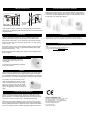
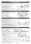
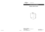
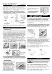
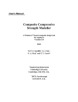
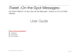
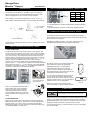
Garage Door
MonitorTM Sensor
Model GM-434T
TM
1. INTRODUCTION
2. SET UP THE GARAGE DOOR MONITOR
The garage door monitorTM sensor is designed to monitor the status of
your garage door and advise you if the door is open. By placing the
sensor on the door panel, you will be alerted when the door is open.
When the garage door is open, receiver will beep and flash.
Zone
connectors
In this package, you should find a garage door monitor sensor, 3V
lithium battery, double-sided foam tape, mounting accessories and a clip.
TM
SENSOR (CONT)
A
B
Zone 1
+
+
Zone 2
+
-
Zone 3
-
+
Zone 4
-
-
Table 1
4 pcs 3 x 18 screws
1 pc 2 x 5 screw
Clip
3V Lithium
battery
Garage Door
MonitorTM Sensor
“+” in the table means the connec tor for that position should be placed on
the posts.
“-“ in the table means the connector for that position should be removed.
TM
3. POWER UP THE GARAGE DOOR MONITOR SENSOR
After setting up all the connectors, the sensor is ready to be powered up.
Double-sided foam tape
Remove the top cover on the sensor and insert the 3V lithium battery to the
sensor as shown in the diagram.
Mounting plate
Please follow the instructions below to set up your garage door monitor
sensor properly.
TM
2. SET UP THE GARAGE DOOR MONITOR
After insert the battery to the sensor, the receiver will respond to the
transmitted signal depending on the orientation of the sensor.
SENSOR
“+” positive
side up
1. CODE CONNECTORS
In order for the sensor to communicate with the receiver properly, the
sensor’s code must match with the receiver’s code. Code connectors 1
to 6 can be found by opening the top cover of the sensor and the back
cover of the receiver. User is required to set these code connectors
randomly and the code settings on the sensor and receiver must be the
same. Each position of the code connector can be set to “+”, “-” or “0”
position. Refer to the diagram below to set the code connectors
properly. If the connector is placed on the top and middle posts, that
column is set on “ + ”. If the connector is placed on the middle and bottom
posts, that column is set on “ - ”. If the connector is removed completely,
(not placed on any posts), it is set to “ 0 ”. (see diagram for examples of
how to set a column to the three different positions).
Note: A connector can
be removed with the
clip, as shown.
You can change the orientation of the sensor and
you should see the change in response of the
receiver. If the sensor and receiver are working
properly in close proximity, you can now begin to
install the sensor onto your garage door.
NOTE: It is normal to hear a rattle from the
sensor when tilted or rotated to another position.
Code Connectors on Sensor
‘0’
Note: If you experience interference from a
nearby system, which could accidentally
trigger your system, please change the
code settings on the sensor and receiver.
The code setting on the sensor and receiver
should still match after changing the code
setting.
If the sensor is face up in the vertical position, the
green LED on the receiver will glow steadily,
indicating the sensor is in a closed position.
If the sensor is face down in the horizontal
position, one of the red LED on the receiver will
flash, and the buzzer on the receiver unit will also
emit beeping to indicate a door is open.
Clip
Open the top cover
Insert 3V lithium battery to the sensor
Vertical
Horizontal
4. INSTALLATION
‘+’
‘-’
2. ZONE CONNECTORS
Each receiver can work with up to 4 different sensors (to represent 4
different zones on the receiver). There are 2 connectors that determine
the zone number 1, 2, 3 and 4. These 2 connectors can be found by
opening the top plastic cover, near the code connectors with marking “A” &
“B”. Please follow table 1 to set the zone.
WARNING
Unplug the power cord of your garage door opener
before installation to ensure power is not connected.
Attached the sensor to the garage door with double-sided foam tape if the
surface of your garage door is smooth and clean enough to provide a
good adhesive surface, such surface can usually be found on a metal
garage door. Please ensure the surface is smooth and clean.
For wooden garage doors, it is recommended to use the mounting plate
and screws as well.
4. INSTALLATION (CONT)
9. OTHER HOUSEHOLD ALERT ® SENSORS
The Household Alert® receiver can work with up to 4 different sensors:
garage door monitor sensors, door / window sensors, water sensors,
indoor/outdoor motion sensors, etc. Please visit www.skylinkhome.com
or contact us at [email protected] for more information of how
to fully utilize your Garage Door MonitorTM.
Mounting plate
and screws
(optional)
Double-sided Sensor
foam tape
Note: Mount the sensor near the top of the garage door for best results.
Note: Ensure you straighten up the antenna on the receiver to receive the best
possible reception.
5. OPERATION
When the garage door is open, the sensor will send a signal to the
receiver. It will beep and the corresponding zone red LED will flash.
10. WARRANTY
If, within one year from date of purchase, this pro duct should become defective
(except battery), due to faulty workmanship or materials, it will be repaired or
replaced, without charge. Proof of purchase and a Return Authorization are required.
If the sensor is set to zone 1, zone 1 red LED on the receiver will flash,
and the receiver will emit a continuous “single beep”, i.e. “beep” pause,
“beep”, pause….. etc.
If the sensor is set to zone 4, zone 4 red LED will flash, and the receiver
will emit a con-tinuous “4 beeps”, i.e. “beep beep beep beep” pause “beep
beep beep beep” pause ……etc.
11. CUSTOMER SERVICE
If you would like to order Skylink’s products or have difficulty getting them to work,
please :
1. visit our FAQ website at www.skylinkhome.com , or
2. email us at [email protected]
By the number of beeps emitted by the receiver, user can identify which
zone is triggered.
6. BUZZER VOLUME
You can select the buzzer volume by
switching the volume switch to “HI” or
“LO” position.
The buzzer can be disabled by switching
to the “OFF” position.
7. MUTE
When a sensor is triggered for a long period of time, you may stop the
buzzer by pressing the mute button. When another signal comes again,
you can disable the buzzer for all currently activated sensors by pressing
the mute button. The receive will beep again if it receives another signal.
For instance, if you are working on your
lawn with the garage door open, you may
want to disable the buzzer for this garage
door only. Then you can press the “Mute”
button after it starts to sound. If any other
sensor is triggered, the receiver will sound
again.
8. LOSS OF SIGNAL INDICATION
When the battery level on the sensor drops to a certain level, or the
sensor is out of the operating range, the receiver will show a “loss of
signal” indication. The red LED representing that zone will flash rapidly,
i.e. if zone 1 sensor is lost, the zone 1 red LED will flash rapidly.
When the loss of signal indication occurs, move the receiver closer to
the corresponding sensor and trigger that sensor. If the red LED stops
flashing rapidly, that means the receiver or sensor needs to be relocated.
If the “loss of signal” indication persists, replace the battery of that sensor.
CAPITAL PROSPECT LTD.
Rm.1303, 13/F, Block B, Veristrong Ind. Centre,
36 AuPuiWan Street, Fo Tan, Hong Kong
Tel: +852 2602-1318
Fax: +852 2602-4684
Email:[email protected]
http://www.skylinkhome.com
P/N. 101A251-001 Rev.1
©2005 SKYLINK GROUP