1
'On/Off valve to exhaust the air from the¥fee
hose before fitting, removing or adjusting the
working attachment fitted to the tool.
-Before using the tool make sure that a shut off device
has been fitted to the supply line and the position
1
3 known and easily aaoeaaibia SO that the supply
to the tool can be shut off in an emergency.
Chech hose and fittings regularly f a wear.
-Take care against entanglement of the movingpans of
-
the tool whh clothing, hair, ties, cleaning rags,
rings, jewellery, watches, bracelets, etc. This could
cause the body or parts of the body t o be d r a w
towards and in contact with the moving parts of the
tool and could be very dangerous.
-ft is expected that users will adopt safe wolkmg
practices and observe all local, regional or country
legal requirements when installing. using or
maintaining the tool.
Taka care that the exhayat air does not point towards
any other person or material or aubstanee that could
be contaminated by oil droplets. When first
lubricating a tool a if the tool exhaust has a high oil
content, do not allow the exhaust air to come near
very hot surfaces or flames.
Never lay the tool down until the v ~ ~ t k i nattachment
g
has stopped moving.
-When the tool is not in use, shut off the air supply and
MOSS triggerfiver to drain the supply h e . If the tool
is not t o be used for a period of time, first
kibricata, disconnect from air supply and store in a
dry average room temperature environment.
- I f the tool is passed from one user to 8 new or
inexperienced usw, make sure these instructions
are available to be passed with the tod.
Do not remove any manufacturer fitted safety devices
where fitted, 1.0. wheel guards, safety trigger,
speed governors, etc.
Where ever possible, secure wofkpiece with clamps,
a vise, etc. to make it rigid so it does not move during
the work operation. Keep good balance at all times.
Do not stretch or overreach.
-Try t o match the tool to the work operation. Do not
use a tool that is too light or heavy for the
work operation. If in doubt, aeek advice.
-In general terms this tool is not suitable for underwater
use or u s e In explosive environments seek edvice
from manufacturer.
Tryto make sure that the work area is clear to enable
the work task to be perfomnad safely. If practical
and possible, try to clear unnecessary obstructions
before starn
il g
work.
-Always use air hose and couplings wMi minimum
working pressure ratings at least 1 112 tunas
the maximum working pressure rating of the tool.
-
-
Work Stations
The tool should only be used as a hand held hand operated too), li is
always recormended hat h e too! is used when standing on a solid
floor. It can be used in other positions but before any such use the
operator must be in a secure position haMng a (inn gip and footing
and be aware o l h safety rules to be obeyed when usingthe sander.
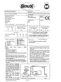
Putting Into Service
Air Supp/y
Use a dean fufcricated air supply that wit ow a measured air pressure
at the loo) of 90 pd.B.2 bar when the tool is running wih the
m'ooef/lever M y dqxessed. Usa recommended hcse size and
lengih. It is recommended that the tool is connected to the air supply
asshewnhfgure 1-Donotconnectihotooltotheairhesystem
vçithouincoporaB'noan easy to reach and operate air dwt off lalve.
The a!f supply should be lubricated. k is strawly recommended that
a\ at ilta-. rmator. lubricator (FPL1i
sused as show) in fiaire 1 as
tvs wH sup& dean. lubricated& at IIW
correct presaura to (ha m L
Oetalsof such equipment can ba obtainedfromwur supplier. 1such
equipment is no! used (hen lha tool should be lubricated by shutting
~fflhaairsupply~lhatod.depress~n.~thefnebypressingthe
(rigger on the tool Disconnect the a r h e aid pour into the intake
bJshira a teaspconfu!(5n-d)of a suitable pneumatic motor lubricating
oil pefefat*/ incofpofiiiiq a rust htih'tw. Reconnect tool to air
w
t
y and run tool do* for a few seconds to allow air to circulate
(he oL If tool is used frequentfylubricateon daily baas and if tool starts
to dow or lose power.
It is recommended that tbe air pressure at the tool whist the tool is
(unning is 90 p.si/6.2 baf. k tool can run at lower and l-igher
pressures with the rnpermitted working air pressure of 100
psi./7 bar.
Operating
-
Select a suitable abrasive belt of the required grade to acrteve a fine
sanded inish or tigh metal removal. The belt size for tMs tool is 20
mm vide K 526 ciccumfefence(continuous belt) and is available in
-
various grades. the lowest is grade 40 grit which is coarse for high
material removal and grits are available as 40.50.60.80. 100 a d
120. The coarseriess of Una grit decreases as the grade number
increases. hence 40 is coarse and 120 wy fine.
To lit a belt. press down Die stopper aid push lha idle puley towards
(he tool until the stopper clicks into place which releases the tension
aid holds (he tension off (he bdL Fit the belt ensuring lhat it sits
centrally on the drive pulleyand the *Hepulley. Release tho stopper to
lighten the belt Start the tool d W and use the adjusting screw{47)
to dig^ the belt centray.
&ply the sanda- i&Uy to the work and allow the bek to cut Take
great care when sanding around sharp edges and comers to avoid
snaggng and belt damage or breakage. It isalways recommended to
use safety glasses and a breathing mask. "Rle sandng of certain
materials may aeate a hazardous dust Wdi may r@re
breathing equipment.Check before using (he tool.
Even if Ihe tool has a low noise level. the actual sandma process vrw
aeate a noise such that hearing protectors should be warn.
f there are shalp edges on the material being sanded ihen safety
doves are recommended.
Do not continue to use belts that are dogged or vmm as this will
make (he sanding process *nefficient and (he need to apcfr
unnecessarilyhigh loads to the tool.
Only use belts of the dimensions specified. To use an incorrect belt
vdl either cause it to break or fly off. Both occurences could be
-
-
Foreseen Use of the Tool
The tod! is designed for tha purpose of cleaning or sanding of
materials using a continuous abrasive beh. Belts are available in
v&om grades to ait fine finislwg or fast materidremoval.
Do not use the tool for any dher purpose than that for which it was
degned. Do not modify this tod for am other use or for its use as a
belt saxkr without fira consultho the manufacturer or the
manufacturersauthoriseddaributor.
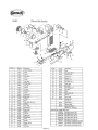
20mm Belt Sander
fief N o
Part N o
1
67313
2
67314
1 Description
Ref No
7
1
8
1
I
67316
,
67317
IValve Body,
1 Throttle Lever
36
I
I
38
1
35
1
1
1 Shoe
1
67342
!Tension Arm
I
67343
1 Stoooer Pin
1
67345
1 Cap Screw (2)
ç
9
66540
Lever Pin
40
67347
Idle Pulley
67318
Deflector
41
67348
Ball Bearing (21 M
11
67319
Air Inlet
42
67349
Idle Shaft
12
67320
Motor Nut
43
67350
45
1
15
-
1
67622
1 Rear Plate
16
67323
Cylinder
17
67324
Rotor
18
67325
Rotor Blade (Set o f 4)
19
67326
Roll Pin
20
67237
Front Plate
21
67328
22
67329
23
I
67330
24
I
67331
26
67333
Wheel Cover
27
67334
Apron
28
67335
Stoooar
67336
Stopper Spring
31
1
I
67337
67338
47
1
I
1
1
67351
67352
67353
67354
1 Counter Sink
1
1
I
,Â¥Orde Qtv. As Needed
Accessory Belts Available (3/4-%20-1
1
1
1
1
I
..
I Roll Pin
I Cap Screw
Collar
-- -
IWheel Cover Lid
IRoll Pin
ICover Latch
Not Shown
1 Washer
1 Lock Nut
Cylinder Pin
30
46
1
Ball Bearing
67332
1
1
1
1 Drive Pulley
25
29
1
1 Description
67339
10
44
1
Part No
ISorina
1
1
1
1
Motor Housing
I
I
I
Page No 3
1
1
1
1
1
1
1
I Belt ResinGoth 60 Grit
IBelt Resin Cloth 80 Grit
1862~~120
1 Belt Resin Cloth 120 Grit
1862RC180 1 Belt Resin Cloth 180 Grit
t862RC240 1 Belt Resin Uoth 240 Grit
1B62RC60
1862RC80
1862VFN
1862MED
1 Belt Surface Conditioning Very Fine
1 Belt Surface Conditioning Medium
Belt Surface Conditioning Course
1
1
1
I
Dismantling & Assembly
Disconnect loo) from air supply
Lift cover(44). press down stoppef(28) 10 reduce tension on the
abrasive belt and push on idle pulley(40) 10 remove belt.
Remove capscrew(38)and washer(37) to remove shoe(32). Take out
2 off scfews(38) and 2 off washers(37) to removs tingaplate(39).
Take out ide shaft screw(42) to release ide pulley assembly. "The ide
pulley assembly may be dismantled by tapping out the bearings(41)
from idle pulley(40) releasing cdlar(43).
Drive out pin(45) to remove whee) cover 1444). Take out 2 off
capscfews(33) to release cover latch(&). PuU out ~ ( 2 7 )Belt
.
alignment countersunk screw may be removed from tenson arm(35)
if a replacement is required.
Drive out stop pin(36) and pull out tension m(36)and spring(34).
Drive out roll pin(=) to release stopper(28) and stopper spring(29).
Insert rod in hole of drive putley(22) to prevent rotation and unscrew
nut(24) with washer(23). Take off drive pullev(22). Note how drive
puIlev(22) locates on pin(19) in rotor( 17).
Unscrew capscrew(31) to remove wheel cover(26). Unscrew air
inlet(11) from motor housing(1) aid take off detector(l0). D r i i out
pin(9) to remove lever(€! Unscrew mfve body(7) and take out
Orinas(6) end (5). valve aem(4)with O-ring@) and -2).
Unscrew motor nut(12) from motor houaing(1) with Mng(13). Tap
carefully. so as not to damage the head. rota(l7) to remove the
motor assemUy Irm rnota housing(1). Rn(19) can be taken cat of
rotod17). Note how the pin(25) in cv(ndarf16) locates the motor
assembly in tho groove in the motor housing(1) and that the pin(25)
is at the rear end plate(l5) end. Hold motor assembly and again tap
the threaded end of the rotd17) to drive it through the front end
p(ate(15) and bearing(14) assembly. Eearina(14) may be lapped out
of front end plalfl5). Take off cylinder(l6) and 4 off rota blactes(18).
Support the rear end plate(l5) in a piece of tube with a bore diameter
as dose as possibleto the mahum diameter of the rotor and tap the
non Dreaded end of the rotor(17) through the rear end plate
assembly. Tap out bearing(21) f r m front plate(20).
Notes
Reassembly
Qean all parts and examine for wear. particularly O-rings. bearings
and rotor blades. Use only dsttibutor or manufacturer supplied spare
parts. Pack all bearings with a general purpose grease and
reassemble h Ihe reverse order. Reft belt and adfist alignment using
screvirf47).
1
Declaration of Conformity
Sioux Tools Inc.
290 1 Floyd Boulevard, P. 0. Box 507, Sioux City, Iowa 5 1102, U.S.A
declare under our sole responsibility that the product
Model 5562 20rnrn Belt Sander, Serial Number
10 uKch iMs declaration relates is n conformityVih the folwhg standard(s)or o h norm&
documantfs)
EM792 (Draft); EN292 Parts 1 & 2, IS0 8662 Parts 1 & 8, Pneurop PN8WC1
fciio~ng(ha prowsions or 89/392/EEC as amended by 9 1/368/EEC& 93/44/EEC Directives
Paoak4
Primed in Japan
12/96