Transcript
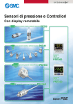
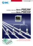
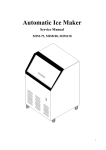
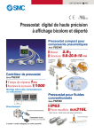
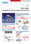
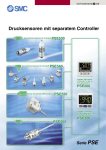
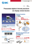
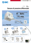
Connector
・ Sensor
Connector Connecting / Disconnecting
Color of Insulation
Brown (DC (+) )
N.C.
Blue (DC (-) )
Black (IN:1 to 5VDC)
PSE200 Series
3 4
1 2
・ Please
29.4
27.2
0.8
Pressure port
13
3
Model No.
37104-3101-000FL
3-1473562-4
XN2A-1430
contact with each connector maker about
PSE300 Series
5
12
5.5
PSE53 - R06
R07
A
45.5
43.3
3.4
Lever
Pressure port
D
checks that the above-mentioned preparation
work has been performed correctly, and A part
shown in right figure is pushed by hand and makes
temporary connection.
・ A part center is straightly pushed in by tools, such as pliers.
・ Re-use cannot be performed once it connects the connector for
sensor connection completely.
・ A sensor connector cannot be taken apart for
reuse once it is crimped.If the wire arrangement
is incorrect or if the wire insertion fails,
use a new sensor connector.
・ When connecting the connector to
PSE200/PSE300 series, please use
the connector for Sensor Lead Wire(ZS-28-C) or
as below.
URL http://www.smcworld.com
3.4
12
7.2
2 1
4 3
Maker
(c)Sumitomo 3M
Tyco Electronics AMP
OMRON
connecting the connector, insert it straight onto the pin
holding the lever and connector body between fingers and lock
the connector by pushing the lever claw into the square groove
in the housing until connector clicks.
・ When disconnecting the connector, push down the lever by
thumb to disengage the lever claw from the square groove.
Then pull the connector straight out.
4
・ It
Thank you for purchasing the SMC PSE530 Series Pressure
Sensor.
Please read this manual carefully before operating pressure
sensor and understand pressure sensor, its capabilities and
limitations. Please keep this manual handy for future reference.
M5
・ When
Connector for Sensor
Lead Wire
Lever
Example of Internal Circuit and Wiring
Model No.
PSE53 -R06
Applicable port size(D)
PSE53 -R07
1/4inch
6mm
Output Specification
Voltage output :
1 to 5V
Output impedance :
Approx. 1kΩ
When connect cable for sensor
Brown DC (+)
1kΩ
Black OUT
(Analog output)
Blue DC (-)
9.8
+
-
10.4
2.7
Pin No.
1
2
3
4
PSE53 -M5
12
7.2
wire is stripped as shown in
Connector
cover
the right figure.
20mm or more
・ The Insulation of the corresponding
color shown in the following table is
put into the pin of the number stamped
Insulation
on the connector for sensor connection to the bottom.
2.5
Attaching the connector to the lead wire
5.4
PSE530 Series
Outline with Dimensions ( in mm )
5.4
Operation Manual
Installation (addendum information)
Main circuit
Pressure Sensor
12 to 24V
DC
catalogue.
SAFETY
Specification
IMPORTANT MESSAGES
Read this manual and follow its instructions. Signal words
such as WARNING and NOTE will be followed by important
safety information that must be carefully reviewed.
Indicates a potentially hazardous situation
which could result in death or serious
injury if you do not follow instructions.
WARNING
Do not disassemble, remodel ( including change of
printed circuit board ) or repair.
An injury or failure can result.
Do not operate beyond specification range.
Fire, malfunction or sensor damage can result.
Do not operate in a combustible gas or explosive
gas atmosphere.
Fire or an explosion can result.
This pressure sensor is not an explosion proof type.
OPERATOR
How to connect the cable for sensor.(Optional)
●This operation manual has been written for those who have
knowledge of machinery and apparatus that use pneumatic
equipment and have full knowledge of assembly, operation
and maintenance of such equipment.
●Please read this operation manual carefully and understand it
before assembling, operating or providing maintenance
service to the pressure sensor.
Pick with fingers the hemale connector of cable for sensor.
Insert it paying attention of connector direction.
Rated pressure range
PSE530-※
PSE531-※
PSE532-※
PSE533-※
0 to 101MPa
0 to -101kPa
0 to 101kPa
-101 to 101kPa
1.5MPa
Withstand pressure
Fluid
Sensor
500kPa
Air, Non-corrosive gases, Incombustible gases
Power supply
Male connector
12 to 24VDC, ripple(p-p)10% or less (Protection against inverse connection)
Current consumption
Analog
output
15mA or less
Voltage: 1 to 5V±2%F.S. or less (Rated pressure range)
Linearity : ±1%F.S. or less Output impedance : Approx.1kΩ
Voltage
output
Repeatability
NOTE
Follow the instructions given below when handling your
pressure sensor. Otherwise, the sensor may be damaged
or may fail, thereby resulting in malfunction.
・Do not drop it, bring it into collision with other objects or apply
excessive shock ( 980m/s2 or more).
・Do not pull the lead wire with force nor lift the main unit by
holding the lead wire. ( Pulling strength less than 23N)
・Do not insert wire nor other article into the pressure port.
・Perform wiring and cable correctly.
・Do not perform wire or cable while power is on.
・Do not wire with the same circuit of power line or high-voltage
line.
・Connect Terminal FG to the ground when using a switching
regulator obtained on the commercial market.
・Keeping from water and dust, set an air tube to the safety
area.
Model No.
Female connector
±1%F.S. or less
Effect form power supply ±1%F.S. or less with standard of analog output at 18V in the range of 12 to 24VDC
Temperature Characteristic
±2%F.S. or less (25℃ reference)
IP40
Enclosure
Cable for sensor have connector cover in order to prevent fall of
female connector. Paying attention for connector cover direction,
install on the sensor, rotate clockwise, and lock it.
To remove cable for sensor, rotate the connector cover anticlockwise, relese lock, and remove connector cover.
After removing connector cover, pick with female connector with
fingers and pull out.
Environment
The Pressure Sensor and this manual contain essential
information for the protection of users and others from possible
injury and property damage and to ensure correct handling.
Please check that you fully understand the definition of the
following messages (signs) before going on to read the text,
and always follow the instructions.
Ambiebt temperature
Operation : 0 to 50℃,Storage :-10 to 70℃ (No condensation, No freezing)
Withstand voltage
1000VAC, 50/60Hz, 1minute (Between lead block and case)
5MΩ or more 500VDC (Between lead block and case)
Insulation resistance
Vibration proof
Impact proof
10 to 500Hz smaller one 1.5mm or 98m/s2 double amplitude, 2 hours each in direction
of X, Y and Z
980m/s2 3times each in directions of X ,Y and Z respectively
Standard
CE MARKING
Cable
Lock
Sensor
Connector cover
Halogen free heavy insulation cable, φ2.7, 0.15mm2, 3wire, 3m
Piping Specification
Model No.
Port size
Unlock
M5
R06
R07
M5×0.8
φ6 Reducer
1/4inch Reducer
Sensor pressure sensing part : Silicon O-ring : NBR
Material
Body : SUS303
Weight
Body : PBT
With cable(3m)
41g
38g
Excluding cable
7g
3.8g