1
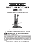
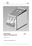
Type Vector®
manual group-operated switch
instruction manual
Installation operation maintenance E50001-F710-A420-X-4A00
Answers for energy.
Arc flash hazard and hazardous voltages.
Will cause death, serious injury or property damage.
Always de-energize and ground the equipment before
maintenance. Read and understand this instruction manual
before using equipment. Maintenance should be performed only
by qualified personnel. The use of unauthorized parts in the
repair of the equipment or tampering by unqualified personnel
will result in dangerous conditions which will cause death, severe
injury or equipment damage. Follow all safety instructions
contained herein.
Important
The information contained herein is
general in nature and not intended for
specific application purposes. It does not
relieve the user of responsibility to use
sound practices in application, installation,
operation and maintenance of the
equipment purchased. Siemens reserves
the right to make changes in the
specifications shown herein or to make
improvements at any time without notice
or obligations. Should a conflict arise
between the general information
contained in this publication and the
contents of drawings or supplementary
material or both, the latter shall take
precedence.
Qualified person
For the purpose of this manual a qualified
person is one who is familiar with the
installation, construction or operation of
the equipment and the hazards involved.
In addition, this person has the following
qualifications:
Is trained and authorized to
de-energize, clear, ground and tag
circuits and equipment in accordance
with established safety procedures.
Is trained in the proper care and use of
protective equipment, such as: rubber
gloves, hard hat, safety glasses or face
shields, flash clothing, etc., in
accordance with established safety
practices.
Is trained in rendering first aid.
2
Further, a qualified person shall also be
familiar with the proper use of special
precautionary techniques, personal
protective equipment, insulating and
shielding materials and insulated tools and
test equipment. Such persons are
permitted to work within limited approach
of exposed live parts operating at 50 volts
or more, and shall, at a minimum, be
additionally trained in all of the following:
The skills and techniques necessary to
distinguish exposed energized parts
from other parts of electric equipment.
The skills and techniques necessary to
determine the nominal voltage of
exposed live parts.
The approach distances specified in
NFPA 70E and the corresponding
voltages to which the qualified person
will be exposed.
The decision-making process necessary
to determine the degree and extent of
the hazard and the personal protective
equipment and job planning necessary
to perform the task safely.
Table of contents
Introduction
4-5
General description
6-7
Receiving, handling and storage
8 - 10
Installation
11 - 12
Operating handle adjustment procedure
13
Operational check out instructions
14 - 15
Maintenance
16 - 17
Note:
These instructions do not purport to cover
all details or variations in equipment, nor
to provide for every possible contingency
to be met in connection with installation,
operation or maintenance. Should further
information be desired or should particular
problems arise that are not covered
sufficiently for the purchaser’s purposes,
the matter should be referred to the local
sales office.
The contents of this instruction manual
shall not become part of or modify any
prior or existing agreement, commitment
or relationship. The sales contract contains
the entire obligation of Siemens Energy,
Inc. The warranty contained in the contract
between the parties is the sole warranty of
Siemens Energy, Inc. Any statements
contained herein do not create new
warranties or modify the existing warranty.
3
Introduction
Arc flash hazard and hazardous voltages.
Will cause death, serious injury or property damage.
Always de-energize and ground the equipment before
maintenance. Read and understand this instruction manual
before using equipment. Maintenance should be performed only
by qualified personnel. The use of unauthorized parts in the
repair of the equipment or tampering by unqualified personnel
will result in dangerous conditions which will cause death, severe
injury or equipment damage. Follow all safety instructions
contained herein.
Arc flash hazard, hazardous voltages and high-speed moving
parts.
Will cause death, serious injury or property damage.
To avoid arc flash burns, electrical shock and entanglement in
moving parts, only qualified personnel should work on or around
this equipment after becoming thoroughly familiar with all
danger or warning notices, and procedures contained herein.
Personnel must observe all applicable regulations (e.g., OSHA),
follow all requirements of NFPA 70E and adhere to specific
operating procedures applicable to the installation. Use
appropriate personal protective equipment (PPE) for the voltage
and arc flash incident energy exposure.
Introduction
The type Vector® manual group-operated
switch is designed to meet all applicable
ANSI, NEMA and IEEE standards.
Successful application and operation of
this equipment depends as much upon
proper installation and maintenance by the
user as it does upon the proper design and
fabrication by Siemens.
The purpose of this instruction manual is
to assist the user in developing safe and
efficient procedures for the installation,
maintenance and use of the equipment.
Contact the nearest Siemens
representative if any additional
information is desired.
4
Introduction
Signal words
The signal words "danger," "warning" and
"caution" used in this instruction manual
indicate the degree of hazard that may be
encountered by the user. These words are
defined as:
Danger - Indicates an imminently
hazardous situation which, if not avoided,
will result in death or serious injury.
Warning - Indicates a potentially
hazardous situation which, if not avoided,
could result in death or serious injury.
Caution - Indicates a potentially hazardous
situation which, if not avoided, may result
in minor or moderate injury.
Field service operation and warranty
issues
Siemens can provide competent, well
trained field service representatives to
provide technical guidance and advisory
assistance for the installation, overhaul,
repair and maintenance of Siemens
equipment, processes and systems.
Contact regional service centers, sales
offices or the factory for details, or
telephone Siemens field service at
+1 (501) 362-8296.
For medium voltage customer service
issues, contact Siemens at +1 (501) 3628296.
Caution (without safety alert symbol) Indicates a potentially hazardous situation
which, if not avoided, may result in
property damage.
5
General description
Introduction
Siemens type Vector® manual groupoperated air switch is precision built
equipment designed to function efficiently
under normal operating conditions. It is
designed and manufactured to operate
within the parameters established in ANSI/
IEEE and NEMA standards for
disconnecting and load-interrupter
switches. Performance requirements of
these standards have been met or
exceeded by these designs. Specific
standards which apply include:
ANSI/IEEE C37.30 Requirements for
High-Voltage Switches
ANSI/IEEE C37.32 High-Voltage
Switches, Bus Supports and Accessories
- Preferred Ratings, Construction
Guidelines, and Specifications
ANSI/IEEE C37.34 Test Code for HighVoltage Air Switches
Figure 1: Typical type Vector manual group-operated switch
ANSI/IEEE C37.35 Guide for the
Application, Installation, Operation and
Maintenance of High-Voltage
Disconnecting and Interrupter Swiches
ANSI/IEEE 1247 Interrupter Switches for
Alternating Current, Above 1,000
NEMA SG6 Power Switching
Equipment.
The instructions included in this instruction
manual are provided to aid you in
obtaining longer and more economical
service from your Siemens type Vector
manual group-operated air switch. For
proper installation and operation, this
information should be distributed to your
operators and engineers.
By carefully following these instructions,
difficulties should be avoided. However,
these instructions are not intended to
cover all details of variations that may be
encountered in connection with the
installation, operation and maintenance of
this equipment.
Should additional information be desired,
including replacement instruction
manuals, contact your local Siemens
representative.
6
General description
Scope
These instructions cover the installation,
operation and maintenance of a Siemens
type Vector® manual group-operated air
switch. The equipment designs described
in this instruction manual consists of
group-operated air switch for application
up to 38.0 kV. A typical type Vector manual
group-operated air switch is shown in
Figure 1. All diagrams, descriptions and
instructions apply to all of the above
classes and designs unless noted
otherwise.
The equipment furnished has been
designed to operate in a system having the
circuit capacity specified by the purchaser.
If for any reason the equipment is used in
a different system or if the short-circuit
capacity of the system is increased, the
ratings of the equipment, including the
momentary rating and the interrupting
capacity of the type Vector manual groupoperated air switch must be checked.
Failure on the part of the user to receive
approval of intended changes from
Siemens may cause the warranty to be
void.
Design
Type
Manual groupoperated switch
Vector
Table 1: Type Vector manual group-operated air
switch
General description
Siemens type Vector manual groupoperated air switch carries a type
designation, as shown in Table 1: Type
Vector manual group-operated air switch.
This designation may appear on drawings
and familiarity with them will simplify
communications with the factory.
7
Receiving, handling and storage
Receiving
Pipe guide assembly
Each type Vector® manual group-operated
air switch is securely blocked and braced
for shipment on a pallet. It is crated, boxed
or covered as required by shipping
conditions. If special handling is required,
it is so indicated. The type Vector manual
group-operated air switch must be handled
carefully when unloading.
Inspection and unpacking
Lock segment assembly
Pipe guide assembly
Handle assembly
Inspect the equipment as soon as possible
after receipt for any damage that may have
occurred in transit. Before unpacking,
examine the package itself, as a damaged
package may indicate damage to the
contents of the package. Be careful when
unpacking equipment. The use of sledge
hammers and crowbars may damage the
finish, or the equipment itself. Use nail
pullers. After unpacking, examine
equipment for any possible damage. Check
the shipping manifest to be certain that all
items have been received. If there is a
shortage, make certain it is noted on the
freight bill and contact the carrier
immediately. Notify Siemens mediumvoltage customer service at +1 (501) 3628296 of any shortage or damage.
The palletized type Vector air switch
system includes the following components
and assemblies (refer to type Vector
assembly drawing for exact bill of
materials):
Insulator assembly (optional)
completely assembly and factory
1. A
adjusted three-phase air switch.
2. Pipe bundles:
Note: Pins and cotter pins not
shown
Figure 2: Hardware box images
8
a) Vertical operating pipe
(seven-foot long sections)
b) Universal joint assembly
(steel pipe or fiberglass).
3. Hardware box:
P
ipe guide assembly
a)
b)
Lock segment assembly
c)
Coupling assembly
d)
Handle assembly
e)
Insulator assembly (optional)
f)
Pins
g)
C
otter pins.
4. Documentation package:
A
ssembly drawing
a)
Air switch unit drawing
b)
This instruction manual.
c)
Shipping damage claims
Important: The manner in which visible
shipping damage is identified by consignee
prior to signing the delivery receipt can
determine the outcome of any damage
claim to be filed.
Notification to carrier within 15 days for
concealed damage is essential if loss
resulting from unsettled claims is to be
eliminated or minimized.
1. When shipment arrives, note whether
equipment is properly protected from
the elements. Note trailer number on
which the equipment arrived. Note
blocking of equipment. During
unloading, make sure to count the
actual items unloaded to verify the
contents as shown on the delivery
receipt.
2. M
ake immediate inspection for visible
damage upon arrival and prior to
disturbing or removing packaging or
wrapping material. This should be
done prior to unloading when possible.
When total inspection cannot be made
on vehicle prior to unloading, close
inspection during unloading must be
performed and visible damage noted
on the delivery receipt. Take pictures if
possible.
Receiving, handling and storage
3. A
ny visible damage must be noted on
the delivery receipt and acknowledged
with the driver’s signature. The
damage should be detailed as much as
possible. It is essential that a notation
"possible internal damage, subject to
inspection" be included on delivery
receipt. If the driver will not sign the
delivery receipt with damage noted,
the shipment should not be signed for
by the consignee or their agent.
4. Notify Siemens immediately of any
damage at +1 (501) 362-8296.
5. Arrange for a carrier inspection of
damage immediately.
Important: Do not move equipment from
the place it was set when unloading. Also,
do not remove or disturb packaging or
wrapping material prior to carrier damage
inspection. Equipment must be inspected
by carrier prior to handling after receipt.
This eliminates loss due to claims by carrier
that equipment was damaged or further
damaged on site after unloading.
6. Be sure equipment is properly
protected from any further damage by
covering it properly after unloading.
7. If practical, make further inspection for
possible concealed damage while the
carrier’s inspector is on site. If
inspection for concealed damage is not
practical at the time the carrier’s
inspector is present, it must be done
within 15 days of receipt of equipment.
If concealed damage is found, the
carrier must again be notified and
inspection made prior to taking any
corrective action to repair. Also notify
Siemens immediately at +1 (501) 3628296.
8. O
btain the original of the carrier
inspection report and forward it along
with a copy of the noted delivery
receipt to Siemens at +1 (501) 3628296. Approval must be obtained by
Siemens from the carrier before any
repair work can be performed. Before
approval can be obtained, Siemens
must have the above referenced
documents. The carrier inspection
report and/or driver’s signature on the
delivery receipt does not constitute
approval to repair.
Note: Any determination as to whether the
equipment was properly loaded or properly
prepared by shipper for over-the-road
travel cannot be made at the destination.
Shipments are not released from the
factory without a clear bill of lading.
Approved methods are employed for
preparation, loading, blocking and tarping
of the equipment before it leaves the
Siemens factory. If the equipment is
received in a damaged condition, this
damage to the equipment has to have
occurred while en route due to conditions
beyond Siemens‘ control. If the procedure
outlined above is not followed by the
consignee, purchaser or their agent,
Siemens cannot be held liable for repairs.
Siemens will not be held liable for repairs
in any case where repair work was
performed prior to authorization from
Siemens.
9
Receiving, handling and storage
Lifting and moving
There are a number of methods that can
be used in handling the type Vector®
manual group-operated switch that, when
properly employed, will not damage the
type Vector manual group-operated
switch. The handling method used will be
determined by conditions and available
equipment at the installation site.
The lifting method used in handling the
type Vector manual group-operated switch
is achieved via the single point hoist
bracket. When properly employed, this
method of handling will not damage the
type Vector manual group-operated
switch.
Forklift trucks may be used prior to
removal of wooden skids. Verify the forklift
blades pass completely through the
wooden skid underneath the type Vector
manual group-operated switch.
Lifting type Vector manual groupoperated switch with crane
Recommended lifting of type Vector
manual group-operated switch is by means
of cable connected to an overhead crane
or bucket truck. The cable is connected to
the single-point lift bracket on the top of
the type Vector manual group-operated
switch.
Storage
If at all possible, install the type Vector
manual group-operated switch at the
permanent location even though it may be
some time before the equipment is used. It
is also recommended that the type Vector
manual group-operated switch receive
periodic inspection during storage.
Each type Vector manual group-operated
switch has a provision for attaching lifting
cables. The single point hoist bracket is
installed on the tested balance point of the
type Vector group-operated switch. Refer
to the type Vector group-operated switch
nameplate for the weight.
Heavy weight.
Can result in death, serious injury or property damage.
Observe all handling instructions in this instruction manual to
prevent tipping or dropping of equipment.
10
Installation
Installation
Installation instructions for the type Vector
manual group-operated air switch are
detailed in the following steps:
A
1. Drill two mounting holes 11/16" in
diameter located per the user's
construction standards and spaced per
Siemens assembly drawing.
2. Install the mounting bolts in the holes.
Mounting bolts to be furnished by
others.
3. Using the single-point lift bracket, lift
the air switch approximately 4' (1.2 m)
off of the ground (Refer to Figure 3:
Single-point lift bracket)
Item
Description
A
Single-point lift bracket
Figure 3: Single-point lift bracket
Note: Be careful when handling the air
switch not to damage the interrupters or
current-carrying parts.
4. Cut the hinge ties on each phase of the
air switch.
5. If surge arresters (supplied by others)
are required, some users prefer to
mount and make-up the surge arresters
at this step.
A
Item
Description
A
16" ( 496 mm) extension link
Figure 4: Extension link
It is the user's responsibility to adjust
arrester brackets, arresters, ground lead
wires and hot lead wires to provide proper
phase-to-ground and phase-to-phase
clearance.
6. E
xtension links (supplied by others)
(refer to Figure 4: Extension link) are
required on the jaw side of the air
switch only, if dead ending on the air
switch unit. Some users prefer to install
the extension links at this step.
7. L ift the air switch unit and mount it on
the pole, over the previously installed
mounting bolts and tighten bolts.
Keyhole slots for this purpose have
been machined in the mounting
channel. Remove blade ties from all
three jaw assemblies so that the air
switch can be operated.
11
Installation
A
EN
A
Item
Description
A
Loosen bolt
A
CL
O
SE
D
OP
A
Figure 5: Loosen bolts
8. Remove single-point lift bracket.
9. G
round the air switch unit (and surge
arresters if required) using #2 or larger
copper wire. A grounding point (1/2-13
tapped hole) is provided in the side of
the mounting bracket (refer to
assembly drawing provided).
10. Mount pipe guides and lock segment
assemblies in position per user's
construction standard or assembly
drawing using one through bolt and
one lag bolt each. Tighten the through
and lag bolt.
Note: The pipe guides and lock segment
are adjustable. Loosen the bolts such that
the pipe guides and lock segment can slide
in the slots (refer to Figure 5: Loosen
bolts).
11. Install vertical operating shaft sections
and universal joint as shown on the
assembly drawing using pins, cotter
keys, coupling assemblies (if required)
and insulator assembly (if required).
Before placing bottom shaft section in
the lock segment, place the operating
handle assembly loosely in position.
12
Note: Verify the piercing set screws are
backed out all the way before sliding the
handle assembly on the bottom shaft
section (refer to Figure 6: Before piercing).
Before piercing
A
Item
Description
A
End of piercing set screws must
not extend beyond this surface.
Figure 6: Before piercing
12. Excess pipe should be removed if
required. Leave at lease 1' (.3 m) of
pipe extending below the lock
segment assembly.
Operating handle adjustment procedure
Operating handle adjustment procedure
The next series of steps address adjusting
the position of the handle assembly and
lock segment assembly so that the handle
can be inserted into the OPEN and CLOSED
slot correctly.
Important: It is extremely important to
adjust the handle position so it is
impossible to place the operating handle in
the CLOSED slot unless the air switch
blades are fully closed. An operator may
not be able to check the blades visually to
verify the air switch is fully closed at night
and/or under severe weather conditions.
Therefore, it should take considerable
wind-up (torsion) of the vertical pipe to
get the handle in position to force it into
the CLOSED slot. Remember that as the air
switch gets older, it will become harder to
operate and more force will be required on
the operating handle to completely close
the air switch. The operator must apply
sufficient force to completely close the
air switch.
1. Adjust the CLOSED and OPEN segments
on the lock segment assembly such
that they are approximately 90°/100°
apart, with adjustment still left in the
slots in each direction. Tighten the
bolts loosened under Installation
instructions item 10 on page 12.
Note: Before tightening bolts, put the end
of the ground strap from the handle
assembly under the flat washer on the
bolt. Leave enough slack in the ground
strap to allow the operating handle to
travel fully from the OPEN position to the
CLOSE position without any interference
(refer to Figure 7: Operating handle).
2. The handle casting should be mounted
4" (102 mm) to 6" (152 mm) above the
lock segment assembly. Position the
handle casting so that with the air
switch closed (blades tight against the
spacer), the operating handle will
strike point A on the lock segment
assembly when the operating handle is
lowered (refer to Figure 7: Operating
handle). This will assure that when the
air switch is fully closed, it will take
considerable wind-up torque to get the
operating handle into the CLOSED slot
on the lock segment assembly.
ighten the four clamp bolts. Do not
3. T
tighten the piercing set screws yet.
Open and close the air switch slowly
and then rapidly. Check for a smooth
operation of the air switch. Adjust the
pipe guides for a smooth, non-binding
operation and tighten down both bolts
in each pipe guide assembly. Make sure
that the air switch can be fully opened
and fully closed (blade tightly up
against the jaw contact spacer on all
three phases).
4. Verify that the air switch handle will
strike point A of the lock segment
assembly and that considerable windup torque is needed to get the air
switch operating handle into the
CLOSED slot of the lock segment
assembly.
5. If needed, reposition the handle
casting by loosening and re-tightening
the four clamp bolts until the operation
of the air switch meets the
requirements described in steps 3, 4
and 5. Adjustments may also be made
by moving the lock segment slightly on
the lock segment assembly.
fter the handle casting is in the final,
6. A
properly adjusted position, verify the
four clamp bolts are fully tightened.
Then, tighten both piercing set
screws until each screw pierces
through the wall of the pipe.
A
B
Item
Description
A
Point A
B
Operating handle
Figure 7: Operating handle
After piercing
A
Item
Description
A
Slug from pierced
pipe
Figure 8: Before piercing
Note: When tightening these piercing set
screws, the resistance will keep increasing
and then will drop off sharply once the
pipe is pierced. Fully tighten the piercing
set screws until the shoulder of the
piercing set screw is firmly placed against
the pipe (refer to Figure 8: After piercing).
7. The piercing set screws help assure
that when the air switch handle is
thrown open or closed, the vertical
pipe will definitely rotate with the
handle.
8. G
round the lock segment/handle
assembly to the pole ground using a #2
or larger flexible copper wire (refer to
Figure 9: Grounding).
A
A
B
C
Item
Description
A
#2 pole ground wire
or larger
B
Split-bolt connector
C
Pole
Figure 9: Grounding
13
Operational check out instructions
Operational check out instructions
A
C
D
C
D
B
Item
Description
A
Spacer
B
Blade
C
Contacts
D
Auxiliary contacts
Figure 10: Blade
A
Item
Description
A
Air gap
1/8" (3.2 mm)
Operational check out instructions for the
type Vector® manual group-operated
switch are detailed in the following steps:
1. S
witches are fully adjusted and
inspected before they leave the
factory. There should be no need to
adjust the switch unit.
2. C
heck the rotation of the hinge
terminals. They should rotate
approximately 180° with slight
resistance.
3. T
he following checks should be
performed independently on all three
phases to verify proper operation of
the switch and interrupters. This will be
performed manually.
a) Close the switch fully and lock the
operating handle into the CLOSE
position of the lock segment. Bounce
the blade toward the OPEN position.
The blade should remain tightly
against the stop. If the blade does
not remain tightly against the stop,
re-adjust the handle/lock segment
assembly per the Operating handle
adjustment procedure presented on
page 13. Refer to Figure 10: Blade.
b) With the switch still fully closed and
the interrupter cocked (set to trip),
the lever should stick above the
nylon bumper at least 1/8"
(3.2 mm). There should be no metalto-metal contact between the
interrupter's lever and the contact
casting. The lever should rest in the
air gap as shown in Figure 11: Air
gap. Raise the interrupter lever and
verify the lever clears without
touching any metal.
c) Slowly open the switch and verify
the following operations occur:
1.
As the blade opens, the bottom
of the blade touches the
auxiliary contacts before the
main blade leaves the main
contacts (refer to Figure 12:
Blade movement, detail A). This
transfers the load from the
main contacts to the auxiliary
contacts. As the switch
continues to open, the main
contacts will part and no longer
carry the load, while the
auxiliary contacts carry the full
load (refer to Figure 12: Blade
movement, detail B).
Figure 11: Air gap
Figure 12: Blade movement
Detail B
Detail A
A
14
C
B
C
D
A
C
C
D
Item
Description
Item
Description
A
Spacer
C
Contacts
B
Blade
D
Auxiliary contacts
D
B
D
Operational check out instructions
2. As the blade continues to rotate
open, the interrupter lever
must make full metal-to-metal
contact with the contactor
(refer to Figure 13: Contactor
connection). At this point, the
load then transfers from the
auxiliary contacts to the
interrupter's lever arm so that
the interrupter now carries the
full load.
3. As the blade continues to rotate
open, the interrupter will trip
thus interrupting the load. The
interrupter must trip while the
lever arm is in metal-to-metal
contact with the contactor. The
interrupter should trip (fire)
before the contactor is within
1/2" (12.7 mm) to 3/4" (19 mm)
of the end of the lever (refer to
Figure 14: Contactor space).
4. Continue to open the switch
until the interrupter lever has
cleared the end of the nylon
push bar, the lever will spring
back slightly. This allows the
nylon bumper of the contactor
assembly to engage the lever
and lift the lever into position,
when the switch is being
closed. Open the switch fully.
4. Now, close the switch slowly. The
following operations and checks
should be made:
A
A
Item
Description
A
Contactor
Figure 13: Contactor connection
Description
A
1/2" (12.7 mm) to
3/4" (19 mm)
Figure 14: Contactor space
A
A
B
Item
Description
Item
Description
A
1/2" (12.7 mm) to 3/4" (19 mm)
A
B
Nylon push bar
1/2" (12.7 mm) to
3/4" (19 mm)
Figure 15: Lever pick up
a) As the blade rotates closed, the push
bar must pick up the lever at least
1/2" (12.7 mm) from the end of the
lever (refer to Figure 15: Lever pick
up).
d) In the fully closed position, the lever
should rest on the bumper, and stick
above the bumper at least 1/8"
(3.2 mm) (refer to Figure 17: Lever
position).
b) Continue to close the blade, when
the lever is at 90° to the interrupter,
the push bar should be at least 1/2"
(12.7 mm) from the side of the yoke.
At no time during the closing of the
switch should the push bar touch
the connecting rod or yoke (refer to
Figure 16: Push bar).
e) T
hese adjustment checks should be
repeated on each independent
switch blade/phase.
c) Close the switch completely and
verify that the interrupter resets
(cocks) for the next opening
operation.
Item
5. T
he switch is now ready for installation
of the conductors.
Figure 16: Push bar
A
B
Item
Description
A
Air gap
B
Bumper
Figure 17: Lever position
15
Maintenance
Maintenance
Maintenance instructions for the type
Vector® manual group-operated switch are
detailed in the following steps:
1. P
eriodically operate the switch and
check for actions described in
Operational check out instructions on
pages 14-15. Lubricate the jaw,
auxiliary contacts and the end of the
blade with Dow Corning® Molykote FS1292 white grease.
2. W
ith the handle in the CLOSED position
of the lock segment, verify that the
switch is fully closed and there is windup torque on the operating pipe. If not,
readjust the operating handle and/or
the lock segments per Operating
handle adjustment procedure on page
13.
efer to ANSI/IEEE C37.35 guide for the
3. R
application, installation, operation and
maintenance of high-voltage airdisconnecting and load-interrupter
switches for additional
recommendations.
16
Maintenance
Table 2: Remarks
17
Published by and copyright © 2011:
Siemens AG
Energy Sector
Freyeslebenstrasse 1
91058 Erlangen, Germany
Siemens Energy, Inc.
99 Bolton Sullivan Drive
Heber Springs, AR 72543
For more information, contact
+1 (800) 347-6659
+1 (501) 362-8296
Order No. E50001-F710-A420-X-4A00
Replaces No. VEC4100 10/2/08
Printed in USA
All rights reserved.
Trademarks mentioned in this document
are the property of Siemens AG, its affiliates,
or their respective owners.
Subject to change without prior notice.
The information in this document contains
general descriptions of the technical options
available, which may not apply in all cases.
The required technical options should therefore
be specified in the contract.
www.usa.siemens.com/energy