1
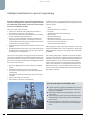
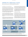
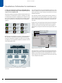
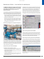
© Siemens AG 2011
Products and functions for
efficient maintenance in the
process automation
Brochure · October 2011
Maintenance System
Answers for industry.
© Siemens AG 2011
Introduction
Increase in productivity through intelligent maintenance
Intelligent maintenance strategies can make a significant contribution toward increasing productivity:
• Failures can be prevented by monitoring the current plant
condition.
• Maintenance can then be planned. It does not wait until a
fault has occurred, but implements appropriate measures
in advance for avoiding faults. The timing of maintenance
can be planned such that the existing resources can be
used optimally.
• Innovative maintenance strategies pay for themselves
twice: planning security and the specific application of methods reduces the direct maintenance costs.
• Plant availability is increased at the same time. This means
that consequential costs resulting from failures, such as
quality deficiencies or loss of image, are reduced.
Totally Integrated Automation supports intelligent maintenance strategies. The SIMATIC Maintenance Station is of significant importance, and presents the information relevant to
maintenance from all automation components in a uniform
and clear manner, thus providing the maintenance engineer
with valuable support for making decisions.
Maintenance strategies
There are two maintenance strategies: response to failures or
taking preventive measures. In the case of failure-oriented
corrective maintenance, measures are only initiated when a
fault has occurred, i.e. failures are acceptable in this case and
may be minimized by a redundant plant design.
The objective of preventive strategies is to carry out maintenance measures before faults even occur, in order to avoid
possible downtimes. This strategy can be satisfied using
time-dependent and load-dependent measures. Regular
maintenance work is an example of time-dependent measures. The load state is determined from the number of switching operations, operating hours or load peaks.
2
Introduction
Benefits of intelligent maintenance
Continuous plant monitoring
■
■
Reduces the risk of failures, and increases the
availability
Enables maintenance to be planned
Optimized use of maintenance resources
■
■
Increases maintenance quality
Achieves cost savings
The potential for savings arises
■
■
During maintenance itself and
by avoiding consequential costs
Condition Monitoring, that is to say status monitoring, aims
to detect imminent faults at an early stage. It provides information on the remaining duration of use. In the case of condition-based maintenance, the maintenance measures are
only initiated when the period of use has expired.
It has been shown in practice that optimum results can be
achieved through intelligent combination of the different strategies.
Maintenance
Corrective
Preventive
Time-dependent
Load-dependent
Condition-based
Maintenance strategies
G_ST80_XX_00410
How can the productivity of a plant with a high level of automation be increased even further?
Plant operators in all sectors consider increased availability and shorter downtimes to be the most effective lever toward increasing productivity. Investigations have shown
that downtimes are frequently the result of insufficient
maintenance – despite the fact that maintenance is already a significant portion of the lifecycle costs.
© Siemens AG 2011
Contents
Text
Introduction
Increase in productivity through
intelligent maintenance . . . . . . . . . . . . . . . . . . . . . . . 2
Plant-level asset management as a
maintenance task . . . . . . . . . . . . . . . . . . . . . . . . . . . . 4
Intelligent maintenance
in process engineering . . . . . . . . . . . . . . . . . . . . . . . . 6
SIMATIC PCS 7 Maintenance Station
More productivity with
Totally Integrated Automation . . . . . . . . . . . . . . . . . . . 7
Visualization of information
for maintenance . . . . . . . . . . . . . . . . . . . . . . . . . . . . . 8
Maintenance Station –
User interface for maintenance . . . . . . . . . . . . . . . . . . 9
Add-ons as options for the SIMATIC PCS 7
Maintenance Station . . . . . . . . . . . . . . . . . . . . . . . . . 12
Monitoring and diagnostics
for industrial PCs . . . . . . . . . . . . . . . . . . . . . . . . . . . . 13
of networks . . . . . . . . . . . . . . . . . . . . . . . . . . . . . . . . 14
for process instrumentation and analytics . . . . . . . . 16
for positioners and control valves . . . . . . . . . . . . . . . 21
of 24 V load feeders . . . . . . . . . . . . . . . . . . . . . . . . . . 22
of wear in the motor. . . . . . . . . . . . . . . . . . . . . . . . . . 22
of drive components. . . . . . . . . . . . . . . . . . . . . . . . . . 25
Plant-level asset management with
Totally Integrated Automation components . . . . . . . 27
Introduction
3
© Siemens AG 2011
Plant Asset Management as a maintenance task
General information
Various tasks have to be handled during the operating phase
of a plant, for which different groups of persons are responsible.
The production personnel operate and monitor the plant, and
make sure that the desired products are produced with the appropriate quality, in the defined quantity, at a specified time,
and with minimum resources with respect to personnel, raw
materials, energy, costs, etc.
Maintenance staff must
• ensure a high availability of the plant,
• ensure this availability in the long term by implementing
optimization measures, and
• carry out maintenance measures with minimum use of personnel, material, energy, costs, etc.
As a result of their different tasks, these two groups of persons
have different information requirements.
Different demand for information at the plant
Plant operator
Information on the process such as:
• Recipe parameters
• Temperature characteristic
• Pressure values
• Raw material stocks
• Output
Maintenance personnel
Information on the state of the production equipment such as:
• Components OK
• Maintenance required
• Failure
• Functional check
4
Introduction
Information on the measured process tags is available for the
plant operator. Apart from the measured value itself and its
status, this may, for example, be the information on whether
the measured value is still valid.
The focus of interest for the maintenance engineer is the status of the production equipment that is reflected in the states
of the devices and components used (i.e. particularly in the
states of the field devices). Typical states in this respect include "Component OK", "Maintenance required", "Failure" or
"Function check".
SIMATIC PCS 7 allows a clear classification of the information
for the user groups Plant Operators and Maintenance Engineers.
© Siemens AG 2011
Asset management in production
Benefits of Plant Asset Management
The term asset management comes from the world of finance
and economics and refers to the manner in which a company
deals with its long-term and current assets. These include the
production equipment with its plant components such as apparatus, machines, pipelines etc. and the equipment and devices for their automation. All these are referred to as assets.
In association with production, asset management covers all
activities and measures which serve toward retaining or increasing the value of a plant. This is called Plant Asset Management.
Plant Asset Management allows the maintenance engineer
• to unambiguously identify and evaluate the assets, this means the production equipment and its components;
• to carry out the appropriate measures in the case of deviations from the desired or expected state.
As a result of monitoring, i.e. the recording and evaluation of
status variables, the condition of a component or device can
be determined.
It can be recognized, for example, that no signal is received
from the sensor, resulting in the diagnosis "Open circuit". This
result triggers a maintenance request, and maintenance must
then be carried out to eliminate the open circuit.
This measure – replacement of a faulty line in this example –
ensures that the component is returned to the desired condition and closes the maintenance cycle. This means that Plant
Asset Management is the basis for increased productivity.
Maintenance
measure
Maintenance
request
Monitoring
Diagnostics
Introduction
5
© Siemens AG 2011
Intelligent maintenance in process engineering
Despite the different tasks of operators and maintenance
staff, it is meaningful and necessary to map the information of both staff groups within one process control system
and not to use different systems.
There are various reasons for this:
• Uniform visualization for all components and devices.
• No limitation to selection of field devices.
• The same information sources (field devices) are relevant
to both automation and maintenance.
• There is a close link between automation and asset management functions because, for example, the current
control strategy of the plant plays an important role for the
assessment of a component status.
• Engineering data for automation can also be used for maintenance.
• Simplified handling of the system, since users need only be
acquainted with the engineering, operator control and monitoring tools of a single system.
The process control special interest group of the pharmaceuticals industry (NAMUR) has formulated essential requirements
(NE 91) from the user's viewpoint. This attaches special significance to the integration of the Plant Asset Management into
the process control system.
• Plant Asset Management is a part of the process control
system
• Recording and assessing the status of the assets
• Inclusion of all assets (process control devices and plant
components)
• Separation of maintenance-relevant information and process data
• Uniform visualization for all assets
• No limitation to selection of field devices
In addition, there is a requirement (NE 107) that all field devices must provide standardized status messages about their
status as follows:
• Good
No known restriction of function
• Uncertain
Operation outside the specified range
• Device failure
Need for maintenance
• Maintenance required
Function check (process value manipulated)
• Function check, local operation
Failure (process value invalid)
Processing plants, whose open and closed loop control is performed with SIMATIC PCS 7 and components of Totally Integrated Automation, satisfy the user requirements formulated
by NAMUR.
The resulting information is divided up to prevent the plant
operators and maintenance staff from being flooded with information. To achieve this, a Maintenance Station (MS) is introduced in addition to the operator station (OS). Maintenance-relevant information is kept away from the operator
station. This information is collected and presented on the
Maintenance Station. The same HMI tools are used for the
operator station and the Maintenance Station and the HMI
philosophy is identical.
Plant Asset Management with SIMATIC PCS 7
■
■
■
■
6
Introduction
Process engineering plants with SIMATIC PCS 7 and components of Totally Integrated Automation meet the requirements of NAMUR.
Automation and Plant Asset Management run on the
same system.
The information for plant operators maintenance staff is
divided between the operator station and the Maintenance Station.
Shared configuration and uniform user interfaces minimize the expense of an effective Plant Asset Management.
© Siemens AG 2011
SIMATIC PCS 7 Maintenance Station
More productivity with Totally Integrated Automation
Integrated plant and cross-system maintenance
Plant Asset Management is only truly productive if maintenance staff can view diagnostic information relating to the entire process chain. In practice, this means that the same maintenance team that is responsible for the actual process can
support inbound and outbound processes such as logistics,
bottling and packaging plants without having to build up a
great deal of additional expertise. If the process control system and the controllers of the upstream and downstream systems originate from different vendors, different alarm systems can cause considerable additional expense.
If a plant is automated with SIMATIC PCS 7, therefore it is worthwhile for the plant operators to select machines and systems that are automated with SIMATIC and visualized with
SIMATIC WinCC for their inbound and outbound processes, as
then they can exploit all the advantages of Totally Integrated
Automation.
If machines or systems for inbound/outbound processes are
operated and monitored by means of SIMATIC WinCC, then
the SIMATIC Maintenance Station presents itself as an option
to SIMATIC WinCC for maintenance-relevant information.
The integrated functionality of Totally Integrated Automation
also makes it possible, using the SIMATIC PCS 7 Maintenance
Station, to monitor the packaging or bottling line by means of
a client. Display, logic, and message management are identical. The uniform look and feel saves on overhead and generates a high degree of acceptance within the maintenance
team. The SIMATIC Maintenance Station for SIMATIC PCS 7
and SIMATIC WinCC makes a significant contribution to increasing maintenance productivity and thus to increasing the
availability of the overall plant.
Optimizing instead of repairing
The task of maintenance is not only to avoid unscheduled production downtimes, but also to optimize the running of the
plant. Optimization must be based on analysis of traceable
processes. The Maintenance Station offers the basic data set
for integrated analysis of all weak points. This is not unusual
in a process control system. However, in inbound and outbound processes diagnostics are often restricted to signaling
a fault and then forgetting about it as soon as it has been repaired. With Totally Integrated Automation, the Maintenance
Station becomes the basis for Total Productive Maintenance.
Central control room with plant-wide maintenance overview
Maintenance
Station Client
,QWHUQHW
Maintenance
Station Client
+ Web Server
Inbound process
Maintenance Station
Server SIMATIC PCS 7
Productions process
Maintenance Station
Server (WinCC)
Outbound process
G_ST80_XX_00337
Maintenance Station
Server (WinCC)
SIMATIC Maintenance Station: Collecting diagnostic information from the entire process chain centrally – even via the Web
Suitable protective measures (among others IT-Security, e.g. network segmentation) have to be taken up to ensure a safe operation of the plant.
You find further information about the topic of Industrial Security on the Internet under www.siemens.com/industrialsecurity.
SIMATIC PCS 7 Maintenance Station
7
© Siemens AG 2011
Visualization of information for maintenance
In order to recognize the conditions of individual devices
or components unequivocally, a uniform symbol representation has been implemented.
There are symbols for the device status itself and also for the
importance of a maintenance request. In addition, the status
of a maintenance measure is displayed. The conditions of all
devices and equipment of the automation technology and of
the plant components are indicated by these standardized
symbols.
*RRG
0DLQWHQDQFH
UHTXLUHPHQW
ORZ
0DLQWHQDQFH
MREXQNQRZQ
QRWUHTXHVWHG
6LPXODWLRQ
0DLQWHQDQFH
UHTXHVW
DYHUDJH
0DLQWHQDQFH
MRE
UHTXHVWHG
/RFDORSHUDWRU
FRQWURO
0DLQWHQDQFH
DODUP
KLJK
0DLQWHQDQFH
MRE
EHLQJSURFHVVHG
The overview display uses the standardized symbols to visualize the condition of a component itself and also provides collective information on the conditions of all devices in the subordinate hierarchies.
The collective condition message shows the OK condition or
the seriousness of a possible problem in red, yellow, or green,
as per a traffic light. A button can be used to access all subordinate hierarchy levels step-by-step down to the bottom device level.
Further views of the maintenance information are available in
addition so that the maintenance engineer has a complete
overview of all current information of the asset relevant to
maintenance. This permits assessment of the plant status at a
glance.
Maintenance group display
Maintenance state display
Operate state display
Uniform symbols for the conditions of components and devices
Besides the uniform display of symbols, a significant detail for
the overview is a hierarchical structuring of information in
which the maintenance engineer also has access to all required details of the components and devices, based on an overview display (plant view).
Identification of device
Plant view
G_ST80_XX_00421
Detailed view of a component
The information is consistently structured and hierarchically
organized. The quantity of information displayed on each individual screen always remains manageable for the maintenance engineer, who nevertheless has easy access at any time
to the complete information.
Overview
Automation
system (AS)
AS rack
2...n
Subnet
Detailed view
Component/
Device
Extract from the hierarchical visualization of the maintenance
information
8
SIMATIC PCS 7 Maintenance Station
G_ST70_XX_00413
AS rack
1
© Siemens AG 2011
Maintenance Station – User interface for maintenance
The SIMATIC PCS 7 Maintenance Station software package
is available as an alternative to SIMATIC PCS 7 for implementing Plant Asset Management. You can use this software package to expand an Operator Station to a
Maintenance Station.
The maintenance engineer can process the diagnostics messages and maintenance requests of the assets on the Maintenance
Station. Via the Maintenance Station the engineer can access:
• Electronic components of the process control system: intelligent field devices and I/O modules, field bus, controller,
network components and plant bus as well as servers and
clients of the operator systems.
• Mechanical components that do not belong directly to the
process control system such as pumps, motors, centrifuges, heat exchangers or control loops (passive or indirect
assets). These are represented by proxy objects in which
the diagnostics rules are stored.
Exceeding the limits of the pump's rated operating range and
deviations from the anticipated characteristic curve are reported to the user as maintenance alarm via the PumpMon block.
The block outputs are simultaneously made available for
further processing. In this way, the user gets the opportunity
to intervene in a preventive way to prevent damage to the
pumps, which helps to reduce plant downtimes and increase
its availability. It also allows the pump layout to be optimized.
Monitoring and diagnostics of mechanical components
PumpMon block: Transport characteristic curve with current operating
point
Valve monitoring with the block ValveMon
Abrasion, cavitation, corrosion of the valve plug or seat as well
as caking (fouling, deposits) are the most common signs of
wear for valves. ValveMon monitors the valve status according
to specific process values and enables the detection of malfunctions and impending failures at an early stage.
Heat exchanger monitoring with the block HeatXchMon
For mechanical components without self-diagnostics (pumps,
heat exchangers, valves, compressors, etc.), inadmissible operating states can be determined from various measured values
that already exist in a process control system using special diagnostic blocks. Deviations from an established normal status
can be used for this, for example.
The main problem with heat exchangers is fouling. Fouling results when residues of the process medium are deposited on
the transfer surfaces and thus impair efficiency. HeatXchMon
determines deviations of the current heat flow from the reference heat flow in the clean state. The current degree of fouling, the energy loss and daily costs can thus be precisely calculated and displayed.
Pump monitoring with the block PumpMon
The diagnostic block PumpMon is used for
• Warning of pump damage when there is blocking, dry running, gas in the transported substance, cavitations, overload, or improper running;
• Early detection of initial pump damage, such as wear or decreasing pump efficiency;
• Long-term optimization the pump design by means of statistical analysis of the operating data, for example, recording the load spectrum.
The HeatXchMon block not only indicates the current performance capability of the heat exchanger, it also calculates the daily energy loss due to
the degree of fouling.
SIMATIC PCS 7 Maintenance Station
9
© Siemens AG 2011
Performance monitoring of turbo compressors with the
block CompMon:
Depending on the type of medium, the aerodynamic performance of a turbo compressor can be impaired by fouling,
caking, or abrasion. The location of the operating point can
also be affected by variances in the state of the medium being
pumped in depending on temperature, pressure and composition or by changes to the flow resistance on the load side.
The block CompMon calculates performance characteristics
(e.g. conveyance or efficiency) and issues a warning if the corresponding values indicate damage to the compressor, caking
by pollutants on the runner or erosion of the blades from the
fluid.
Standard diagnostics functions
The following information can be offered:
• Display of diagnostics status determined by the system
• Information on the component, such as process tag name,
manufacturer or serial number
• Display of diagnostics messages of a component
• Visualization of type and current state of initiated maintenance measure
Design of a Maintenance Station
The SIMATIC PCS 7 Maintenance Station is of modular design.
In small plants it is possible to install the operator station and
the Maintenance Station on the same PC. Just like the operator system, the Maintenance Station can be expanded into a
client/server application with multi-client operation. The signals and messages from the components and devices which
are relevant to maintenance are collected and saved on the
server of a client/server application. They are displayed on the
client.
The SIMATIC PCS 7 Maintenance Station is based on standard
SIMATIC products:
• SIMATIC PCS 7 ES / OS
for configuration and HMI functions
• SIMATIC PDM
for connecting the field devices and
• SIMATIC SNMP OPC Server
for interfacing network components
10
SIMATIC PCS 7 Maintenance Station
Configuring a Maintenance Station
When setting up a Maintenance Station, the user only
has to assign the corresponding attribute once during the configuration. This automatically generates a technological hierarchy for diagnostics displays.
The diagnostics displays can be subsequently expanded by
project-specific contents.
Technological plant view
Maintenance
Station
Transfer of maintenancerelevant information to the
Maintenance Station
Operator
Station
G_ST70_XX_00414
In order to obtain information on the diagnostics status of individual plant areas or components, maintenance engineers
can change from the overview display to the respective diagnostics display of the subordinate hardware level. If a fault is
signaled in the overview display, the "loop in alarm" function
permits rapid switching to the diagnostics faceplate of the associated component. The information is filtered according to
the area of responsibility of the user.
When configuring PCS 7, the technological plant view automatically
becomes its own maintenance area
Visualization in the Maintenance Station
In the operating state, the Maintenance Station's client requests cyclic data from the associated server. The client can
additionally access hardware components and field devices directly by means of an online connection so that the maintenance engineer has the relevant information available at all
times. Various components with highly different diagnostics
capabilities are used for SIMATIC PCS 7. However, from the viewpoint of maintenance, all components are displayed in the
same manner. Therefore the maintenance and diagnostics
conditions of the components are represented by standardized symbols.
© Siemens AG 2011
This is recorded, and signaled in the symbols. A work instruction number and a comment can still be entered for each work
request. The instruction number has no effect within the
Maintenance Station and is only included in the report. This
can be used for transfer to maintenance planning.
Block icon
Device faceplate
Faceplate for maintenance view
G_ST80_X_00422
Overview of components on a PROFIBUS segment with symbol displays
Symbol displays and component faceplates
The conditions of the components or also of subordinate components are visualized using
standardized symbol displays in
the diagnostics displays. The
symbol displays of the components contain:
•
•
•
•
Symbol display of a component
Bitmap of component
Tag designation of component
Maintenance state display
Group display for maintenance messages from subordinate
components
Clicking an element in the symbol display either opens the
subordinate hierarchy level or a component faceplate. This
faceplate contains various views of the respective component
in which further device-specific information can be output.
There are three standard views.
Process Device Management
There are additional views depending on the diagnostics capability of a device. For example, in the component operating
display for intelligent field devices (DP, PA, HART), additional
information is output that the Process Device Management
(PDM) makes available. Changes in the parameterization are
managed in a change logbook and can be called up from the
Maintenance Station. In this case, the time and name of the
responsible operator are output.
Configuration changes can also be output. The diagnostic information of intelligent field devices is determined with the
PDM on the basis of the EDD of a field device. In the EDD, the
device manufacturer also specifies, for example, the supplementary information to be provided in the event of faults. This
can also display the cause, a trend statement and instructions
for clearing the fault. In addition, PDM can be called directly
from the faceplate. This call makes all vendor-specific information and documents incorporated by the vendor available for
intelligent field devices.
Identification
Depending on the component, the identification view displays
all information available from the hardware configuration or
via SIMATIC PDM in the device description, of the Electronic
Device Description (EDD). In addition, the maintenance status
is displayed and, if available, the status of a redundant component.
Messages
The Messages view displays diagnostics error messages, operator inputs, and maintenance requests.
Maintenance
The Maintenance view is used for the response of the operator
to a maintenance request of a component. Maintenance work
can be requested. The status of the work can also be specified.
Faceplate, detail view of a component
SIMATIC PCS 7 Maintenance Station
11
© Siemens AG 2011
Add-ons as options for the SIMATIC PCS 7 Maintenance Station
Alarm Control Center alarm management system
The WinCC Alarm Control Center (ACC) alarm management
system transmits alarms from visualization and control systems to mobile receivers such as cellphones or pagers.
The messages are automatically sent to the responsible person or group of people. If no response is received within a programmable period of time from a notified person (such as a
text message), other people are notified. In conjunction with
the escalation system, alarm scenarios can be implemented
for a wide range of requirements.
Even the basic package incorporates a shift management facility, enabling personnel to be assigned depending on the time
and the day of the week.
Text messages are sent via ISDN, analog modem or GSM modem. For additional requirements, transmission channels are
available for systems including VOIP, voice and PABX systems.
Configuration and user control is web-based, via LAN or Wireless LAN.
Anticipatory planning with the help of performance and calendar
information
Management of supplementary information
Data essential to effective maintenance can be entered relating to the maintained plant and machinery. In addition to
component, manufacturer and sourcing data, electronic documents can also be linked to the items and related maintenance jobs. This provides maintenance staff with direct access
to aids such as repair instructions, circuit diagrams, photos,
manuals and the like.
Further options allows the Alarm Control Center to be adapted
to individual requirements. The Replication option enables
high-availability, redundant systems to be configured. The
dialog module permits active contacting of participants, e.g.
to log off a station by remote configuration or to query process values. Advanced call archive analysis enables detailed
logs to be generated, and supports other quality assurance
measures.
Further information:
www.siemens.com/alarmcc
PM-MAINT intelligent maintenance management
The PM-MAINT add-on supplements the SIMATIC Maintenance
Station with the following functions:
Maintenance planning
PM-MAINT can be used for planning, based on performance
data or calendar intervals, so as to define clearly when which
maintenance tasks are to be carried out. Damage reports and
repair jobs from the SIMATIC Maintenance Station also enable
unforeseen maintenance work to be scheduled.
12
SIMATIC PCS 7 Maintenance Station
PM-MAINT status window
Archiving of maintenance data
All maintenance activities are logged in an archive. Analysis of
the archive enables maintenance operations to be assessed in
detail, providing for continuous improvement.
Further information:
www.siemens.com/pm-maint
© Siemens AG 2011
Monitoring and diagnostics
for industrial PCs
SIMATIC IPCs are rugged industrial PCs for professional automation solutions in 24-h operation. Because of their
high system availability, in PCS 7 systems they are often
used, for example, as operator or Maintenance Station or
also as engineering station or OPC server.
The SIMATIC IPC DiagMonitor monitoring and signaling software recognizes possible hardware and software faults at an
early point in time, and provides corresponding messages for
the Maintenance Station. In connection with several SIMATIC
IPCs, client/server network architectures can be set up via LAN
and can centrally monitor all SIMATIC IPCs in plant facilities
using DiagMonitor. The integrated webserver lets you view
and manage data via an internet browser. Efficient service
structures can be established by integrating automated communication paths, e.g. by means of Ethernet, e-mail, or text
messages (phone).
DiagMonitor supplements the operating data of the monitored PCs with text messages, transmits them via the SNMP OPC
server and outputs them in the associated asset management
view.
• The "Monitoring 1" view indicates the number of operating
hours of the SIMATIC IPC and the interior unit temperature
at different measurement points in the device, e.g. at the
processor and at the motherboard.
• In two additional views the speeds of the fans are output or
diagnostic data and information on the status of the drives
is displayed. It is then possible, for example, for the user to
replace hard disks as a preventive measure before a loss of
data occurs (preventive maintenance).
(www.siemens.com/diagmonitor)
Monitoring
• PC hardware functions
• Interior unit temperature
• Device fan
• Drive state
• System states
• Runtime meter
Operating hours and device internal temperatures in Monitoring 1 view
In addition, the user is warned in good time of fan or hard disk
failures (preventive maintenance). In the event of an alarm, the
DiagMonitor can also start autonomous programs such as special PC tools or user-specific applications for individual response
to alarms.
Prevention of potential failures
• Diagnostics and signaling functions for PC temperature,
fan, drives, system status (watchdog)
• Operating hours counter for preventive maintenance;
• Recording and evaluation of operating data
• Integral log function, comprehensive text messages and
online help in German and English.
Possibilities for minimizing PC downtimes:
• Product Equipment Data is an online service tool for simple
and quick information about the equipment configuration
in the delivery condition. The information also supports the
procurement of spare parts (www.siemens.com/ped).
• The after-sales information system for SIMATIC IPC/PG offers product and contact information on the Internet in one
central location (www.siemens.com/asis).
Operating and
recording
Signaling
Alerting
Visaulization
• Overshoot/undershoot
of permissible operating
temperature
• Fan failure/fault
• Drive problems
• Program interruption
following a watchdog
timeout
• Maintenance intervals
(freely selectable)
• LAN
• Text message to mobile
phone
• E-mail to alert designated person
• OPC and/or SNMP to
user software
• Diagnostic LEDs on each
unit
• Local on own monitor
• Via LAN on the central
server
• Graphic display of measured data
• Web server
• SIMATIC Maintenance
Station
• Activates reset
(watchdog)
• Runs programs
automatically
(batch/executable files)
• Records events (log file)
The SIMATIC IPC DiagMonitor supports fast detection and efficient avoidance of potential system failures
Monitoring and diagnostics
13
© Siemens AG 2011
Monitoring and diagnostics of networks
SIMATIC PCS 7 communicates with the subordinate components of Totally Integrated Automation via Industrial
Ethernet and PROFIBUS and uses the network components
and communications processors (CPs) of SIMATIC NET. In
addition to reliable communications, these also offer the
facility for network diagnostics during runtime.
Monitoring of PROFINET/Industrial Ethernet
Network components
Network components are SCALANCE X (Industrial Ethernet
switches), SCALANCE W (Industrial WLAN), and SCALANCE S
(Industrial Security).
SCALANCE X-200 managed
Universally applicable, from machine-level applications to
networked plant sections. Configuration and remote diagnostics are integrated in the STEP 7 engineering tool. This increases plant availability. Devices with a high degree of protection permit a cabinet-free construction. Appropriate switches
(SCALANCE X-200IRT) are also available for use in plant section networks with hard real-time demands and maximum
availability.
SCALANCE X-300 managed
Networking of subsystems/plant sections, as well as for connecting to the enterprise network. The SCALANCE X-300 managed product line combines the firmware functionality of
SCALANCE X-400 with the compact design of SCALANCE X200. The SCALANCE X-300 switches thus offer expanded management features and firmware functionality in comparison
with the SCALANCE X-200 switches. Moreover, electrical and
optical Gigabit Ethernet ports are available, as well the XR-300
Rack Switches as versions in 19-inch design.
SCALANCE X-400 managed (Layer 3)
For use in high-performance plant networks (e.g. with highspeed redundancy). Due to the modular design, the switches
can be adapted to the task at hand. Due to the support of IT
standards (e.g. VLAN, IGMP, RSTP), the seamless integration
of automation networks into existing office networks is possible. Routing functions on Layer 3 support communication between different IP subnets.
SCALANCE W
Thanks to wireless communication, an even higher level of
plant flexibility can be achieved, maintenance work is simplified, and service times and downtimes are reduced. The
IWLAN solution from Siemens Industry makes these advantages available through a coordinated portfolio of WLAN equipment for industrial use, even for fail-safe communication in
the context of operator and machine safety. This includes
IWLAN access points and client modules (SCALANCE W),
14
Monitoring and diagnostics
Selection of network components with diagnostics capability
wireless connections for PROFIBUS and distributed I/Os, mobile operator panels, planning software, and extensive accessories.
SCALANCE S
The SCALANCE S security modules enable logging of access
data in one log file (syslog protocol). These data show how,
when, and by whom the network has been accessed. Attack
attempts can be detected early and appropriate preventive
measures taken.
Network management
The integrated network management with the standard SNMP
(Simple Network Management Protocol) in SCALANCE X and
W provides information for device diagnostics.
The network management products SINEMA E (SIMATIC Network Manager Engineering), SINEMA Server (Management),
and the SNMP OPC server provide support in the planning and
simulation or monitoring and diagnosis of wireless and wired
networks in the industrial environment.
SINEMA Server is specifically used in larger networks and for
extensive network management. The SNMP OPC server is
used exclusively for the processing of SNMP message frames
and their transfer to be represented in other systems.
SINEMA Server network management
The SINEMA Server (Simatic Network Manager) network management software diagnoses and visualizes Ethernet networks. It continuously logs network activities using various
protocols such as SNMP, DCP, and LLDP and makes them
available to users and other systems on the network, e.g. HMI
software such as WinCC, for evaluation and further processing. Devices, their properties and their topology are recognized, and network statistics are compiled by means of autodiscovery.
© Siemens AG 2011
These can be displayed graphically and if desired also supplemented using individual diagnostics screens. In addition, at
runtime cyclical data from Ethernet participants is queried and
network alarms are reported. Websites are used to present
and pass on the information. Furthermore, the software offers
an e-mail client function and OPC server in order to forward
network data and alarms to other systems. SINEMA Server can
be easily integrated in HMI (Human Machine Interface) and visualization systems such as SIMATIC WinCC. Changes in the
network are also accordingly logged and archived in a database. For the analysis of past network failures or as evidence of
network availability, the database information can be prepared and documented as reports for any configurable period of
time. The SINEMA user interface and its available features are
accessible via the browser from any computers on the network.
Monitoring of PROFIBUS
Online diagnostics with diagnostic repeater
Particularly in the case of exceptional stress, e.g. trailing
cables or strong vibrations, frequent inspection of the cables
is recommended to reduce failures to a minimum. The diagnostic repeater is available for this purpose. It is integrated as
an RS 485 repeater in the PROFIBUS network and also has powerful features for the diagnosis of cable faults.
The diagnostics repeater determines the bus system topology.
If there is a fault, a standard diagnostic message is automatically transmitted to the master.
This means that even sporadic cable faults can be detected
and signaled. Even maintenance engineers without PROFIBUS
expertise can also quickly and reliably locate and fix bus cable
faults.
Diagnosis of optical PROFIBUS links with OLM
To set up optical PROFIBUS connections, optical link modules
(OLMs) are used. They offer the following diagnostic options:
• Function monitoring by means of signaling contact
• Signaling of the fiber-optic cable quality with LEDs for
channel monitoring
• Analog value signaling of the fiber optic line quality; evaluation with voltmeter via measurement terminal or reading
to the PLC via analog module
The following components can be diagnosed:
• SCALANCE X, W and S network components
• SIMATIC NET Industrial Ethernet CPs
• SIMATIC S7 with integrated PROFINET interface
• PROFINET IO devices, e.g. ET 200
• Other Ethernet devices
Benefits of network monitoring and diagnostics
• High network availability through targeted and rapid localization of faults
• Documentation of network activities for analysis and verification of network availability
• Monitoring and improvement of the network capacity utilization
• Automatic recognition of new or faulty participants
• Integration of diagnostics data in automation and visualization systems
• Detailed and clear graphical network representation
SNMP OPC server
The SNMP OPC Server enables diagnostic and configuration
data to be read from any Ethernet devices and displayed on
the Maintenance Station. Alongside standard maintenance
data, simple plant network problems such as failure of a line
can be quickly and easily detected by means of this software.
Device configuration is integrated into STEP 7. Ethernet devices can be read from a STEP 7 project or, using the autodiscovery function, directly from the live network. The user can
easily add all devices detected there to the device list for monitoring on the OPC Server. Then this configuration data is exported into the Maintenance Station, where tags, alarms and
faceplates are automatically created for the devices concerned.
Monitoring and diagnostics
15
© Siemens AG 2011
Monitoring and diagnostics for process instrumentation and process analytics
Standardized and meaningful diagnostics alarms are a
part of the electrical device description (EDD). SIMATIC
PCS 7 utilizes the EDD and forwards the relevant message
automatically to the Maintenance Station. The user receives information not only about which problem is involved
but also on how to resolve it.
The PROFIBUS profile specification 3.01 supplies an upgrade
of the status byte, now designated "Condensed Status". The
purpose of the "Condensed Status" is to reduce the number of
alarms and make them more user-friendly. In addition, users
have the opportunity of changing the priority level for each diagnostic alarm and thus define what is relevant to their own
process.
Numerous EDDs are currently being upgraded to Enhanced
EDDs. They have the following advantages:
• New standardized "look & feel" for all Siemens devices
• Quick start wizards for faster commissioning
• Improved representation of graphics for advanced diagnostic functions
All of these functions help to reduce the maintenance costs by
accelerating the diagnostic process.
When using PROFIBUS, Asset Management functions can be
used to greatest effect if the devices used conform to the
PROFIBUS "Identification and Maintenance" specification as
well as profile specification Version 3.01. Siemens devices
conform to these standards and the following information is
made available:
• Manufacturer
• Order numbers
• Description
• Installation date
• Serial number
• Hardware and software modifications
This information is read directly from the measuring instrument and stored in the SIMATIC PDM. Here, the data can easily
be recalled.
Temperature measurement
SITRANS T are the temperature measuring instruments for
process engineering plants. They support commissioning and
maintenance in an optimum manner and can be used in different designs, such as complete measuring point, head-mounted transmitter, DIN rail mounted or distributed device.For
preventive maintenance, for example, the following functions
are available:
• Universal connection of resistance thermometers, thermoelements, resistance-type transmitters and DC voltage signals
• Monitoring of the measuring point for short circuit and
open circuit
• Min/max pointer for monitoring the electronics and sensor
temperature
The following devices are available as head-mounted transmitters or integrated into a complete measuring point:
SITRANS TH300 – the HART device
The operating hours counter evaluates the temperature values of the sensor and electronics, edits them and displays them
in eight temperature classes. The measured values can be archived. The sensor temperature can indicate aging processes
and can be used for anticipatory maintenance. The output
current is monitored cyclically, simulated as a fixed value or
ramp function:
• Memory function of RAM, ROM, EPROM according to
checksum method
• Program sequence due to targeted approach to checkpoints (watchdog)
SITRANS TH400 for PROFIBUS PA
Possibility of connecting two sensors in redundant mode. The
profile 3.0 device ensures easy interchangeability. With FISCO
certification, use in potentially explosive areas is uncomplicated.
SITRANS TW for rail mounting
For installation on mounting rail with integrated power supply, SITRANS TW is a universal 4-wire temperature transmitter
for mounting in control cabinets:
• Monitoring of limit values and output via HART or signaling
relay
• Runtime meter for electronics
SITRANS TH400
16
Monitoring and diagnostics
SITRANS TW
© Siemens AG 2011
Pressure, absolute pressure, differential pressure, flow
and hydrostatic level measurement
SITRANS P is a family of pressure measuring instruments. The
SITRANS P DS III and P300 digital transmitters are suitable as
universal transmitters for measuring gauge pressure, absolute
pressure, and differential pressure, and also for flow and hydrostatic level measurement.
They have a series of integrated diagnostic and simulation
functions that allow the user to assess the specific state of the
device or of the whole measurement point during commissioning, servicing and maintenance operations.
The preventive maintenance is supported by functions such
as:
• Operating hours counter for measuring cell and electronics,
• Event counter for upper and lower limit violation,
• Min/max pointer for pressure, sensor temperature and
electronics temperature, and
• Two freely parameterizable timers that can set off a warning or an alarm on reaching a preset threshold.
As part of the corrective maintenance the device diagnostics
effectively support the clearance of faults. For this, the following are cyclically monitored:
• Memory integrity of RAM, ROM and EEPROM by means of
checksum method
• Correct program sequence in microcontroller due to targeted approach to checkpoints (watchdog)
• Sensors for breakage and function of the linearization calculation
In addition, simulation functions are available for checking the
configuration of the transmitter and of the connected control
system input. These also contribute to fast and definitive troubleshooting and thus to greater efficiency in the maintenance
operations.
From the combination of the stated functions, measures can
be derived that contribute to the prognostic maintenance
and thus increase plant availability even further and help to
raise productivity.
SITRANS P300, digital display
Flow measurement
For flow measurement, Siemens offers various contactless
measurement procedures:
• SITRANS F M MAGFLO magnetic-inductive flow meters
• SITRANS F C MASSFLO Coriolis mass flow meters
The devices are flexible in their application and can be positioned at any point in the installation.
MAGFLO and MASSFLO flow meters provide excellent, correct
and predictable information about the HART or PROFIBUS Profil interfaces. The latest MASSFLO version "SIMATIC SIFLOW
FC070 Coriolis transmitter" can be directly integrated into the
SIMATIC system via the backplane of the SIMATIC module.
SIMATIC SIFLOW FC070 has a SIMATIC S7-300 environment.
The SIMATIC SIFLOW FC070 permits seamless integration into
the automation system.
MAGFLO flow meters are used for applications with conductive liquids and MASSFLO flow meters, for example, for nonconductive liquids, high precision requirements or in processes in which the process parameters are subject to severe fluctuations.
MAGFLO flow meters are not sensitive to fluctuations in temperature, pressure, viscosity or electrical conductivity (min.
5 µS/cm guaranteed).
The device is equipped with a host of diagnostic functions that
are displayed in plain text and stored in a logbook. In this way,
sporadically occurring faults can also be located. These faults
are automatically sent to the system in accordance with the
standards of the diagnosed requirements of NAMUR NE 107.
The measuring transducer, including outputs, is monitored.
The pickups are continuously checked and empty pipe detection is performed. In addition, MAGFLO flow meters offer the
option of checking the entire measurement system with an
external verifier.
SITRANS P DS III
Monitoring and diagnostics
17
© Siemens AG 2011
Level measurement
Four different technologies are available for level measurement: Radar, capacitance, ultrasonic and Guided Wave Radar
technology.
SITRANS F M MAGFLO
SITRANS FC MASSFLO
MASSFLO flow meters are not sensitive to fluctuations in pressure, temperature, density, electrical conductivity or viscosity.
An ASIC guarantees improved reaction to discontinuities. The
devices are practically unaffected by external noise – an essential requirement for raising the dynamic range.
MASS 6000 monitors both application-dependent faults and
those device settings selected by the user:
• Excessive air in the measuring tube
• Empty tube detection
• Unstable flow signal
• Zero point error
• Density of fluid and temperature limits
• Measuring range limits
The user-specific settings are compared with the actual values
to determine an optimal setting. Faults, caused by mechanical
vibrations, cavitation or pump noises can affect the measurements.
Extended diagnostic functions in the MASS 6000 transmitter
by means of intrinsic sensor resonance frequency, pick-up amplitudes and signal-phase can identify these influences.
As NAMUR NE 107 is supported, extensive diagnostic functions are available in the Maintenance Station. This enables
the maintenance personnel to adopt the necessary measures.
From this standardized information (type and frequency of
the alarms), the user can draw conclusions that indicate imminent failure or predictive maintenance. This enables step to be
performed to improve the measurement quality or prevent a
loss of production.
18
Monitoring and diagnostics
Level measurement with contactless radar technology:
• SITRANS LR400/LR460/LR560 with FMCW radar
(Frequency Modulated Continuous Wave)
• SITRANS LR200/LR250/LR260, pulse radar
• SITRANS Probe LR, pulse radar
(radar measuring instruments are available with PROFIBUS
PA and with HART protocol)
Level measurement with contactless ultrasonic technology:
• SITRANS Probe LU is available either with PROFIBUS PA or
HART
Level measurement with contacting capacitance measuring
technology:
• POINTEK CLS 200/300
• SITRANS LC 300/500
POINTEK CLS 200/300 is available with PROFIBUS PA
SITRANS LC 500 is available with HART
Level measurement with contacting Guided Wave Radar
technology:
• SITRANS LG 200
SITRANS LG 200 is available with HART
Most Siemens level measuring instruments offer:
• Meaningful error messages to speed up troubleshooting
• Maintenance timers built into the measuring instrument
for easy changes
• Internal electronics temperature sensor for advance warning before an electronics failure occurs
• Recording of minimum and maximum values of internal
temperature and process variables for easier troubleshooting
• PROFIBUS PA Condensed Status:
- Easy filtering of alarms sent to the operator or maintenance engineer (the right alarm to the right person)
- Full control of all alarms in the measuring instrument.
This lets the user turn off all alarms that do not concern
his respective application
• Enhanced EDDs (electronic device descriptions):
- Harmonized look and feel of different Siemens level
measuring instruments and even of different Siemens
measuring instruments
- Quick-start wizard for easy configuration and fewer
setup errors
- Echo profiles can be stored for faster troubleshooting
© Siemens AG 2011
Gas analyzers
SITRANS LG200: Guided Wave Radar level measuring instruments
SITRANS LR and LU: Radar and ultrasonic level measuring instruments
Siemens offers a wide range of gas analyzers:
• CALOMAT 6/62
Thermal conductivity gas analyzers for determining the
quantity of hydrogen or helium in binary gas mixtures
• FIDAMAT 6
Cumulative measurement of hydrocarbons according to
the flame ionization principle
• OXYMAT 6/61
Gas analyzers for measuring oxygen according to the paramagnetic principle
• OXYMAT 64
Gas analyzers for measuring trace oxygen by means of
ZrO2 sensors
• ULTRAMAT 6
One- and two-channel gas analyzers for highly selective
measurement of infrared-active components
• ULTRAMAT/OXYMAT 6
Combination of OXYMAT 6 and ULTRAMAT 6 in one device
• ULTRAMAT 23
Gas analyzers for measurement of up to three infrared-active components and oxygen
• LDS6
In-situ gas analyzer for the measurement of O2 (+temperature), NH3, HCI, HF, H2O, CO, CO2 and special applications
in flue gas before and after purification. Further applications are possible in the chemical and petrochemical industries, steel production, and cement and paper mills.
• SITRANS SL
New diode laser in-situ gas analyzer for fast, contact-free
measurements; designed for operating in adverse ambient
conditions; consisting of a transceiver unit (sensors) for
each measuring point; comprehensive, integrated monitoring, control and communication functions.
SITRANS LC: capacitive level measuring instruments
Gas analyzers
Monitoring and diagnostics
19
© Siemens AG 2011
The gas analyzers have extensive functions for device diagnostics and thus for corrective maintenance. In addition, they
are capable of detecting functional irregularities. These appear as a maintenance requirement or as a failure alarm in the
display of the Maintenance Station, at the signal output, or
they are signaled via PROFIBUS PA/DP to higher-level systems.
The messages are recorded in a logbook.
Possible causes for maintenance requests include:
• Calibration tolerance exceeded due to pollution of measurement chamber, drift or change of the calibration gas
• Use of incorrect test or comparison gas
• Detector defective or comparison gas failed
• Monitoring of external interfering signals, e.g. for sample
preparation for the OXYMAT 6:
- Maximum sample chamber or measuring head temperature exceeded
- Heating is defective
- Zero or comparison gas contains too much oxygen
- Monitoring of the magnetic field
• For FiIDAMAT 6:
- Combustion gas failure or flame extinguished
• For ULTRAMAT 6 and ULTRAMAT 23:
- Flow monitoring
- Monitoring of the chopper motor
• For LDS6:
- Monitoring of the transmission of the transceiver unit
Process gas chromatography
MAXUM edition II
A universal usable gas chromatograph, which provides numerous analytical options thanks to its modular structure. This
means that widely varying measuring tasks can be implemented using only one device platform. "Parallel chromatography", in which a complex analytical task is divided into several
simple simultaneous measurements, is possible.
MicroSAM
A compact, space-saving gas chromatograph to the fast, discontinuous analysis of gaseous samples. The use of standardized application modules permits the easy replacement of
modules, instead of repair on site.
20
Process gas chromatography
Analyzer System Management
ASM is a SIMATIC WinCC-based software system that was developed to monitor, validate and conduct performance checks
on various types of analyzers, facilitate maintenance work,
and to record trends.
The complete range of functions of an ASM system encompasses an independent analyzer network and programmable controllers to integrate third-party devices as well as engineering
that allows the customer-specific plant requirements to be displayed in the ASM system. ASM can be integrated on a SIMATIC PCS 7 platform or it can be implemented on its own workstation as an independent solution.
Remote service
The remote service combines process analytics with state-ofthe-art information technology. Thus, various services which
previously required on-site intervention can now be offered
via a data line.
Siemens provides a remote service center, from which the
analyzers can be directly accessed for preventive and corrective measures.
SITRANS CV
A gas chromatograph specially developed for precisely determining calorific values. Based on the proven microsystem
technology of the MicroSAM and suited for custody transfer.
Currently, this service is offered for the MAXUM, MicroSAM
and SITRANS CV gas chromatographs and for the LDS6 diode
laser gas analyzer. For optimal data security, proven mechanisms such as encryption, VPN, or call-back functions are
used.
Comprehensive maintenance and diagnostics information is
made available to the Maintenance Station via an OPC server
or via Modbus.
Advantages: Significantly improved system availability and efficiency of the analytics with reduced downtimes.
Monitoring and diagnostics
© Siemens AG 2011
Monitoring and diagnostics for positioners and valves
SITRANS VP300 and SIPART PS2 are intelligent electropneumatic positioners for control valves and two-position
valves in the process industry. Both devices can be used
very flexibly in various processes.
In addition to the standard function of each positioner, i.e.
controlling process valves, both devices also have comprehensive diagnostic functions, which can indicate critical statuses
of the drive or valve at any time during operation of the plant.
The following functions are available in both devices:
• Slow movement of a valve
• Clogging of a pipeline
• Tear-off of the valve plug
• Wear of the valve seat or valve plug
• Adhesion of the stuffing box
• Partial stroke test for two-position valves
The most important status parameters can be visualized using
a suitable HMI tool (e.g. SIMATIC PDM) both in trend view and
in histogram view.
The benefits of predictive maintenance are based on the fact
that the corresponding components can be used for their entire service life without the risk of failure or damage. The diagnostic functions in SITRANS VP300 and in SIPART PS2 also
help with the early detection of impending damage to the
drive or valve, which can lead to a plant stoppage in the worst
case scenario. Thus, information can be gained from the load
factor, which can be used to optimize the way in which the
plant is operated or for advance maintenance. In total, this
leads to an increase in the availability of the entire plant.
In addition, both devices offer other individual functions for
detecting critical statuses of the control valve:
SITRANS VP300
For detecting positions, the device uses a permanent magnet
on the spindle of the drive and sensors in the interior of the
positioner. If the magnet is physically moved or missing, this
is detected and signaled by the positioner. In addition, the Partial Stroke Test is optionally SIL-certified.
SIPART PS2
In addition to detecting pneumatic leaks, the device is also capable of performing a solenoid valve test. If a suitable solenoid valve is used, it is thus possible to make a reliable statement
about the correct functioning of the connected solenoid valve.
SIPART PS2 and SITRANS VP300 POSITIONERS
These faults are reported based on their severity and, consequently, the urgency of maintenance they require using the 3stage evaluation scale of the SIMATIC PCS 7 Maintenance Station. The faults are also displayed and analyzed on the on-site
display. Thus, faults can be detected early, long before failures
or even plant stoppages occur.
With regard to preventive maintenance measures, the following values are also monitored and a 3-stage message can
sometimes be output, as described above:
• Operating hours (also differentiated by temperature ranges and adjusting ranges)
• Operating temperature, current and min./max.
• Stroke counter (stroke integral)
• Number of changes in direction
SITRANS VP300 and SIPART PS2 offer a standard Partial Stroke Test in order
to extend the maintenance interval of two-position valves
Monitoring and diagnostics
21
© Siemens AG 2011
Monitoring and diagnostics of
24 V load feeders
Monitoring and diagnostics of wear
in the motor and its vicinity
In the process industry, automation components are generally
powered with 24 V DC. With the SITOP PSE 200U selectivity
module, any 24 V load is reliably monitored for overload and
short circuit and in the event of faults it is switched off.
In the vicinity of motors, there are a number of wear fields: the
power distribution, the motor feeder or converter, the motor
itself, the supply lines, and the machine that the motor drives.
For the user it is of great benefit if routine (visual) inspections
by the servicing personnel, e.g. in order to determine the condition of the main contacts of contactors, can be omitted and
the device can diagnose its own condition.
A selectivity module monitors up to 4 load feeders which can
also be connected in sequence following defined periods in
order to offload the power supply. Monitoring currents are adjustable between 0.5 to 3 A and 3 to 10 A. The electronic system allow short current spikes such as making current switching spikes, but longer-lasting overloads or short circuits are
switched off.
If one of the four outputs is switched off, a sum signaling contact is activated and can be evaluated by the higher-level automation system. The service technician recognizes on site
which 24-V feeder is concerned, since each output has a multi-color LED to indicate the current operating status. Besides
fast error detection and localization, this leads to a reduction
of downtimes.
Condition monitoring records the wear with the aid of measured values which can be used to determine the condition of
the affected components. Thus, depending on this condition,
it is possible to determine the optimal time for maintenance.
Continuous system monitoring allows for intelligent maintenance with the optimized use of maintenance resources. For
the motor environment, Siemens offers a series of condition
monitoring-capable protective devices and switching devices.
Intelligent maintenance with protection and switching
devices
Siemens protection and switching devices are
• Powerful products for industrial controls with comprehensive basic functions and
• Information for condition monitoring.
In these devices, the data or acquisition variables needed for
the basic functions are also used for condition monitoring or
condition monitoring statements can be derived from this data. The devices also have additional analog inputs, to which
special sensors for condition monitoring analyses can be connected (example: SIMOCODE).
SITOP PSE200U selectivity module
Only when a large number of measured values must be recorded or they reach a very high degree of complexity, special devices purely for the purpose of condition monitoring are needed for monitoring bearings or pumps, for example.
Communication capability and integration in the
Maintenance Station
In addition to the condition monitoring capability of the devices, they also have corresponding communication functions
so that they can be optimally integrated into systems and
plants. In addition, they are integrated in the Maintenance
Station as follows:
• Via device ID IM0
• Via driver output for the control of the device condition status
• Via detailed diagnostics of the device condition (devicespecific)
• For devices with an AS-Interface connection, the integration into the Maintenance Station takes place via suitable
SIMATIC S7 communication processors (CPs) or AS-i links
22
Monitoring and diagnostics
© Siemens AG 2011
Number of overload tripping operations
Overload tripping operations can have different causes. They
can give information about the condition of the machine or
plant, or they can signal an incorrect setting or motor selection. If necessary, the motor size should be changed.
0RWRUIHHGHU
Current limit/overload
Gradual changes in the overall application environment such
as pollution or bearing damage can cause increased current
consumption. Preventive maintenance can be planned and
carried out so that faults such as those caused by an overload
can be prevented.
0DFKLQH
HJ
SXPS
G_ST80_XX_00427
0RWRU
Wear fields in the motor environment
Acquisition variables for wear fields
Contact erosion
The contact condition and thus the remaining life time of a
contactor can be determined directly based on the degree of
contact erosion. You can simultaneously use this to make a determination about the condition of the power distribution, the
motor feeder, or the converter.
Number of starts, breaking current
The number of starts or the level of the breaking current indirectly gives you information about the erosion of the switching contacts (empirical values, manufacturer's information). Using empirical values, it is also possible to make statements about the load of the driven machine.
Number of operating hours (with/without limit value)
The runtime effects the wear of the motor and the machine.
The need for maintenance can be determined based on empirical values, user knowledge or manufacturer's information.
Acquisition variables
Contact erosion; end of service life
Temperature
Corresponding sensors in the switchgear environment can
give information about the condition of the contacts. Warming of the ambient air can indicate that the switchgear is too
heavily utilized. One remedy is to avoid simultaneous activations, if applicable. The temperature of the motor or machine
can also indicate wear.
Ground fault or insulation detection
In isolated IT networks, faults can be detected in the motor or
supply line.
Underload/performance measurement
Performance measurements on machines can indicate broken
couplings, torn belts, slippage in the coupling bay, dry running of pumps, or fan filter contamination.
In addition, there is a series of special acquisition variables for
specific components such as pumps and general sensors whose measured values are recorded via analog inputs. In many
cases, the analysis of the described acquisition variables depends on the user's estimation.
Devices for condition monitoring
SIRIUS comMotor contac- pact starter
SIRIUS motor
tor with RLT *
3RA6
starter M200D
●
Current detection
3RW44 soft
starter
SIMOCODE pro
3UF7 **
●
●
●
●
●
●
Performance recording/power factor
Number of starts/breaking current
●
●
●
Number of operating hours
●
●
●
Number of overload tripping operations
●
●
●
Current limit/overload
●
●
●
Temperature
●
Ground fault detection (int./ext.)
●
Underload/performance measurement
Maintenance timer
●
●
General sensor technology via analog inputs
●
●
Acquisition variables which can be provided by Siemens protective devices and control cabinet devices
*
RLT stands for remaining life time monitoring
**
a power contactor is needed to activate the motor
Monitoring and diagnostics
23
© Siemens AG 2011
Overview device functions
Motor contactor with RLT
■
■
■
■
■
■
■
■
SIRIUS compact starter and
infeed system for 3RA6
■
■
■
■
■
■
SIRIUS motor starter M200D
– innovative solution for distributed drive technology
■
■
■
■
■
■
3RW44 soft starter
■
■
■
■
■
■
■
■
■
■
■
SIMOCODE pro 3UF7
■
■
■
■
■
■
■
■
■
■
■
■
■
24
Monitoring and diagnostics
Tried and tested SIRIUS technology
3 sizes S6, S10, S12 (55 to 250 kW at 400 V)
Can be used up to 60 °C without derating
Long electrical service life
Replaceable main current contacts
LED display of the remaining life time of the main current
contacts (60%, 40%, 20%)
With 20% or less remaining life time, a message is sent via
AS-Interface
Connection via AS-Interface
Compact starter up to 32 A as direct and reversing starter,
45/90 mm wide
Only one weld-free clearance, instead of circuit breaker,
contactor, and overload relay
Electronic trigger with wide setting range 1:4 (5 versions)
Integrated overload function with differentiated fault message
Infeed system up to 70 mm² and 100 A
Connection via AS-Interface
Degree of protection IP65 allows application-oriented setup
without a control cabinet
Protects, switches, and monitors the motor and application
Parameterization via STEP 7 HW Config
Connection to AS-i, PROFIBUS, and PROFINET
Little variance for all motor starter versions
Manual operation and main switch are integrated
Electronically controlled start-up and coasting of asynchronous motors
Integrated jumper contact system
Integrated motor overload intrinsic device protection
Adjustable current limiting
Integrated status and fault monitoring
Torque control
Integrated braking function (superimposed DC braking)
Compact design
5 sizes for the power range from 15 to 710 kW
Recording the active power
Connection via PROFIBUS
Intelligent connection of distributed drives to the control level
Autonomous function without PLC or bus
Comprehensive monitoring functionality
Graphical parameterization
Analog inputs/outputs for application monitoring
Integrated inputs/outputs for motor and application monitoring
Can be used for all motor applications
Flexible motor management system with integrated protection, control and monitoring functions
Intelligent pre-processing is possible
Modularly expandable system
Outputs for activating motor contactors
Connection via PROFIBUS
can also be used for safety functions (locally or via PROFIsafe)
© Siemens AG 2011
Monitoring and diagnostics of drive components
Diagnostics of drives
Status assessment of high-voltage machines
Hardly any other group of products influences plant availability as much as drive engineering. Production comes to a standstill when these products fail. Such unscheduled plant downtimes cause expensive production outages, unplanned repairs, and frequently consequential damage.
An established procedure for assessing the condition of
high-voltage machines is partial-discharge diagnostics (PD)
which is carried out as an offline or online measurement
depending on the application. This is an important measure within reliability-based maintenance strategies for large
drives.
This is the reason why all drive systems and frequency converters of the SINAMICS, MASTERDRIVES and MICROMASTER ranges with their associated motors are integrated into the
SIMATIC PCS 7 Maintenance Station. This results in the common, uniform presentation of maintenance-relevant information which permits preventive and prognostic maintenance
strategies.
The components report autonomously that maintenance is required One example are the medium-voltage converters such
as SINAMICS GM150. For instance, by means of a differential
pressure procedure the degree of contamination of the dust
filters is determined.
In the water-cooled version, the analog conductivity measurement continuously monitors operation of the ion exchanger
and outputs an early-warning message when the exchange
capacity decreases. The operating fans for air cooling and the
pumps for water cooling are equipped with operating hour
counters that recommend checking of components on reaching a certain number of operating hours.
In order to measure the PD signals, as an option the patented "SIEMENS Insulator Integrated Coupling Units" can be
installed in high-voltage motors at the factory.
The post insulators in the terminal box are simply replaced
by the Insulator Integrated Coupling Units. This results in
decisive benefits:
■
Simple, low-cost installation
■
No change in terminal box necessary
■
Rugged mechanical design
■
Highest and tested safety of the insulation distances
■
Direct interface to condition diagnostics
The CM 240NE chemistry module can be used in connection
with the SINAMICS G120 Control Unit CU 240S DP-F. The chemistry module includes a terminal strip that meets the
NAMUR specifications and thus the essential requirements of
the chemical industry. An ATEX-certified PTC thermistor analysis function for thermal motor protection via PTC thermistors
built into the motor is integrated.
The drive systems are incorporated into the maintenance station using the DriveES PCS 7, an add-on package for SIMATIC
PCS 7. DriveES PCS 7 allows Siemens drives to be controlled via
SIMATIC PCS 7 using standard function blocks and operated
and controlled in the operator station by means of faceplates.
IEC motors
The CM240NE chemistry module
The SINAMICS family
Monitoring and diagnostics
25
© Siemens AG 2011
Using the example of a mixer drive, the maintenance with
Drive ES PCS 7 is represented: In time, the material to be mixed
starts setting in the agitator. Until now, the agitator was cleaned at planned, regular intervals to guarantee its availability.
With the aid of new functions in the Maintenance Station, the
cleaning can in future be performed as and when required.
The frequency converter offers the option of load torque monitoring and the type of reaction when the limit is exceeded.
Within the load limits, the mixer works without any problem.
With regard to the mixer, it is known that the degree of pollution has an indirect effect on the torque characteristics of the
frequency converter. On exceeding the limit, an alarm is reported to the controller.
e.g. initiate cleaning
of the mixer
From this alarm of the converter, Drive ES PCS 7 generates a
corresponding maintenance display for the Maintenance Station. Now the cleaning of the mixer can be performed on the
basis of need.
Additionally it is possible to record the frequency of cleaning
demands and to deduce process optimizations or anticipatory
maintenance scenarios.
Thus, maintenance can as well be optimized for moving devices and availability and efficiency of the plant can be increased.
Maintenance
Station
Industrial Ethernet
Drive ES PCS 7
Message to
Maintenance Station
Load torque monitoring
This gives an idea of, for
instance,
the degree of pollution
of the mixer
PROFIBUS
G_ST80_XX_00417
Mixer drive
generates signal
in case of
limit violation
Schematic flow of information using example of a mixer drive
26
Monitoring and diagnostics
© Siemens AG 2011
Plant Asset Management –
with Totally Integrated Automation components
Benefits
■
Plant-wide and uniform display of diagnostics and
maintenance states
■
Integrated support of condition-based maintenance
■
Optimization of complete workflow from diagnostics
up to termination of maintenance measure
■
Maintenance functionality integrated into the system – no additional engineering overhead
For additional information on this subject please visit:
www.siemens.com/automation/maintenance
AS-Interface:
www.siemens.com/as-interface
SIMATIC HMI:
www.siemens.com/simatic-hmi
ET200pro motor starters:
www.siemens.com/sirius-motorstarter
SIMATIC PC DiagMonitor:
www.siemens.com/diag-monitor
Low-voltage switchgear:
www.siemens.com/lowvoltage
SIMATIC NET:
www.siemens.com/simatic-net
Drive technology:
www.siemens.com/drives
PROFIBUS:
www.siemens.com/profibus
Process analytics:
www.siemens.com/processanalytics
PROFINET:
www.siemens.com/profinet
Process instrumentation
www.siemens.com/processinstrumentation
SITOP select:
www.siemens.com/sitop-select
SIMATIC Sensors:
www.siemens.com/simatic-sensors
Plant Asset Management – with Totally Integrated Automation components
27
© Siemens AG 2011
Get more information
www.siemens.com/automation/maintenance
SIMATIC Manuals Guide:
www.siemens.com/simatic-docu
Information material available for downloading:
www.siemens.com/simatic/printmaterial
Service & Support:
www.siemens.com/automation/support
SIMATIC contacts:
www.siemens.com/automation/partner
Industry Mall for ordering online:
www.siemens.com/industrymall
Siemens AG
Industry Sector
Postfach 48 48
90026 NÜRNBERG
GERMANY
www.siemens.com/automation
Subject to change without prior notice
PDF: 6ZB5310-0MG02-0BA6
3P.8301.36.18 / Dispo 26100
BR 1011 28 En
Produced in Germany
© Siemens AG 2011
The information provided in this brochure contains descriptions
or characteristics of performance which in case of actual use do
not always apply as described or which may change as a result of
further development of the products. An obligation to provide
the respective characteristics shall only exist if expressly agreed
in the terms of contract. Availability and technical specifications
are subject to change without prior notice.
All product designations may be trademarks or product names of
Siemens AG or supplier companies whose use by third parties for
their own purposes could violate the rights of the owners.