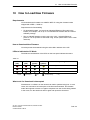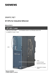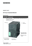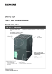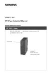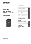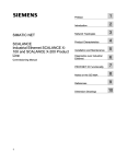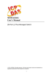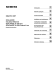
1
SIMATIC NET
S7-CPs for Industrial Ethernet
Manual Part B3L
CP 343-1 Lean
6GK7 343−1CX10−0XE0
as of hardware version 2, as of firmware version V2.0
for SIMATIC S7−300 / C7−300
LED displays
TP port:
2 x 8−pin RJ−45 socket
(beneath the front panel)
X = Placeholder for hardware
version
Release 03/2007
C79000-G8976-C198-04
Notes on the Product
Notes on the Product
Product Names
This description contains information on the following product
S
CP 343−1 Lean
Order number 6GK7 343−1CX10−0XE0
as of hardware version 2 and firmware version V2.0
for SIMATIC S7−300 / C7−300
Note
In this document, the term CP is used instead of the full product name.
Printed Product Information Supplied with the Product
Note
All the notices in the Product Information Bulletin shipped with this device must
be adhered to.
Compatibility with the Previous Version
Note
Due to the increased functionality and restrictions, pay particular attention to
the notes in Chapter 8 of this manual.
Address label: Unique MAC address preset for the CP
The CP ships with a factory-set MAC address.
To ensure a unique address assignment, we recommend that you use this factory
set MAC address when configuring the module!
-
B3L−2
CP 343-1 Lean for Industrial Ethernet / Manual Part B3L
Release 03/2007
C79000-G8976-C198-04
Contents
Contents
Contents − Part A
Ethernet CPs − General information . . . . . . . . . . . . . . . . . . .
see general part
Note
Please remember that Part A of the device manual also belongs to the description
of the CP. Among other things, it contains explanations of the safety notices and
general information that applies to all S7 CPs for Industrial Ethernet.
You will find the references in this Part B of the manual /.../ in the Appendix of the
general Part A of the manual.
The following version of the manual Part A of the manual belongs to this version of
Part B: Release 01/2007
You can download the general Part from the Internet:
http://www4.ad.siemens.de/view/cs/en/8777865
Contents − Part B3L
1
Properties / Services . . . . . . . . . . . . . . . . . . . . . . . . . . . . . . . . . . . . . . . . . . . . . . . . . . .
B3L−5
2
Requirements for Use . . . . . . . . . . . . . . . . . . . . . . . . . . . . . . . . . . . . . . . . . . . . . . . . . .
B3L−8
3
Installation and Commissioning . . . . . . . . . . . . . . . . . . . . . . . . . . . . . . . . . . . . . . . . .
B3L−11
3.1
Procedure / Steps . . . . . . . . . . . . . . . . . . . . . . . . . . . . . . . . . . . . . . . . . . . .
B3L−11
4
Displays . . . . . . . . . . . . . . . . . . . . . . . . . . . . . . . . . . . . . . . . . . . . . . . . . . . . . . . . . . . . . . .
B3L−14
5
Performance Data . . . . . . . . . . . . . . . . . . . . . . . . . . . . . . . . . . . . . . . . . . . . . . . . . . . . . .
B3L−17
6
5.1
Number of Possible Connections over Ethernet . . . . . . . . . . . . . . . . . . .
B3L−17
5.2
Characteristic Data for S7 Communication . . . . . . . . . . . . . . . . . . . . . . .
B3L−17
5.3
Characteristics of the SEND/RECEIVE Interface . . . . . . . . . . . . . . . . .
B3L−18
5.4
Characteristic Data for PROFINET IO . . . . . . . . . . . . . . . . . . . . . . . . . . .
B3L−19
Configuring and Programming the CP as a PROFINET IO Device . . . . . . . . . .
B3L−20
6.1
Overview of the Preparatory Steps . . . . . . . . . . . . . . . . . . . . . . . . . . . . .
B3L−20
6.2
Principle of Data Exchange over PROFINET IO . . . . . . . . . . . . . . . . . .
B3L−21
6.3
6.3.1
6.3.2
Configuration . . . . . . . . . . . . . . . . . . . . . . . . . . . . . . . . . . . . . . . . . . . . . . . .
Installing the CP and Specifying it as PROFINET IO Device . . . . . . . .
Assigning the PROFINET IO Device to a PROFINET IO Controller . .
B3L−22
B3L−22
B3L−24
6.4
6.4.1
Programming . . . . . . . . . . . . . . . . . . . . . . . . . . . . . . . . . . . . . . . . . . . . . . . .
Interface for Programming on the PROFINET IO Device . . . . . . . . . . .
B3L−27
B3L−27
CP 343-1 Lean for Industrial Ethernet / Manual Part B3L
Release 03/2007
C79000-G8976-C198-04
B3L−3
Contents
7
8
9
6.4.2
Initialization and Configuration . . . . . . . . . . . . . . . . . . . . . . . . . . . . . . . . .
B3L−28
6.5
Example of Configuration and Programming . . . . . . . . . . . . . . . . . . . . .
B3L−30
Web Diagnostics . . . . . . . . . . . . . . . . . . . . . . . . . . . . . . . . . . . . . . . . . . . . . . . . . . . . . . .
B3L−33
7.1
Requirements and Use . . . . . . . . . . . . . . . . . . . . . . . . . . . . . . . . . . . . . . . .
B3L−33
7.2
7.2.1
7.2.2
7.2.3
7.2.4
7.2.5
7.2.6
Diagnostics Pages of the CP . . . . . . . . . . . . . . . . . . . . . . . . . . . . . . . . . . .
Start Page . . . . . . . . . . . . . . . . . . . . . . . . . . . . . . . . . . . . . . . . . . . . . . . . . . .
Identification . . . . . . . . . . . . . . . . . . . . . . . . . . . . . . . . . . . . . . . . . . . . . . . . .
Rack Configuration . . . . . . . . . . . . . . . . . . . . . . . . . . . . . . . . . . . . . . . . . . .
Diagnostic Buffer . . . . . . . . . . . . . . . . . . . . . . . . . . . . . . . . . . . . . . . . . . . . .
Industrial Ethernet . . . . . . . . . . . . . . . . . . . . . . . . . . . . . . . . . . . . . . . . . . . .
PROFINET IO . . . . . . . . . . . . . . . . . . . . . . . . . . . . . . . . . . . . . . . . . . . . . . .
B3L−34
B3L−35
B3L−36
B3L−37
B3L−39
B3L−40
B3L−42
Compatibility with Predecessor Products . . . . . . . . . . . . . . . . . . . . . . . . . . . . . . . .
B3L−44
8.1
Extended Functionality . . . . . . . . . . . . . . . . . . . . . . . . . . . . . . . . . . . . . . . .
B3L−44
8.2
Replacing Older Modules / Replacing Faulty Modules . . . . . . . . . . . . .
B3L−44
Further Notes on Operation . . . . . . . . . . . . . . . . . . . . . . . . . . . . . . . . . . . . . . . . . . . . .
B3L−46
9.1
Memory Reset . . . . . . . . . . . . . . . . . . . . . . . . . . . . . . . . . . . . . . . . . . . . . . .
B3L−46
9.2
Working with Fast Ethernet − automatic switchover . . . . . . . . . . . . . . .
B3L−47
9.3
SNMP Agent . . . . . . . . . . . . . . . . . . . . . . . . . . . . . . . . . . . . . . . . . . . . . . . .
B3L−49
9.4
Possible Security Gaps on Standard IT Interfaces / Preventing
Illegal Access . . . . . . . . . . . . . . . . . . . . . . . . . . . . . . . . . . . . . . . . . . . . . . . .
B3L−50
9.5
Influence of MPI on Connections via Industrial Ethernet . . . . . . . . . . .
B3L−50
9.6
Special Features of IP Configuration . . . . . . . . . . . . . . . . . . . . . . . . . . . .
B3L−51
9.7
Reserved Port Numbers . . . . . . . . . . . . . . . . . . . . . . . . . . . . . . . . . . . . . . .
B3L−51
9.8
Restart after Detection of a Duplicate IP Address in the Network . . . .
B3L−52
9.9
Obtaining the IP Address over DHCP − CP STOP on Expiry of
the Lease . . . . . . . . . . . . . . . . . . . . . . . . . . . . . . . . . . . . . . . . . . . . . . . . . . .
B3L−52
9.10
Other information available about the CP . . . . . . . . . . . . . . . . . . . . . . . .
B3L−52
10 How to Load New Firmware . . . . . . . . . . . . . . . . . . . . . . . . . . . . . . . . . . . . . . . . . . . .
B3L−53
11
B3L−54
Technical Specifications . . . . . . . . . . . . . . . . . . . . . . . . . . . . . . . . . . . . . . . . . . . . . . .
B3L−4
CP 343-1 Lean for Industrial Ethernet / Manual Part B3L
Release 03/2007
C79000-G8976-C198-04
1
1
Properties / Services
Properties / Services
Application
The CP 343−1 Lean communications processor is designed for operation in a
SIMATIC S7-300 programmable logic controller. It allows attachment of the
S7−300 to Industrial Ethernet and supports PROFINET IO.
A 2-port switch with autocrossing, autonegotiation and autosensing was integrated
in the CP for simple integration in a line or for attaching a further Ethernet device.
Services
The CP supports the following communication services:
S
PROFINET IO device
Integration of the SIMATIC S7−300 programmable controller over the CP as
intelligent PROFINET IO device.
S
S7 communication and PG/OP communication
− PG functions (including routing)
− Operator control and monitoring functions (HMI)
− Server for data exchange on S7 connections configured at one end only
without communication blocks on the S7-300 / C7-300 station
S
S5 compatible communication with
− SEND/RECEIVE interface over ISO-on-TCP, TCP and UDP connections
− Multicast over UDP connection
The multicast mode is made possible by selecting a suitable IP address
when configuring connections.
− FETCH/WRITE services (server; corresponding to S5 protocol) via
ISO-on-TCP connections and TCP connections;
The addressing mode can be configured for FETCH/WRITE access as the
S7 or S5 addressing mode.
− LOCK/UNLOCK with FETCH/WRITE services;
CP 343-1 Lean for Industrial Ethernet / Manual Part B3L
Release 03/2007
C79000-G8976-C198-04
B3L−5
1
Properties / Services
S
Time-of-day synchronization over Industrial Ethernet using the following
configurable modes:
− SIMATIC mode
The CP receives MMS time frames and synchronizes its local time and the
time of the CPU (accuracy approx. +/− 1 second);
or
− NTP mode (NTP: Network Time Protocol)
The CP sends time-of-day queries at regular intervals to an NTP server and
synchronizes its local time of day and the time of the CPU (accuracy approx.
+/− 1 second).
S
Time of day for the diagnostic buffer
If a time master exists (using the NTP or SIMATIC mode), the time for the
CP-internal diagnostic buffer is synchronized over the LAN (accuracy approx.
+/− 10 ms)
S
Addressing using a factory-set MAC address
The CP can be reached over the default MAC address to allow an IP address to
be assigned.
S
SNMP Agent
The CP supports data queries over SNMP in version V1 (Simple Network
Management Protocol) according to the MIB II and LLDP MIB standard.
You will find more information on MIB in the manual “Commissioning PC
Stations” on the SIMATIC NET Manual Collection or at the following
SIMATIC NET Internet page:
http://support.automation.siemens.com/WW/view/en/15177711
S
IP configuration
You can configure how and with which method the CP is assigned the IP
address, the subnet mask and the address of a default router.
It is also possible, as an alternative, to assign the connection configuration to
the CP using STEP 7 or using a block interface in the user program (FB55:
IP_CONFIG) (see /Part A/).
S
Web diagnostics
With the aid of Web diagnostics, you can read out the diagnostic data from a
station connected over the CP to a PG/PC with an Internet browser.
B3L−6
CP 343-1 Lean for Industrial Ethernet / Manual Part B3L
Release 03/2007
C79000-G8976-C198-04
1
Properties / Services
Configuration
It is possible to download the configuration data to the CP over MPI or
LAN/Industrial Ethernet. You require STEP 7 with NCM S7 for Industrial Ethernet
(NCM IE) with the following version:
Table 1-1
Version STEP 7 / NCM IE
Functions of the CP
V5.2 or higher
The range of functions of the CP 343−1 Lean (CX00) can be
configured.
V5.4 or higher
Requirement for configuring the full functionality of the
CP 343−1 Lean (CX10 with firmware V1.0) including PROFINET
IO.
V5.4 Service Pack 2 *)
Requirement for configuring the full functionality of the
CP 343−1 Lean (CX10 with firmware V2.0) including Web
diagnostics.
*)
To use the CP with V5.4 Service Pack 1, you will need to install Hotfix 2, the corresponding hardware
update and a block setup. You will find more information at the following Internet page:
http://www4.ad.siemens.de/WW/news/en/24463868
Programming − Using Blocks
For some communications services, there are pre-programmed blocks (FCs/FBs)
available as the interface in your STEP 7 user program.
You will find a detailed description of these blocks in the NCM S7 for Ethernet
manuals.
Notice
We recommend that you always use the latest block versions for all module types.
You will find information on the latest block version and links to download the
current blocks in our Customer Support area on the Internet:
http://www4.ad.siemens.de/WW/news/en/8797900
If you are using older block types, this recommendation only applies if you also
have the latest firmware version.
You will find further information and Internet addresses in the Preface of the
General Part of this manual.
CP 343-1 Lean for Industrial Ethernet / Manual Part B3L
Release 03/2007
C79000-G8976-C198-04
B3L−7
2
2
Requirements for Use
Requirements for Use
General Operation
The CP can be operated in the following device families:
S
S7−300 stations with the CPU types
− Standard
− Compact
− Modular
S
C7 control systems in C7 packaging system
The following tables show the devices with which the CP can be operated with this
range of functions:
Notice
The tables list the CPUs and devices approved at the time of printing this manual.
S7-300 CPUs or C7 or C7 control systems approved later and not listed in the
table also support the range of functions described here.
Table 2-1
Use of the CP with S7−300
CPU
B3L−8
Order Number
CPU 312
6ES7 312−1AD10−0AB0
6ES7 312−1AE13−0AB0
CPU 312C
6ES7 312−5BD01−0AB0
6ES7 312−5BE03−0AB0
CPU 312 IFM
6ES7 312−5AC02−0AB0
CPU 313
6ES7 313−1AD03−0AB0
CPU 313C
6ES7 313−5BE00−0AB0
6ES7 313−5BE01−0AB0
6ES7 313−5BF03−0AB0
CPU 313C−2 DP
6ES7 313−6CE00−0AB0
6ES7 313−6CE01−0AB0
6ES7 313−6CF03−0AB0
CPU 313C−2 PtP
6ES7 313−6BE00−0AB0
6ES7 313−6BE01−0AB0
6ES7 313−6BF03−0AB0
CPU 314
6ES7 314−6AE01−0AB0
6ES7 314−6AE02−0AB0
6ES7 314−6AE03−0AB0
6ES7 314−6AE04−0AB0
6ES7 314−1AF10−0AB0
6ES7 314−1AF11−0AB0
6ES7 314−1AG13−0AB0
CP 343-1 Lean for Industrial Ethernet / Manual Part B3L
Release 03/2007
C79000-G8976-C198-04
2
Table 2-1
Requirements for Use
Use of the CP with S7−300
CPU
Order Number
CPU 314 IFM
6ES7 314−5AE03−0AB0
6ES7 314−5AE10−0AB0
CPU 314C−2 DP
6ES7 314−6CF00−0AB0
6ES7 314−6CF02−0AB0
6ES7 314−6CG03−0AB0
CPU 314C−2 PtP
6ES7 314−6BF00−0AB0
6ES7 314−6BF01−0AB0
6ES7 314−6BF02−0AB0
6ES7 314−6BG03−0AB0
CPU 315
6ES7 315−1AF03−0AB0
CPU 315−2 DP
6ES7 315−2AF03−0AB0
6ES7 315−2AG10−0AB0
CPU 315−2 PN/DP
6ES7 315−2EG10−0AB0
6ES7 315−2EH13−0AB0
CPU 315F−2 DP
6ES7 315−6FF01−0AB0
CPU 315F−2 PN/DP
6ES7 315−2FH10−0AB0
6ES7 315−2FH13−0AB0
CPU 316
6ES7 316−1AG00−0AB0
CPU 316−2 DP
6ES7 316−2AG00−0AB0
CPU 317−2 DP
6ES7 317−2AJ10−0AB0
CPU 317−2 PN/DP
6ES7 317−2EJ10−0AB0
6ES7 317−2EK13−0AB0
CPU 317F−2 DP
6ES7 317−6FF00−0AB0
6ES7 317−6FF03−0AB0
CPU 317F−2 PN/DP
6ES7 317−2FJ10−0AB0
6ES7 317−2FK13−0AB0
CPU 318−2
6ES7 318−2AJ00−0AB0
CPU 319−3 PN/DP
6ES7 318−3EL00−0AB0
CPU 614
6ES7 614−1AH03−0AB3
CP 343-1 Lean for Industrial Ethernet / Manual Part B3L
Release 03/2007
C79000-G8976-C198-04
B3L−9
2
Requirements for Use
Table 2-2
Use of the CP in C7 Control Systems
C7
B3L−10
Order Number
C7−613
6ES7 613−1CA01−0AE03
6ES7 613−1CA02−0AE3
C7−633 DP
6ES7 633−2BF02−0AE03
C7−635 Keys
6ES7 635−2EC01−0AE3
6ES7 635−2EC02−0AE3
C7−635 Touch
6ES7 635−2EB01−0AE03
6ES7 635−2EB02−0AE3
C7−636 Keys
6ES7 636−2EC00−0AE03
6ES7 636−2EC00−0AE3
C7−636 Touch
6ES7 636−2EB00−0AE3
CP 343-1 Lean for Industrial Ethernet / Manual Part B3L
Release 03/2007
C79000-G8976-C198-04
3
3
Installation and Commissioning
Installation and Commissioning
3.1
Procedure / Steps
Step
1. Install the CP on the S7 standard rail.
2. Establish the connection via the enclosed bus
connector to the backplane bus.
Explanation / Meaning
Slots 4 to 11 are permitted for the CP in racks 0 to 3
(connected by IM 360/361).
Proceed as in the sections dealing with setup and
wiring, described in detail in /1/.
Note
The CP cannot be used in an extension rack that is connected via the IM 365! Reason: The required
communication bus is not connected to the extension rack via the IM 365.
3. Connect the CP to the power supply.
Follow the steps as described in detail in /1/ when
wiring between the power supply and the CPU.
Notes
S The CPU, CP and IM (if one exists) must be connected to the same power supply.
S Only wire up the S7-300 / C7-300 with the power switched off!
4. Attach the CP to Industrial Ethernet.
5. The remaining steps in commissioning involve
downloading the configuration data.
To download the configuration, you can connect
the PG as follows:
S via MPI
S via Industrial Ethernet
For further details, refer to the general Part A of
this manual:
− addressing the first time (IP address
assignment / node initialization);
− downloading the defined configuration
The PG/PC requires a LAN attachment, for
example via a CP 1613 or CP 1411 and must have
the necessary software (for example the S7-1613
package or SOFTNET IE). The TCP/IP protocol
must be installed. The protocol used must then be
applied to the S7ONLINE access point.
6. User diagnostics for commissioning and to
analyze problems.
The following options are available:
S The LED displays on the CP
S Hardware diagnostics and troubleshooting with
STEP 7
S Communication diagnostics with STEP 7 / NCM
Diagnostics
S Standard information using HW Config
S Web diagnostics
S If applicable, evaluation of the alarm block
FB54 in the user program
CP 343-1 Lean for Industrial Ethernet / Manual Part B3L
Release 03/2007
C79000-G8976-C198-04
B3L−11
3
Installation and Commissioning
Attachment to Industrial
Ethernet:
Slider for setting
the chassis
ground contact
Figure 3-1
2 x 8-pin RJ-45 jack
Connectors of a CP 343−1 Lean with the Front Panel Open
Ground/Chassis Ground Concept
Notice
Please note the instructions regarding the grounding and chassis ground concept
in the SIMATIC S7 installation guides; see “SIMATIC S7 Programmable Controller
S7−300 − Installation and Hardware: Installation Manual” /1/.
Behind the hinged panel on the left of the device, you will see a slider with which
you can connect or disconnect the chassis ground of the 24 V power supply with
reference ground.
S
Slider pushed in: chassis and reference ground connected (note: the slider
must be felt to lock in place).
S
Slider pulled out: No connection between chassis and reference ground.
When shipped: Slider pushed in
Use a screwdriver to set the slider.
Note
An Ethernet cable can also be inserted and removed with the power supply on.
B3L−12
CP 343-1 Lean for Industrial Ethernet / Manual Part B3L
Release 03/2007
C79000-G8976-C198-04
3
Installation and Commissioning
Note
The hinged front panel must be kept closed during operation.
The module must be installed so that its upper and lower ventilation slits are not
covered, allowing adequate ventilation.
!
Warning
When used under hazardous conditions (zone 2), the devices must be installed in
an enclosure.
To comply with ATEX100a (EN 60079−15), this enclosure must meet the
requirements of at least IP54 in compliance with EN 60529.
WARNING − EXPLOSION HAZARD: DO NOT DISCONNECT EQUIPMENT
WHEN A FLAMMABLE OR COMBUSTIBLE ATMOSPHERE IS PRESENT.
!
Warning
The device is designed for operation with safety extra-low voltage (SELV). This
means that only safety extra-low voltages (SELV) complying with
IEC950/EN60950/ VDE0805 may be connected to the power supply terminals.
The power unit for supplying the device must comply with NEC Class 2 as
described by the National Electrical Code(r) (ANSI/NFPA 70).
The power of all connected power units in total must correspond to a limited power
source (LPS).
CP 343-1 Lean for Industrial Ethernet / Manual Part B3L
Release 03/2007
C79000-G8976-C198-04
B3L−13
4
4
Displays
Displays
The display on the front panel consists of 8 LEDs that indicate the operating mode
and the communication status.
Front panel:
SF
BF
DC5V
RX/TX
RUN
STOP
P1
P2
The LEDs have the following meaning:
B3L−14
S
SF:
Group error
S
BF:
Bus fault PROFINET IO
S
DCV5:
DC 5 V power supply via the backplane bus (green = OK)
S
RX/TX: Acyclic data exchange, for example Send/Receive
(not relevant for PROFINET IO data)
S
RUN:
S
STOP: STOP mode
S
P1 / P2: Link status of Ethernet port 1 / port 2
RUN mode
CP 343-1 Lean for Industrial Ethernet / Manual Part B3L
Release 03/2007
C79000-G8976-C198-04
4
Displays
LEDs for displaying the mode
The different combinations of the LEDs on the front panel indicate the status:
SF(red)
BF (red)
RUN
(green)
STOP
(yellow)
CP Operating Mode
S Starting up after power “ON”
or
S Stopped (STOP) with errors
−
In this state, the CPU or intelligent
modules in the rack remain accessible
using PG functions.
Starting up (STOP->RUN)
Running (RUN)
Stopping (RUN->STOP)
Stopped (STOP)
In the STOP mode configuring and performing
diagnostics on the CP remain possible.
−
−
−
S No LAN cable plugged in
or
S Duplicate IP address detected
−
−
−
The CP is configured as a PROFINET IO
device; there is no data exchange with the
PROFINET IO controller
Module fault / system error
Downloading firmware.
Firmware was successfully downloaded.
Firmware could not be downloaded.
Legend:
(colored) on
off
CP 343-1 Lean for Industrial Ethernet / Manual Part B3L
Release 03/2007
C79000-G8976-C198-04
(colored) flashing
“−” any
B3L−15
4
Displays
LEDs for displaying the CP communication status
In addition to the LEDs that signal the CP state, the following LEDs provide
information about the status of the CP interface to Industrial Ethernet.
Table 4-1
Display
LED
Meaning
The CP is sending/receiving over Industrial
Ethernet
RX/TX (green)
Note:
Sending / receiving over PROFINET IO is
not signaled here.
Port has no connection to
Industrial Ethernet.
P1 / P2
(green / yellow)
green
Existing connection over port to
Industrial Ethernet (LINK status).
green /
yellow
LED flashes yellow (constant light green):
Port sending/receiving over
Industrial Ethernet or PROFINET IO.
Note:
All received / sent frames are signaled for
each specific port including those simply
forwarded by the switch.
yellow
P1 / P2
(green / yellow)
Legend:
B3L−16
(colored) on
off
Continuous data transfer at the port over
Industrial Ethernet (for example
PROFINET IO).
(colored) flashing
“−” any
CP 343-1 Lean for Industrial Ethernet / Manual Part B3L
Release 03/2007
C79000-G8976-C198-04
5
5
Performance Data
Performance Data
5.1
Number of Possible Connections over Ethernet
Table 5-1
Characteristic
Explanation / Values
Permitted number of simultaneous connections in
total over Industrial Ethernet
12 maximum
Example of Maximum Load
You can operate:
4 S7 connections
4 ISO-on-TCP connections
2 TCP connections
2 UDP connections
Also:
5.2
S
Further TCP connections for Web diagnostics
S
1 PROFINET connection to a PROFINET IO controller
Characteristic Data for S7 Communication
Table 5-2
Characteristic
Explanation / Values
Number of connections for S7 communication on
Industrial Ethernet for
4 maximum
(the number depends on the CPU type being used.
S Operator control and monitoring functions (HMI) Please refer to /1/ for the values for your CPU.)
S S7 connections configured at one end
LAN interface − data record length per protocol unit
S sending
S receiving
CP 343-1 Lean for Industrial Ethernet / Manual Part B3L
Release 03/2007
C79000-G8976-C198-04
240 bytes / PDU
240 bytes / PDU
B3L−17
5
Performance Data
5.3
Characteristics of the SEND/RECEIVE Interface
Table 5-3
Characteristic
Explanation / Values
Number of ISO-on-TCP connections + TCP
connections + UDP connections in total
8 maximum
Notes:
S All UDP connections are also possible in the
multicast mode
S Free UDP connections are supported by the
CP.
Max. data length for blocks AG_SEND (V4.0 and
higher) and AG_RECV (V4.0 and higher)
AG_SEND and AG_RECV allow the transfer of
data fields of between 1 and 240 bytes.
S 1 to 8192 bytes for ISO-on-TCP, TCP;
S 1 to 2048 bytes for UDP
Restrictions for UDP
S Transfer is not confirmed
The transmission of UDP frames is unconfirmed, in
other words the loss of messages is not detected
or displayed by the send blocks (AG_SEND).
S Data field length
The maximum length of the data fields is 2048
bytes.
S No reception of UDP broadcast
To avoid communication overload resulting from a
high broadcast load, the CP does not permit
reception of UDP broadcast.
Execution Times of the FCs AG_SEND / AG_RECV
To calculate the CPU cycle times (OB1) with SEND/RECEIVE connections, the
execution time for the FCs (FC AG_SEND, FC AG_RECV) required for processing
on the S7−300 / C7−300 CPU is the decisive factor.
Table 5-4
Component
Explanation / Values
Execution time on the CPU
315−2 DP
(6ES7 315−2EG10−0AB0)
per AG_SEND block call:
per AG_RECV block call:
S <1 ms at <= 240 bytes
S <1 ms at <= 240 bytes
Execution time on the CPU
317−2 PN/DP
(6ES7 317−2EJ10−0AB0)
per AG_SEND block call:
per AG_RECV block call:
S <0.8 ms at <= 240 bytes
S <0.8 ms at <= 240 bytes
B3L−18
CP 343-1 Lean for Industrial Ethernet / Manual Part B3L
Release 03/2007
C79000-G8976-C198-04
5
5.4
Performance Data
Characteristic Data for PROFINET IO
CP as PROFINET IO device
The CP supports the following maximum configuration as a PROFINET IO device:
Table 5-5
Explanation / Values
Characteristic
Size of the input area of the PROFINET IO device
512 bytes max.
Size of the output area of the PROFINET IO device
512 bytes max.
Size of the IO data area per submodule in a PROFINET IO device
S Inputs
S Outputs
240 bytes
Size of the consistency area for a submodule
240 bytes
240 bytes
Maximum number of submodules
32
Execution times of the FCs PNIO_SEND / PNIO_RECV
The calculation of the reaction times with PROFINET IO is determined by the
execution time of the function blocks required on the S7-300 CPU (PNIO_SEND,
PNIO_RECV).
Table 5-6
Explanation / Values
Component
Execution time on the CPU
315−2DP
(6ES7 315−2EG10−0AB0)
per PNIO_SEND block call:
per PNIO_RECV block call:
S < 1 ms at 240 bytes
S < 1 ms at 240 bytes
Execution time on the CPU
317−2PN/DP
(6ES7 317−2EJ10−0AB0)
per PNIO_SEND block call:
per PNIO_RECV block call:
S < 0.8 ms at 240 bytes
S < 0.8 ms at 240 bytes
CP 343-1 Lean for Industrial Ethernet / Manual Part B3L
Release 03/2007
C79000-G8976-C198-04
B3L−19
6
Configuring and Programming the CP as a PROFINET IO Device
6
Configuring and Programming the CP as a
PROFINET IO Device
“Intelligent” PROFINET IO Device
A CP 343−1 Lean can be configured so that the SIMATIC 300 station can be
addressed as a PROFINET IO device. Due to the programmability of SIMATIC 300
stations, they are also known as “intelligent” PROFINET IO devices because:
Process data can be processed before it is forwarded to the PROFINET IO
controller or after it has been received from it and output to the process I/O.
In the following sections, the name “PROFINET IO device” also refers to the CP
located in the S7 station and configured as a PROFINET IO device.
6.1
Overview of the Preparatory Steps
The following steps are necessary to operate the SIMATIC 300 station with the
CP as a PROFINET IO device:
Configuration
Programming
Configure the CP as PROFINET IO device for
data exchange over PROFINET IO. See Section
6.3
Write the user program for the PROFINET IO
device SIMATIC S7 and download it to the
SIMATIC S7 CPU. See Section 6.4
Commissioning
Commission and test the PROFINET
IO controller and PROFINET IO
device
Communication diagnostics (for example
if problems occur during communication)
B3L−20
CP 343-1 Lean for Industrial Ethernet / Manual Part B3L
Release 03/2007
C79000-G8976-C198-04
6
6.2
Configuring and Programming the CP as a PROFINET IO Device
Principle of Data Exchange over PROFINET IO
Data Exchange between controller and CP as PROFINET IO device
Data exchange between a PROFINET IO controller and PROFINET IO device
involves the following procedure:
S
On the PROFINET IO controller
Data exchange is initiated by the PROFINET IO controller that writes output
data to the configured output area (O addresses) and fetches input data from
the configured input area (I addresses).
S
On the PROFINET IO device
Data is processed by the CP in the PROFINET IO device on the interface to the
PROFINET IO controller.
Communication within the PROFINET IO device involves calling the FCs
PNIO_RECV and PNIO_SEND in the user program of the CPU.
PROFINET IO device
CPU
STEP 7
user program
Process
outputs
PROFINET
IO controller
CP
CP
database
PROFINET IO
data areas (DB,
bit memory)
PNIO_RECV
PNIO_SEND
PROFINET IO
Receive
Send
Configured
O addresses
Configured
I addresses
Process
inputs
Figure 6-1
Interaction between PROFINET IO Device and PROFINET IO controller
Note
In the CPU of the device, the IO data areas for input data and output data are
transferred as an entire area to or from one of the data areas (DB, bit memory)
including any gaps.
CP 343-1 Lean for Industrial Ethernet / Manual Part B3L
Release 03/2007
C79000-G8976-C198-04
B3L−21
6
Configuring and Programming the CP as a PROFINET IO Device
6.3
Configuration
Configuring the CP as a PROFINET IO device involves the two following activities
in STEP 7:
1. The CP is inserted in a SIMATIC 300 station in HW Config and enabled for
PROFINET IO device mode in the properties dialog.
2. The CP is assigned to a PROFINET IO controller as a PROFINET IO device in
HW Config.
Notice
These two configuration steps can be taken independently in HW Config. In both
steps, make sure that the configured device name for the PROFINET IO device
matches exactly.
6.3.1
Installing the CP and Specifying it as PROFINET IO Device
Follow the steps below in STEP 7 / HW Config:
1. Take the required CP from the hardware catalog and insert the module in the
SIMATIC 300 station.
Figure 6-2
B3L−22
Inserting the CP in a SIMATIC Station in HW Config
CP 343-1 Lean for Industrial Ethernet / Manual Part B3L
Release 03/2007
C79000-G8976-C198-04
6
Configuring and Programming the CP as a PROFINET IO Device
2. Check and, if necessary, correct the IP address in the “Properties Ethernet”
dialog.
Notice
The IP address of the PROFINET IO device and the IP address of the
PROFINET IO controller must be located in the same IP subnet.
3. Complete the “Properties Ethernet” dialog with OK.
4. Open the properties dialog of the CP.
5. Assign a unique name to the CP as PROFINET node in the “PROFINET” tab.
This name may only be assigned once in the PROFINET IO line.
6. Select the option “Enable PROFINET IO device operation”.
Figure 6-3
Setting the Device Name and the PROFINET IO Device Mode
7. Download the configuration data to the SIMATIC 300 station.
CP 343-1 Lean for Industrial Ethernet / Manual Part B3L
Release 03/2007
C79000-G8976-C198-04
B3L−23
6
Configuring and Programming the CP as a PROFINET IO Device
6.3.2
Assigning the PROFINET IO Device to a PROFINET IO
Controller
PROFINET IO Controller
This section describes the configuration of PROFINET IO controllers with STEP 7.
This includes:
S
Stations of the type SIMATIC 300 and SIMATIC 400
− CPU with integrated PROFINET IO controller (for example CPU 317−2
PN/DP).
− CPU with external PROFINET IO controller (for example CP 343−1).
S
SIMATIC PC station
− For example with CP 1616
If you do not configure your system with STEP 7, you will need to use the GSDML
file of the CP to configure the CP in your configuration system (download address
see Section 9.10)
When configuring the PROFINET IO device (see Section 6.3.1), the selected
PROFINET IO controller is unimportant.
Requirements for Configuration in STEP 7
There must be a SIMATIC station in the STEP 7 project in which a module (CPU
or CP) supports operation as PROFINET IO controller.
Notice
The IP address of the PROFINET IO device and the IP address of the PROFINET
IO controller must be located in the same IP subnet.
Step 1: Configuring the PROFINET IO controller
With some PROFINET IO controller types, STEP 7 automatically creates a
PROFINET IO system as soon as you insert the module, otherwise you may need
to add a PROFINET IO system. Drag the required IO devices from the hardware
catalog to this PROFINET IO system.
Configure a PROFINET IO controller as follows:
1. Open the hardware configuration of the station you want as PROFINET IO
controller in HW Config.
2. If no PROFINET IO system exists, select the PROFINET IO controller (for
example CP 343−1 EX30/GX21, CP 443−1 EX41, CPU 317−2 PN/DP) and
insert a PROFINET IO system (menu “Insert” "“PROFINET IO System”).
B3L−24
CP 343-1 Lean for Industrial Ethernet / Manual Part B3L
Release 03/2007
C79000-G8976-C198-04
6
Configuring and Programming the CP as a PROFINET IO Device
Result:
You will see the connector symbol for the PROFINET IO system beside the
PROFINET IO controller.
Step 2: Configuring the PROFINET IO device on the PROFINET IO controller
1. Open the hardware catalog and select a version of the CP V2.0 or higher as the
PROFINET IO device from the folder “PROFINET IO” "“I/O”
"“SIMATIC S7−CP” "“CP 343−1 Lean”.
2. Connect the CP with the PROFINET IO system (drag and drop).
3. Add input and output modules with the required I/O data length (1 to max. 240
bytes) to the PROFINET IO device.
The following screenshot shows the configuration table of the PROFINET IO
controller with an S7−400 station as PROFINET IO controller. The PROFINET IO
device shown here, for example, has three modules for process inputs (I address)
and process outputs (O address).
Figure 6-4
SIMATIC Station with PROFINET IO System with the CP as Device with Input (DI) and
Output Modules (DO)
CP 343-1 Lean for Industrial Ethernet / Manual Part B3L
Release 03/2007
C79000-G8976-C198-04
B3L−25
6
Configuring and Programming the CP as a PROFINET IO Device
Step 3: Configuring the properties of the CP as PROFINET IO device
Continue configuration in HW Config as follows:
1. Open the properties dialog of the PROFINET IO device that you inserted in the
PROFINET IO system.
2. In the “General” tab, assign the same device name that you selected in Section
6.3.1.
Figure 6-5
Properties Dialog of the Device: Assigning the Device Name
3. Deselect the “Assign IP address by IO controller” option.
This step is a recommendation!
By deactivating this option, the IP address you assigned when you installed the
CP in the SIMATIC 300 station (see Section 6.3.1) comes into effect on the
PROFINET IO device. Otherwise the IP address you selected there will be
overwritten by an IP address assigned by the PROFINET IO controller. If it is
overwritten, any configured connections (S7, ISO-on-TCP, TCP) will no longer
be established.
B3L−26
CP 343-1 Lean for Industrial Ethernet / Manual Part B3L
Release 03/2007
C79000-G8976-C198-04
6
Configuring and Programming the CP as a PROFINET IO Device
No further parameter assignment of the modules is necessary.
Note
By selecting suitable network components and setting the network properties
(Section 9.2) make sure that in PROFINET IO mode, the PROFINET line can be
operated without exception at 100 Mbps full duplex.
6.4
Programming
By programming, you specify the sequence of the user program for the CPU and
therefore also access to the I/O data.
To write and read process data, use the FCs PNIO_SEND (FC11) or PNIO_RECV
(FC12) from the SIMATIC NET block library in your user program.
How to use the existing functions (FCs) in your user program for PROFINET IO
device mode is described in the following sections of this chapter.
You will find an example matching the configuration described in the previous
chapter in Section 6.5.
6.4.1
Interface for Programming on the PROFINET IO Device
FCs
Two functions (FCs) are available for data exchange using the STEP 7 user
program:
S
PNIO_SEND (FC11)
This FC reads the preprocessed process inputs of the CPU and transfers them
to the PROFINET IO controller (configured I addresses).
The preprocessed process inputs are available in a DB or bit memory area.
S
PNIO_RECV (FC12)
The block accepts the data transferred by the PROFINET IO controller
(configured O addresses) and writes it to the data areas of the CPU reserved
for process outputs.
You will find the precise syntax of the FCs and the meaning of the block
parameters in the chapter on FCs in the general part of the manual or in the online
help for the block library in STEP 7.
CP 343-1 Lean for Industrial Ethernet / Manual Part B3L
Release 03/2007
C79000-G8976-C198-04
B3L−27
6
Configuring and Programming the CP as a PROFINET IO Device
Data consistency
The length information in the block call must be identical to the total length of the
input or output data configured for this PROFINET IO device.
The entire input or output data area of the PROFINET IO controller is transferred
in its entirety between the CP and CPU and is therefore consistent.
Note: Remember, however, that in terms of the “IO user data” within a PROFINET
IO system, only the data consistency of individual IO slots can be guaranteed. This
applies regardless of whether consistent data transfer between the CPU and CP is
guaranteed for the blocks described here.
6.4.2
Initialization and Configuration
Initialization
As a PROFINET IO device, the CP requires the following information in the user
program for configuration by the PROFINET IO controller at every startup:
S
Length of the input data (when FC11 is called)
S
Length of the output data (when FC12 is called)
When the connection is established between the PROFINET IO controller and the
PROFINET IO devices of a PROFINET IO line, the entire length of the input and
output data is checked. The PROFINET IO controller compares the configured
entire length of the input and output data with the LEN parameter of FC11 and
FC12 in the user program of the device for every PROFINET IO device.
If the length information for the input and output data does not match, the block is
terminated with an error.
During this initialization phase, the two blocks must be called until FC11 signals
DONE=1 and FC12 signals NDR=1.
Notice
Remember that the successful configuration by the PROFINET IO controller is
only possible after local initialization by the FC calls PN IO_SEND (FC11) for the
input data and PN IO_RECV (FC12) for the output data.
Note
During initialization, the data of PNIO_SEND (FC11) is not evaluated and the data
of PNIO_RECV (FC12) is initialized with default values.
FC11 and FC12 transfer valid data only following the subsequent calls.
B3L−28
CP 343-1 Lean for Industrial Ethernet / Manual Part B3L
Release 03/2007
C79000-G8976-C198-04
6
Configuring and Programming the CP as a PROFINET IO Device
Reasons for reinitialization
The PROFINET IO device requests reinitialization by the user program in the
following situations:
S
The length information of the input and output areas in the FCs does not match
the information configured for this PROFINET IO device on the PROFINET IO
system. A change in the length in the FC calls in the user program counts as a
configuration change.
S
The CPU or CP changes to STOP mode.
S
The watchdog time was exceeded (see below).
S
Following a connection abort between the PROFINET IO controller and
PROFINET IO device (for example because the PROFINET IO controller was
turned off).
Watchdog
FC11 and FC12 each have their own watchdog. Depending on the average CPU
cycle time, the connection to the PROFINET IO controller is terminated if one of
the two blocks is no longer called following the initialization phase.
CP 343-1 Lean for Industrial Ethernet / Manual Part B3L
Release 03/2007
C79000-G8976-C198-04
B3L−29
6
Configuring and Programming the CP as a PROFINET IO Device
6.5
Example of Configuration and Programming
The configured input/output modules must be accessed in the user program of the
PROFINET IO device using FCs. The FCs provide the process data preprocessed
in the user program of the PROFINET IO device on the interface to the PROFINET
IO controller (PNIO_SEND) or fetch the data provided by the PROFINET IO
controller for further processing in the user program of the PROFINET IO device
(PNIO_RECV).
The following example shows the configuration in HW Config and excerpts of the
user program of the CPU.
I addresses and O addresses configured on the PROFINET IO controller
The schematic shows the CP configured as a PROFINET IO device in the
PROFINET IO system with three modules for process inputs and process outputs.
PNIO_RECV
PNIO_SEND
S Input area:
Figure 6-6
B3L−30
S Output area:
− Length: 20 bytes
− Length: 7 bytes
− available in DB10
− available in DB11
− transferred with FC11 PNIO_SEND
− transferred with FC12 PNIO_RECV
Configuration of a PROFINET IO device in HW Config
CP 343-1 Lean for Industrial Ethernet / Manual Part B3L
Release 03/2007
C79000-G8976-C198-04
6
Configuring and Programming the CP as a PROFINET IO Device
Transfer the process inputs (DB10) to the I addresses with PNIO_SEND
For the configured I addresses, you will need to make data areas available on the
PROFINET IO device, for example in a DB (in this example in a DB10) that
contains not only the process data but also the data areas for the IOCS status
information.
Figure 6-7
Data Structure for PNIO_SEND in the PROFINET IO Device
The call interface PNIO_SEND in the user program
STL
Explanation
call fc 11
//PNIO_SEND block call
//(transfer inputs to IO controller)
//Module address from hardware configuration
//No. of log. I addressesto transfer. in bytes
CPLADDR:=
LEN
:=
W#16#0100
20
IOCS
:=
P#DB10.DBX20.0 BYTE 3
DONE
:=
M 70.0
ERROR :=
M 70.1
STATUS :=
MW 72
CHECK_IOCS := M 70.2
SEND
:=
P#DB10.DBX0.0 BYTE 20
//Per send data byte, one bit status in DB10
//Address for return parameter DONE
//Address for return parameter ERROR
//Address for return parameter STATUS
//Address for return parameter CHECK_IOCS
//Data area to be transferred from DB10
//(20 bytes)
CP 343-1 Lean for Industrial Ethernet / Manual Part B3L
Release 03/2007
C79000-G8976-C198-04
B3L−31
6
Configuring and Programming the CP as a PROFINET IO Device
Transfer the O addresses to the process outputs (DB11) with PNIO_RECV
For the configured O addresses, you will need to make data areas available on the
PROFINET IO device, for example in a DB (in this example in a DB11) that
contains not only the process data but also the data areas for the IOPS status
information.
Figure 6-8
Data Structure for PNIO_RECV in the PROFINET IO Device
The call interface PNIO_RECV in the user program
STL
Explanation
call fc 12
//PNIO_RECV block call
//(read outputs from IO controller)
//Module address from hardware configuration
//No. of log. O addresses to transfer in bytes
//Per receive data byte one status bit in DB11
//Address for return parameter NDR
//Address for return parameter ERROR
//Address for return parameter STATUS
//Address for return parameter CHECK_IOPS
//Received data in DB11 (7 bytes)
//Diagnostic information
CPLADDR:=
W#16#0100
LEN
:=
7
IOPS
:=
P#DB11.DBX7.0 BYTE 1
NDR
:=
M 74.0
ERROR :=
M 74.1
STATUS :=
MW 76
CHECK_IOPS := M74.2
RECV
:=
P#DB11.DBX0.0 BYTE 7
ADD_INFO:=
MW 26
B3L−32
CP 343-1 Lean for Industrial Ethernet / Manual Part B3L
Release 03/2007
C79000-G8976-C198-04
7
7
Web Diagnostics
Web Diagnostics
With Web diagnostics, the CP provides you with the option of calling up the most
important settings of a connected station and the status of their network
connections and communication partners from an HTTP client on a PG/PC. You
can also query the diagnostic buffer entries of the modules of the rack in which the
CP is located.
Using Web diagnostics, you can only read the data of the connected station.
7.1
Requirements and Use
Settings for Access to Diagnostic Data
Check the following settings that are necessary for access to the diagnostic data:
S
To load diagnostic data, Java Script must be enabled in the Internet browser.
S
The browser must support frames.
S
Cookies must be accepted.
S
The browser should be set so that it downloads the current data from the server
automatically each time it accesses a page.
In Internet Explorer, you will find these settings in the “Tools” menu "“Internet
Options” "“General” tab "“Temporary Internet Files” group box " “Settings”
button.
S
When using a firewall on your PG/PC, the following port must be enabled for
Web diagnostics: “http port 80/TCP”
Note
Station or device names configured in STEP 7 with special characters (for
example umlauts ä, ü etc.) may possibly be incorrectly interpreted in Web
diagnostics.
Starting and Working with Web Diagnostics
Follow the steps outlined below to start Web diagnostics:
1. Connect your PC with the LAN to which the CP is connected.
2. Start the Internet browser and enter the following address in the address line of
your Internet browser:
http:\\<IP address of the CP>
Web diagnostics opens with the “Start Page”.
CP 343-1 Lean for Industrial Ethernet / Manual Part B3L
Release 03/2007
C79000-G8976-C198-04
B3L−33
7
Web Diagnostics
3. Select the display language you require from the “Language” drop-down list box
at the top right. The following languages are available:
S
English
S
Deutsch
S
Français
S
Español
S
Italiano
4. You open the other pages using the navigation panel to the left of the window.
7.2
Diagnostics Pages of the CP
Layout of the Diagnostics Pages
The title bar of the Web diagnostics page displays the STEP 7 station name of the
S7 station in which the CP is located.
Below the title bar of the start page, you can see the CP type (here:
CP 343−1 CX10).
Above the navigation panel to the left, you can see the module type (here:
“SIMATIC S7 CP”).
B3L−34
CP 343-1 Lean for Industrial Ethernet / Manual Part B3L
Release 03/2007
C79000-G8976-C198-04
7
7.2.1
Web Diagnostics
Start Page
This page displays general device data and the status of the connected CP.
Parameter
Function
General
Station name
Configured name of the station in which the CP is installed.
Module name
Configured name of the module
Module type
Name of the module type
Status
Operating mode
Current mode of the CP:
S
S
S
S
S
Starting
RUN (CP in productive mode)
Stopping
STOP
Stopped with error
CP 343-1 Lean for Industrial Ethernet / Manual Part B3L
Release 03/2007
C79000-G8976-C198-04
B3L−35
7
Web Diagnostics
7.2.2
Identification
Here, you can see a variety of information on the CP for identification and
maintenance.
Parameter
Function
Identification
Plant designation 1)
Plant designation of the CP if this was configured.
Location identifier 1)
Location identifier of the CP if this was configured.
Serial number
Serial number of the CP
Order number
Order number of the CP
Version
Hardware
Hardware version of the module
Firmware
Version of the stored firmware
1)
B3L−36
A CP acting as PROFINET IO device can be informed of the plant designation
and location identifier by the PROFINET IO controller using the “write data
record” function. This is done using the maintenance data record “IM1” with
index AFF1H.
The “write data record” function is explained in detail in the general part A of the
manual in the description of the FCs for PROFINET IO.
CP 343-1 Lean for Industrial Ethernet / Manual Part B3L
Release 03/2007
C79000-G8976-C198-04
7
7.2.3
Web Diagnostics
Rack Configuration
The slots of the station and general data along with the status of the devices is
displayed here.
Parameter
Function
Rack Configuration (rack name)
Slot
Slot of the individual modules in the rack
Status
Status display of the relevant module:
S Green (OK, module in operation)
S Red (a problem has occurred)
S Yellow (module changed to STOP)
The last column “LED Status” contains more information.
Module name
Name of the module configured in HW Config
Order number
Order number of the module
CP 343-1 Lean for Industrial Ethernet / Manual Part B3L
Release 03/2007
C79000-G8976-C198-04
B3L−37
7
Web Diagnostics
Parameter
Function
Version
Firmware version of the module
LED Status
LED display of the module:
S Gray (inactive LED, the LED is off)
S Colored (active LED, the LED is lit)
The number of type of the LEDs depends on the particular module type. You will
find an explanation of the significance of the LEDs in the documentation for the
particular module.
B3L−38
CP 343-1 Lean for Industrial Ethernet / Manual Part B3L
Release 03/2007
C79000-G8976-C198-04
7
7.2.4
Web Diagnostics
Diagnostic Buffer
This table lists all the events in the chronological order in which they were
received. The latest entry is at the start and the oldest entry at the end of the table.
By clicking on the various tabs above the table, you can select the individual
modules in the rack.
Parameter
Function
Events
Number
Consecutive number of the entry
Time
Time of the entry
Note
If the module has synchronized itself with a time server, the current time is
displayed. Otherwise the time since the last restart is displayed.
Date
Date of the entry if the module is synchronized. Otherwise the default time of the
module (01.01.1994) or the day of the last restart is displayed.
Event
Displays the diagnostic buffer entry (entries only in English)
Details: “no. of the event”
Event ID
Event ID of the diagnostic buffer entry
Text of the event entry
CP 343-1 Lean for Industrial Ethernet / Manual Part B3L
Release 03/2007
C79000-G8976-C198-04
B3L−39
7
Web Diagnostics
7.2.5
Industrial Ethernet
“Parameters” Tab
This page shows you the various parameters of the MAC address, the IP address
and the LAN attachments.
Function
Parameter
Network attachment
MAC address
(active)
Active MAC address of the CP
MAC address
(factory setting)
MAC address set in the factory
Device name
Device name configured in STEP 7 (properties dialog, “PROFINET” tab)
IP parameters
IP address
IP address of the CP
Subnet mask
Configured subnet mask
Default router
IP address of a configured router
IP settings
How the IP address is assigned (for example, STEP 7, DHCP ...)
Physical properties
Port number
Number of the LAN port of the CP: 1, 2
Link status
Status of the LAN port:
S OK
S no link
Setting
Display of the individual network settings configured in STEP 7:
S Configured
S automatic (automatic setting / autonegotiation)
Mode
Displays the current network properties (transmission rate and direction). Possible
values:
S
S
S
S
B3L−40
10 Mbps half duplex
10 Mbps full duplex
100 Mbps half duplex
100 Mbps full duplex
CP 343-1 Lean for Industrial Ethernet / Manual Part B3L
Release 03/2007
C79000-G8976-C198-04
7
Web Diagnostics
“Statistics” Tab
This page displays information on sent and received frames since the last module
restart.
Parameter
Function
Data packets sent
Number of error-free frames sent, number of unicast, multicast and broadcast frames and the frames
canceled due to a collision
Received data packets
Number of error-free received frames, received unicast, multicast and broadcast frames, frames rejected
due to checksum or alignment errors and frames rejected due to a lack of resources
“TCP Connections” Tab
This page informs you about existing TCP connections.
Function
Parameter
Number
Consecutive number of the TCP connection
Local IP address
IP address of the CP
Partner IP address
Partner IP address
Local port
Number of the port used for the TCP connection
Partner port
Number of the port on the partner used for the TCP connection
Status
Connection status of the TCP connection, for example:
S
S
S
S
LISTEN (waiting for connection)
ESTABLISHED (existing connection)
TIME WAIT (wait state prior to connection termination) and
other interim statuses such as SYN SENT, SYN RECV, CLOSING etc.)
“UDP Connections” Tab
This page informs you about existing UDP connections.
Parameter
Function
Number
Consecutive number of the UDP connection
Local IP address
IP address of the CP
Partner IP address
Partner IP address
local port
Number of the port used for the UDP connection
Partner port
Number of the port on the partner used for the UDP connection
CP 343-1 Lean for Industrial Ethernet / Manual Part B3L
Release 03/2007
C79000-G8976-C198-04
B3L−41
7
Web Diagnostics
7.2.6
PROFINET IO
This page provides you with information on the most important parameters of the
PROFINET IO configuration.
Parameters of a PROFINET IO Device
Parameter
Function
PROFINET IO Configuration
Mode
PROFINET IO mode of the CP (here: PROFINET IO device):
S PROFINET IO controller
S PROFINET IO device
S No PROFINET IO configuration
Device name
Device name
IP address
IP address of the device
B3L−42
CP 343-1 Lean for Industrial Ethernet / Manual Part B3L
Release 03/2007
C79000-G8976-C198-04
7
Parameter
Status
Web Diagnostics
Function
Status of the device:
S OK
(problem-free operation)
S No connection to PROFINET IO controller
(connection disrupted or broken down)
S PROFINET IO blocks are not called correctly
(the blocks are not called or not correctly called)
Assigned PNIO controller
Device name
Device name of the assigned controller
IP address
IP address of the controller
CP 343-1 Lean for Industrial Ethernet / Manual Part B3L
Release 03/2007
C79000-G8976-C198-04
B3L−43
8
Compatibility with Predecessor Products
8
Compatibility with Predecessor Products
8.1
Extended Functionality
New: Enhanced functions compared with module 6GK7 343−1CX10−0XE0 with
firmware version V1.0
The following properties, services and functions are new:
8.2
S
Web diagnostics
S
New GSDML file
Replacing Older Modules / Replacing Faulty Modules
Use as a Replacement:
The CP 343−1 Lean with order number 6GK7 343−1CX10−0XE0 (firmware version
2.0) described here can be used as a replacement for the following predecessor
products:
S
CP 343−1 Lean (6GK7 343−1CX00−0XE0)
If you replace a CP 343−1 Lean (CX00) module with a CP 343−1 Lean (CX10)
and have STEP 7 version < V5.4, all the previous functions of the module
remain available. Any port settings relating to Ethernet are adopted for port 1.
The additional second RJ−45 port is also available in the “Automatic setting”
mode.
S
CP 343−1 Lean (6GK7 343−1CX10−0XE0, firmware version 1.0)
All previous functions remain available. They are supplemented by the functions
of Web diagnostics.
Notice
For new user programs, please make sure that you always use the latest block
versions. You will find information on the latest block version and links to download
the current blocks on the Internet:
http://www4.ad.siemens.de/WW/news/en/8797900
B3L−44
CP 343-1 Lean for Industrial Ethernet / Manual Part B3L
Release 03/2007
C79000-G8976-C198-04
8
Compatibility with Predecessor Products
Module Replacement
When replacing an older module with the module described here, keep to the steps
outlined below:
Table 8-1
Configuration Steps
Originally configured module
6GK7 343−1CX00−0XE0
Case a: Configuration unchanged
If you do not have any new requirements compared with the previous
CP (for example, PROFINET IO mode), no modification of the project
engineering is necessary.
Case b: Adapted project engineering data
If you want to use the extended functionality of the new CP, follow the
steps below:
1. In STEP 7 / HW Config, replace the previously configured CP
Lean with the new module from the hardware catalog.
2. Extend your configuration to match your requirements, for
example, by enabling the CP for PROFINET IO device mode.
3. Save, compile and download the configuration data to the CPU
again.
CP 343-1 Lean for Industrial Ethernet / Manual Part B3L
Release 03/2007
C79000-G8976-C198-04
B3L−45
9
Further Notes on Operation
9
Further Notes on Operation
9.1
Memory Reset
Available Functions
The CP has a two-level function available for resetting memory:
S
Clear / reset
Following this memory reset, the CP retains the preset MAC address and the
retentive parameters. The CP is therefore immediately ready for downloads
using the IP address.
The retentive parameters include:
− IP address, subnet mask and, if applicable, router address
− LAN settings
S
Resetting to factory settings
After this memory reset, the CP retains only the factory-set MAC address (as
shipped).
Note
Using the functions described here to reset the memory, you do not modify the
configuration data on the CPU!
If you subsequently upload the configuration data from the CPU to a PG you will
always obtain the configuration data that were previously on the CP (with
parameters, connections, IP address).
How to Use the Function
You can start the memory reset functions in STEP 7.
S
Clear / reset
In STEP 7 / /HW Config with PLC
"
Clear/Reset
or
In STEP 7 / NCM Diagnostics with Operating Mode
S
Clear/Reset Module
"
Reset to Factory
Factory defaults reset
In STEP 7 / NCM Diagnostics with Operating Mode
Defaults
B3L−46
"
CP 343-1 Lean for Industrial Ethernet / Manual Part B3L
Release 03/2007
C79000-G8976-C198-04
9
Further Notes on Operation
Behavior after Memory Reset
The CPU in the S7 station does not recognize that the CP memory was reset. The
CP therefore changes to the “stopped with error” state (see Chapter 4).
The configuration data must then be reloaded.
You can initiate this loading by turning the power off and on again.
9.2
Working with Fast Ethernet − automatic switchover
How Automatic Switchover of the Network Settings Works
The CP has two 10/100 Mbps half/full duplex ports with autosensing and
autonegotiation of the network settings. After turning on the CP, these functions
work as explained below:
S
The CP attempts to detect the transmission rate (10/100 Mbps) being used by
the partner.
If no connection is established between partners in PROFINET IO mode, you
should check whether the devices involved are set to “automatic setting” or
100 Mbps full duplex.
S
If detection is possible, the CP attempts to negotiate a full duplex with the
partner.
S
If no negotiation is possible, the CP uses the previously detected transmission
rate and half duplex.
Duration of the procedure: up to 2 seconds
You set the network properties of the CP in STEP 7 in the properties dialog of the
CP, “Port Parameters” tab.
Autocrossing
The automatic setting also includes an “autocrossing” mechanism. With
autocrossing, you can connect network components and end devices using either
crossover or straight−through cables.
CP 343-1 Lean for Industrial Ethernet / Manual Part B3L
Release 03/2007
C79000-G8976-C198-04
B3L−47
9
Further Notes on Operation
Automatic Setting or Individual Network Settings
As default, the CP is configured for automatic detection (autosensing). As soon as
you define a configuration manually when configuring the CP with
STEP 7/HW Config (in the properties dialog of the CP − “Port Parameters” tab),
the automatic negotiation of the network settings (autonegotiation) is no longer in
effect. If, on the other hand, the communication partner works with autonegotiation,
no communication will be established.
Only use manual configuration when the communication partner works with the
same manually set configuration.
Notice
When operating with PROFINET IO, a transmission rate of 100 Mbps full duplex is
necessary.
Further Notes:
S
Autocrossing
If you disable the “automatic setting” option in the “Port Parameters” tab,
autocrossing is also disabled; which cable you can then use depends on the
role of the CP (network component or end device).
S
10/100 Mbps network components without “Autonegotiation”
If you use 10/100 Mbps network components that do not support
“Autonegotiation”, you may have to set the mode manually during CP
configuration using STEP 7 / HW Config (in the properties dialog of the CP). As
default, the CP is configured for automatic detection.
S
Forcing a specific network setting instead of “Autonegotiation”
If your application requires a fixed network setting instead of “Autonegotiation”,
both partner devices must have the same setting.
S
No reaction to Autonegotiation query with manual configuration
Remember that if you configure the CP manually, it will not react to an
autonegotiation query! As a result, a connected partner will not be able to make
the required network setting and communication will not be established.
Example:
If, for example, the CP is set to “100 Mbps − full duplex”, a CP connected as
partner will set “100 Mbps − half duplex”. Reason: Due to the fixed setting, no
autonegotiation response is possible; the connected partner recognizes the 100
Mbps with autosensing but nevertheless remains in half duplex.
B3L−48
CP 343-1 Lean for Industrial Ethernet / Manual Part B3L
Release 03/2007
C79000-G8976-C198-04
9
S
Further Notes on Operation
Recommendation: Change “individual network settings” only over MPI.
If you modify the LAN settings in the properties dialog of the CP in the “Port
Parameters” tab, these changes will be adopted by the CP and activated when
the configuration data is downloaded to the CP.
We therefore recommend that you download configuration data to the S7
station over an MPI connection if you change this setting.
If you download the configuration data over the LAN interface, depending on
the selected setting, it is possible that the current download will not be
completed due to the changes to the configuration taking immediate effect.
STEP 7 / NCM Diagnostics and Web diagnostics display the network setting
You will find information on the network settings currently being used in NCM
Diagnostics in the “Industrial Ethernet” diagnostic object in the “Network
Attachment” section or in Web diagnostics on the “Industrial Ethernet” page in the
“Parameters” tab.
9.3
SNMP Agent
SNMP (Simple Network Management Protocol)
The CP supports data queries over SNMP in version 1.
SNMP is protocol language for managing networks. To transmit data, SNMP uses
the connectionless UDP protocol.
The information on the properties of SNMP−compliant devices is entered in MIB
files (MIB = Managed Information Base). For more detailed information on working
with MIB files, refer to the documentation of the SNMP client you are using
(example of an SNMP client: SNMP OPC Server from SIMATIC NET).
Supported MIB Objects
The CP supports all MIB objects according to the MIB standard MIB II (RFC 1213)
and LLDP MIB.
Exceptions / restrictions:
S
Write access is permitted only for the following MIB objects:
sysContact, sysLocation and sysName;
For security reasons, only read access is permitted for all other MIB objects.
S
Traps are not supported by the CP.
CP 343-1 Lean for Industrial Ethernet / Manual Part B3L
Release 03/2007
C79000-G8976-C198-04
B3L−49
9
Further Notes on Operation
Access Permissions using Community Name
The CP uses the following community names for assigning permissions:
S
For read access: “public”
S
for read and write access: “private”
(note the use of lower−case letters!)
9.4
Possible Security Gaps on Standard IT Interfaces /
Preventing Illegal Access
With various SIMATIC NET components, such as OSMs/ESMs, a wide range of
parameter assignment and diagnostic functions (for example, Web servers,
network management) are available over open protocols and interfaces. The
possibility of unauthorized misuse of these open protocols and interfaces by third
parties, for example to manipulate data, cannot be entirely excluded.
When using the functions listed above and these open interfaces and protocols (for
example, SNMP, HTTP), you should take suitable security measures to prevent
unauthorized access to the components and the network particularly from within
the WAN/Internet.
Notice
We expressly point out that automation networks must be isolated from the rest of
the company network by suitable gateways (for example using tried and tested
firewall systems). We do not accept any liability whatsoever, whatever the legal
justification, for damage resulting from non−adherence to this notice.
If you have questions on the use of firewall systems and IT security, please contact
your local Siemens office or representative. You will find the address in the
SIMATIC catalog IK PI or on the Internet at
http://www.automation.siemens.com/net > Contact & Partners > Local
Partners.
9.5
Influence of MPI on Connections via Industrial Ethernet
If a station on MPI is added or removed, for example because a service PG has
been connected or disconnected, it is possible that active communication
connections on the communications bus are aborted. This has the following effects
on the communication connections on Industrial Ethernet:
S
B3L−50
All S7 connections are temporarily aborted.
This does not apply when using CPUs with a separate K bus (for example, the
CPU 318−2, CPU 317−2 PN/DP, CPU 319−3 PN/DP).
CP 343-1 Lean for Industrial Ethernet / Manual Part B3L
Release 03/2007
C79000-G8976-C198-04
9
Further Notes on Operation
S
The connections on which a job on the communication bus with a data length >
240 bytes is being processed are aborted temporarily.
S
FETCH/WRITE connections are temporarily aborted.
On the FC interface in the user program, the condition codes made up of the
DONE, ERROR and STATUS parameters must be evaluated in FC11 / FC12.
9.6
Special Features of IP Configuration
Configured S7 connections cannot be operated if the IP address is assigned
over DHCP
Notice
If you obtain the IP address over DHCP, any S7 connections you may have
configured will not work. Reason: The configured IP address is replaced by the
address obtained over DHCP during operation.
9.7
Reserved Port Numbers
The following local port numbers are reserved; You should not use these for other
purposes in the connection configuration.
Table 9-1
Reserved Port Numbers
Protocol
Port number
TCP
20, 21
TCP
25
SMTP
TCP
80
HTTP
TCP
102
RFC1006
TCP
135
RPC−DCOM
UDP
161
SNMP_REQUEST
UDP
34964
PN IO
UDP
65532
NTP
UDP
65533
NTP
UDP
65534
NTP
UDP
65535
NTP
CP 343-1 Lean for Industrial Ethernet / Manual Part B3L
Release 03/2007
C79000-G8976-C198-04
Service
FTP
B3L−51
9
Further Notes on Operation
9.8
Restart after Detection of a Duplicate IP Address in the
Network
To save you time-consuming troubleshooting in the network, the CP detects double
addressing in the network.
When you eliminate the cause by removing the device with the same IP address or
changing its address, you must then restart the CP.
9.9
Obtaining the IP Address over DHCP − CP STOP on
Expiry of the Lease
If you have configured “Obtain IP address from a DHCP server”, when the CP
starts up, it is assigned a valid IP address by the DHCP server for a restricted time
(period of the lease).
When the lease expires the reaction of the CP is as follows:
The CP changes to STOP and loses the previously assigned IP address if the
DHCP server does not assign a new IP address on expiry of the lease. All
communication connections are terminated.
9.10
Other information available about the CP
FAQ
You will find detailed information (FAQs) on using the CP described here on the
Internet under the following entry number:
http://www4.ad.siemens.de/WW/news/en/10806025> “FAQ” tab
GSDML file
You will find the GSDML file for the CP described here on the Internet under the
following entry ID:
http://support.automation.siemens.com/WW/view/en/19698639/133100
B3L−52
CP 343-1 Lean for Industrial Ethernet / Manual Part B3L
Release 03/2007
C79000-G8976-C198-04
10 How to Load New Firmware
10
How to Load New Firmware
Requirements
You download new firmware to a SIMATIC NET CP using the firmware loader
shipped with STEP 7 / NCM S7.
Requirements for Downloading
S
To download firmware, you require an Industrial Ethernet CP module in the
PG/PC (for example, CP 1613) or a normal Ethernet module with the “Softnet”
software package.
S
The S7-ONLINE interface must be set to the “ISO − Industrial Ethernet”
protocol. It is not possible to download using TCP/IP (and therefore not to other
networks).
How to Download New Firmware
You always start the download using the active MAC address of the CP!
LEDs to Indicate the CP Mode
The different combinations of the LEDs on the front panel indicate the status:
Table 10-1
SF
(red)
BF
(red)
RUN
(green)
STOP
(yellow)
CP Operating Mode
Downloading firmware.
Firmware was successfully downloaded.
Firmware could not be downloaded.
Legend:
(colored) on
off
(colored) flashing
“−” any
What to do if a Download is Interrupted
Disturbances or collisions on the network can lead to packets being lost. In such
cases, this can lead to an interruption of the firmware download. The firmware
loader then signals a timeout or negative response from the module being loaded.
In this case, turn the station off and on again and repeat the download.
CP 343-1 Lean for Industrial Ethernet / Manual Part B3L
Release 03/2007
C79000-G8976-C198-04
B3L−53
11
Technical Specifications
11
Technical Specifications
Transmission rate
10 Mbps and 100 Mbps
Interfaces
Connection to Ethernet
Power supply
2 x RJ−45 jack
DC +24 V (permitted range: +20.4 V through +28.8
V)
Current consumption
S from backplane bus
S from external 24 V DC
200 mA maximum
TP: approx. 0.2 A maximum
Power loss approx.
5.8 W
Permitted ambient conditions
S Operating temperature
S Transportation/storage
0 °C to +60 °C
−40 °C to +70 °C
temperature
95% at +25 °C
S Relative humidity max.
S Altitude
up to 2000 m above sea level
Design
S Module format
S Dimensions (W x H x D) in mm
S Weight approx.
Compact module S7-300; single width
40 x 125 x 120
220 g
Table 11-1 Description of the Approvals
c−UL−us
UL 508
CSA C22.2 No. 142
c−UL−us for hazardous locations
UL 1604, UL 2279PT.15
CL. 1, Div. 2 GP.A.B.C.D T..
CL. 1, Zone 2, GP. IIC, T..
CL. 1, Zone 2, AEx nC IIC T..
FM
FM 3611
CL. 1, Div. 2 GP.A.B.C.D T..
CL. 1, Zone 2, GP.IIC. T..
Ta:..
C−TICK
AS/NZS 2064 (Class A).
CE
EN 61000−6−2, EN 61000−6−4 (replaces EN
50081−2)
ATEX Zone 2
EN60079−15
II 3 G EEx nA II T..
KEMA 03 ATEX 1228 X
Temperature code “T..” and maximum ambient temperature “Ta:..” as listed on the type plate
B3L−54
CP 343-1 Lean for Industrial Ethernet / Manual Part B3L
Release 03/2007
C79000-G8976-C198-04
11
Technical Specifications
Notice
The approvals printed on the purchased device apply.
In addition to this, all the information in the S7−300 reference manual “Module
Data” /1/ in the chapter “General Technical Specifications” applies to the CP.
S
Electromagnetic compatibility
S
Transportation and storage conditions
S
Mechanical and climatic ambient conditions
S
Insulation tests, class of protection and degree of protection
CP 343-1 Lean for Industrial Ethernet / Manual Part B3L
Release 03/2007
C79000-G8976-C198-04
B3L−55
11
Technical Specifications
B3L−56
CP 343-1 Lean for Industrial Ethernet / Manual Part B3L
Release 03/2007
C79000-G8976-C198-04