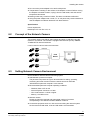
1
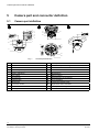
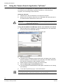
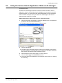
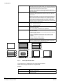
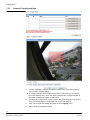
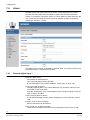
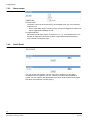
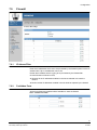
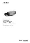
CFMC1315-LP
1/3” 1.3 Megapixel IP Indoor
Dome Colour Camera
Configuration Manual
Building Technologies
Fire Safety & Security Products
Liefermöglichkeiten und technische Änderungen vorbehalten.
Data and design subject to change without notice. / Supply subject to availability.
© 2009 Copyright by
Siemens Building Technologies
Wir behalten uns alle Rechte an diesem Dokument und an dem in ihm dargestellten Gegenstand vor. Der Empfänger erkennt diese Rechte
an und wird dieses Dokument nicht ohne unsere vorgängige schriftliche Ermächtigung ganz oder teilweise Dritten zugänglich machen oder
außerhalb des Zweckes verwenden, zu dem es ihm übergeben worden ist.
We reserve all rights in this document and in the subject thereof. By acceptance of the document the recipient acknowledges these rights
and undertakes not to publish the document nor the subject thereof in full or in part, nor to make them available to any third party without our
prior express written authorization, nor to use it for any purpose other than for which it was delivered to him.
Copyright
Copyright 2009 © Fire & Security Products GmbH & Co. oHG. All rights reserved.
Siemens Fire & Security Products GmbH & Co. oHG confers upon the purchaser
the right to use the software.
It is not permitted to reproduce this document in whole or in part or translate it into
another language without our written consent.
Trademarks
CFMC1315-LP is a trademark of Fire & Security Products GmbH & Co. oHG.
Microsoft is a registered trademark and Windows a trademark of Microsoft
Corporation. All other products or company names referred to explicitly in this
manual are mentioned only for purposes of identification or description and may be
trademarks or registered trademarks of their respective owners.
Contacting us
If you have questions or suggestions regarding the product or this documentation,
please contact your local SIEMENS representative.
Siemens Building Technologies
Fire & Security Products GmbH & Co. oHG
D-76181 Karlsruhe
You can also visit our Web site at www.sbt.siemens.com.
Training courses
Siemens Fire Safety & Security Products provides training courses for all products.
About this document
This manual provides the information you will need in order to install and configure
a Solaris™ Dome unit. We recommend that you read through it at least once
before you begin the installation.
Orientation guide
Tips and information
Contents
1
1.1
1.2
1.2.1
1.2.2
1.2.3
1.3
1.4
Safety .......................................................................................................7
Target readers...........................................................................................7
General safety precautions .......................................................................7
Transport...................................................................................................7
Installation .................................................................................................7
Cleaning ....................................................................................................8
Meaning of the signal words .....................................................................8
Meaning of the hazard symbols ................................................................8
2
EU directives ...........................................................................................9
3
Specifications........................................................................................10
4
4.1
Ordering Data ........................................................................................11
Package Contents...................................................................................11
5
5.1
5.1.1
5.1.2
5.1.3
5.1.4
5.1.5
5.1.6
5.1.7
5.1.8
Camera part and connector definition................................................12
Camera part definition.............................................................................12
Alarm out terminal ...................................................................................13
Alarm in terminal .....................................................................................13
Power IN connector.................................................................................13
Audio in ...................................................................................................13
Audio out .................................................................................................13
IP/TV switch ............................................................................................13
Reset button............................................................................................13
Default button..........................................................................................13
6
6.1
6.2
6.3
6.4
6.5
6.6
6.7
6.8
Installing the camera ............................................................................14
Precautions .............................................................................................14
Concept of the Network Camera.............................................................15
Setting Network Camera Environment ...................................................15
Connecting the Camera and Personal Computer by Network................16
Using the Camera Search Application "IpFinder" ...................................18
Using the Camera Search Application "Web cam IP manager" .............19
Log-in Screen..........................................................................................20
Viewing and Listening .............................................................................20
7
7.1
7.2
7.2.1
7.2.2
7.2.3
7.3
7.3.1
7.3.2
7.3.3
7.3.4
7.4
7.4.1
7.4.2
7.4.3
7.4.4
Configuration.........................................................................................23
Compression ...........................................................................................23
Network Settings .....................................................................................27
Basic Settings .........................................................................................27
DDNS Settings ........................................................................................28
FTP Server..............................................................................................28
Image Parameters...................................................................................29
Camera - Basic settings..........................................................................29
Camera-mask zone settings ...................................................................31
Camera-Cropping settings ......................................................................32
Camera-OSD settings.............................................................................33
Alarm.......................................................................................................34
External digital input 1.............................................................................34
Motion detection settings ........................................................................35
Alarm output............................................................................................36
Audio Event.............................................................................................36
3
Siemens Building Technologies
Fire Safety & Security Products
01.2009
7.5
7.5.1
7.5.2
7.5.3
7.5.4
7.6
7.7
7.8
7.8.1
7.8.2
7.9
7.9.1
7.9.2
7.9.3
7.10
7.10.1
7.10.2
7.10.3
7.10.4
7.11
7.12
Record.....................................................................................................37
FTP recording .........................................................................................37
SD recording ...........................................................................................40
Emailing recording ..................................................................................42
NAS recording .........................................................................................45
Audio .......................................................................................................47
Date/Time................................................................................................48
Access protection....................................................................................49
Administrator ...........................................................................................50
User list ...................................................................................................50
Firewall ....................................................................................................51
IP Adress Filter........................................................................................51
Forbidden Ports.......................................................................................51
Forbidden Protocol..................................................................................52
System ....................................................................................................52
Setting .....................................................................................................52
Update.....................................................................................................53
Configuration ...........................................................................................53
Temperature............................................................................................54
Log ..........................................................................................................55
Notice ......................................................................................................55
8
8.1
8.2
8.3
Utility program application...................................................................56
NAS player setup ....................................................................................56
Audio record setup ..................................................................................56
Firmware update setup ...........................................................................57
9
Maintenance...........................................................................................58
10
Disposal .................................................................................................58
11
Keyword index.......................................................................................59
4
Siemens Building Technologies
Fire Safety & Security Products
01.2009
5
Siemens Building Technologies
Fire Safety & Security Products
01.2009
Safety
1
Safety
1.1
Target readers
The instructions in this document are designed only for the following target
readers:
Target readers
Qualification
Activity
Condition of the
product
Operational startup
personnel
Technical training for
building or electrical
installations.
Puts the product into
operation for the first
time, or changes the
existing configuration.
The product is installed
but not yet configured,
or the existing
configuration is to be
changed.
Training on the product
is recommended.
1.2
General safety precautions
z Read the general safety precautions before installing, configuring and operating
the device.
z Keep this document for reference.
z Always pass this document on together with the product.
z Please also take into account any additional country-specific, local safety
standards or regulations concerning project planning, operation and disposal of
the product.
z Follow all warnings and instructions marked on the device.
Liability claim
z Do not make any changes or modifications to the device unless they have been
approved by the manufacturer.
z Use only spare parts and accessories that have been approved by the
manufacturer.
1.2.1
Transport
Damage during transport
z Keep the packaging material for future transportation.
z Do not expose the device to mechanical vibrations or shocks.
1.2.2
Installation
z It is recommended that all preparatory work (e.g. fitting of accessories) be
carried out in a workshop prior to final installation.
Radio interference with other devices in the environment
z When handling modules that are susceptible to electrostatic discharge, please
observe the ESD guidelines.
7
Siemens Building Technologies
Fire Safety & Security Products
01.2009
Safety
Damage due to unsuitable mounting location
z The environmental conditions recommended by the manufacturer must be
observed. See section 4: Ordering Data.
z Do not operate the device in dusty places.
z Do not expose the device to mechanical vibrations or shocks.
z Protect the device against moisture.
z Place the unit on a stable surface that will hold its weight.
z The mounting surface must be solid and non-combustible.
z Do not operate the device close to sources of powerful electromagnetic
radiation.
Danger of electrical shock due to incorrect connection
z Connect the device only to power sources with the specified voltage. Voltage
supply requirements can be found on the mains adapter.
z Make sure the device is permanently connected to the electricity supply; a
readily accessible disconnect device must be provided.
z This device is designed to work with 12 V DC / 24 V AC-systems or PoE. Do not
connect the device to any other power systems.
1.2.3
Cleaning
Do not touch the imaging surface of sensor. Use a soft cloth moistened with
alcohol to clean the surface if it is touched accidentally.
1.3
Meaning of the signal words
The severity of a hazard is indicated by the following written signal words.
1.4
Signal word
Type of risk
DANGER
Imminent danger of death or severe bodily injury
WARNING
Possible danger of death or severe bodily harm
CAUTION
There is a risk of minor to medium injuries or damage to property.
IMPORTANT
Malfunctioning may result
Meaning of the hazard symbols
The nature of the hazard is indicated by icons.
Warning of a hazard
Warning of dangerous electrical voltage
Tips and information
8
Siemens Building Technologies
Fire Safety & Security Products
01.2009
EU directives
2
EU directives
The product complies with the requirements of the following EU directives. The EU
declaration of conformity is available from:
Siemens Building Technologies
Fire & Security Products GmbH & Co. oHG
76181 Karlsruhe
Germany
European Directive 2004/108/EC “Electromagnetic Compatibility”
Compliance with the European Directive 2004/108/EC has been proven by testing
according to the following standards:
Emitted interference:
EN 61000-6-3
Resistance to interference:
EN 50130-4
EN 55022 Class B
9
Siemens Building Technologies
Fire Safety & Security Products
01.2009
Specifications
3
Specifications
Image System
Description
Image sensor
1/3” progressive ExviewHAD CCD, 1.3 Megapixels
Effective pixels
1280 (H) x 960 (V)
Image compression method
Motion JPEG/ MPEG4
Image frame rate
SXGA: 1280 x 960 at 12.5 fps max.
VGA 640 x 480, QVGA 320 x 240 at 25 fps max.
Cropping window
Simultaneous Video-transmission of up to 5 independent cropping windows, free configuration
in size and position@ 5 fps max (MJPEG mode only)
Video out(for installation)
1 Vpp 75 Ohm BNC composite video, (either CVBS or IP video selectable by switch)
Electronic
Sync system
Internal
Build-in Lens
High Quality Megapixel Lens: f=3.0 – 9 mm, F1.2
Gamma correction
0.45/1.0
Min illumination
0.4 lx (F1.2, AGC ON)
White balance
Auto (2500 K – 10000 K) / Manual (1500 K – 15000 K) / Preset
Electronic shutter
1/25 - 1/10,000 sec; support long shutter 1/4 s
BLC
On/Off, BLC1 - BLC6
Audio
Two way Audio; Full duplex, G.726 selectable
Alarm
1x Alarm in, 1x Alarm out
SD card slot
Support up to 2 GB SD card (2 GB SD-card included at delivery)
Internal Microphone
Yes
Motion detection
1 window selected by mouse & 3 level sensitivity
Power Supply
Power requirement
12 V DC / 24 V AC , 50 Hz or PoE
Power consumption
< 7W
Power connector
Power connector 2 pin screw terminal block
Environment
Operating temperature
-10 to +50 C
Operating humidity
80 % RH or less
Storage temperature
-20 to +60 °C
Network
Ethernet
1 x 10/100 based-T Ethernet connection for LAN/WAN
Internet protocol
TCP/IP, UDP, HTTP, SMTP, DNS, DHCP, NTP, ARP, ICMP, DDNS, FTPc, FTPs, DHCPc,
RTSP, RTCP, RTP, IGMPv3
Security
Multiple password for Admin, Advanced Users and Users
Control interface
IE browser 6.0 or above
I/O connector
Network port
RJ45 with control LED
Video output
2 pin jack (for video setup only)
Audio in & out connector
3.5 mm phone jack
Alarm connector
1x alarm in/ 1x alarm out
Power connector
3 pins spring terminal block
LED
Orange stand for Network online, Green stand for system ready
Mechanism
Angle control (3-AXIS)
Yes
Panning range
350 deg
Tilting range
146 deg
Dimensions (L x D)
128 x 140 mm
Weight
0.65 kg (camera only)
10
Siemens Building Technologies
Fire Safety & Security Products
01.2009
Ordering Data
4
Ordering Data
Type
Art-No.
Description
Weight
CFMC1315-LP
S54561-C81-A1
1/3” 1.3 MP Indoor IP Dome Colour
Camera 12 V DC / 24 V AC,
50 Hz or PoE
0.65 kg
4.1
Package Contents
z CCD IP dome
z Documentation CD
z Utilities CD
z Installation instruction (English, German, French, Spanish, Italian)
z SD card (2 GB)
z Wall plugs (4x)
z Mounting screw (4x)
z Mounting template for installation
z Monitor out cable *1
11
Siemens Building Technologies
Fire Safety & Security Products
01.2009
Camera part and connector definition
5
Camera part and connector definition
5.1
Camera part definition
Black
Brown
Red
8
Orange
Red+
Black-
COM
Alarm Out
1
GND
Alarm In
2
Power In
3
4
Black Audio Out
White Audio In
12
SD CARD
DEFAULT
21
P
16
5
13
6
9
10
14
15
7
22
SIEMENS
19
17
11
20
18
23
Fig. 1
Camera part definition
1
Alarm out terminal
13
Tilt adjust screws
2
Alarm in terminal
14
Horizontal adjustment ring
3
Power IN connector
15
Zoom lever
4
Audio out (φ3.5mm)
16
Focus lever
5
Audio in (φ3.5mm)
17
Reset button
6
Body casing
18
Bottom casing
7
SD Card slot
19
MON (Monitor out connector)
8
Default button
20
IP/TV selection
9
Microphone
21
Loosen the locking screw
10
Front cover screw
22
Open/close dome indication
11
Dome cover
23
Fixed point for ceiling mount
12
Pan adjustment bracket
12
Siemens Building Technologies
Fire Safety & Security Products
01.2009
Camera part and connector definition
5.1.1
Alarm out terminal
YELLOW: ALARM OUT
Alarm output port
BLACK: COM
5.1.2
Alarm in terminal
RED: ALARM IN
External alarm input
ORANGE: GND
5.1.3
Power IN connector
WHITE: Power POWER DC12V / AC24V
BLACK: Power +
5.1.4
Audio in
White
5.1.5
WHITE AUDIO JACK: In
Audio in (φ3.5mm)
BLACK AUDIO JACK: Out
Audio out (φ3.5mm)
IP
Video out through Ethernet
TV
BNC composite video out for installation purpose
RESET
System re-start
DEFAULT
Return to factory default by pressing button for 5
seconds
Audio out
Black
5.1.6
5.1.7
5.1.8
IP/TV switch
Reset button
Default button
13
Siemens Building Technologies
Fire Safety & Security Products
01.2009
Installing the camera
6
Installing the camera
6.1
Precautions
SD Memory card
Please install the SD memory card before switching on the camera as the system can not detect the
insertion of SD card during operation.
z There is a limit to the number of rewrites that is possible with the SD memory
card. Replacing the SD memory card when performing periodic maintenance of
the camera is recommended.
z The camera supports the following SD memory cards. Do not use memory cards
with other specifications. SD memory card: 64, 128, 256, and 512 MB, 1 and 2
GB SD memory cards (3.3 V) supported.
Physical interface: Part 1. Physical Layer Specification; Version 1.01
z Images may not be recorded or read correctly if an unsupported SD memory
card is used with the camera
z Carefully read the manual, precautions on use, and any other information
supplied with a purchased memory card.
z An SD memory card can be used for the loop recording of images. The life-span
(number of rewrites possible) of an SD memory card is greatly affected by the
capacity of the SD memory card. The use of a 128, 256, or 512 MB, 1 or 2 GB
large-capacity SD memory card is recommended for loop recording.
z Do not use a memory card containing the data recorded by another device with
the camera as this may result in the camera not functioning correctly.
z Do not modify, overwrite the data, or change the folder name of an SD memory
card. It may result in the camera not to function correctly
z Data recorded with the camera do not comply with the image file format Exit and
the DCF standard. If the SD memory card is to be removed to play images, use
a personal computer to play the images. Other devices may not be capable of
doing so.
Power adaptor
CAUTION
Be sure to use only the suitable power adapter. Using a wrong power adapter
may cause the camera to malfunction, heat up, or catch fire. Before using the
power adapter, carefully read and observe the Important Safety Instructions and
the notes below.
z Do not allow the connectors on the power adapter to come into contact with any
other metal object as this may result in short circuit.
z To connect the power adapter, firmly insert the plug end of the cable into the
power terminal. Do not insert the plug into other jacks as this may cause a
malfunction.
z When removing the connection cable, disconnect the cable by holding its plug.
Do not disconnect the cable by pulling on the cable.
z Do not drop the power adapter or subject it to strong impact.
14
Siemens Building Technologies
Fire Safety & Security Products
01.2009
Installing the camera
z Do not use the power adapter in hot and humid places.
z Temperature increasing on the surface of the adapter is normal. Before moving
the adapter to another location, unplug it from the wall outlet, and wait until its
temperature decreases
z Buzzing noises may come from inside. This does not indicate malfunction.
z Using the power adapter near a radio, TV, or cell phone may cause interference.
Use the adapter at sufficient distances from these devices.
Specifications
Power requirement
Rated input: AC 24V /DC 12V, 1A
6.2
Concept of the Network Camera
The network camera can deliver video images and audio in real time using the
Internet or an intranet. The camera is equipped with Ethernet (RJ-45) 10BASET/100BASE-TX network interfaces.
It can be used in various indoor environments.
SIEMENS
Ethernet
SIEMENS
Hub
Hub
Switch
PC
SIEMENS
SIEMENS
6.3
Setting Network Camera Environment
Items needed for network camera monitoring system
z Administrator's personal computer
The personal computer that is given all authorities for setting, operating,
monitoring and other functions with the network camera is called the
"administrator's personal computer" in this manual.
z Recommended personal computer operating conditions
– Windows Vista or XP as OS
– Internet Explorer Version 6.0 or later
– CPU: Intel Pentium 4.2 GHz or higher
– Memory: 512 MB or more
z Network camera
Please purchase the required and appropriate number of cameras
corresponding to the desired camera installation locations.
z Connection equipment such as a hub and router suiting the network system
environment and LAN cable, a Cat 5e LAN cable is recommended.
15
Siemens Building Technologies
Fire Safety & Security Products
01.2009
Installing the camera
z Camera search application "IpFinder"
Install this application from the CD-ROM supplied as an accessory. (Double-click
"ipfinder_Setup.exe" in the CD-ROM and install the application in accordance
with the instructions on the screen)
6.4
Connecting the Camera and Personal Computer by Network
IP Address
To connect to the network, the administrator needs to set the network camera IP
address.
There are two options to set the IP address.
– Entering an IP address manually (factory default)
– Obtaining an IP address automatically from the DHCP server
z Entering the IP address manually.
Your camera is set to this mode at factory with IP address: 192.168.0.10, so you
need to enter this IP number manually to access camera at the first time.
z Obtaining an IP address automatically from the DHCP server
If your network is using DHCP server, you do not need to change the IP address
of the camera. But be sure to set DHCP ON/OFF to ON in "Network
settings/Basic".
NOTE
The IP address of the network camera is sometimes updated or changed from time to time when the
DHCP server is used. For this reason, the network camera sometimes cannot be connected due to an
IP address change if the network camera is accessed using the previously set IP address.
To enable accessing the network camera in this case, a fixed IP address needs be set with the
network camera by setting an IP address through manual input. Please read the instruction manuals
of the network system equipment also carefully such as the router, hub and modem.
When entering the IP address manually, set DHCP ON/OFF to OFF in "Network/Basic Settings" and
enter the IP address, subnet mask, default gateway, primary DNS and secondary DNS.
Connection Configuration
Two configurations are available for connection of network cameras.
z Crossover connection
z Connection via a hub, switch, or router
NOTE
z You do not need to assign an IP address to a hub.
z The IP address of your camera after purchasing from the store is automatically set to 192.168.0.10
in case DHCP is not used. Set the IP address of your personal computer in the same subnet. (The
network segment must be the same segment when directly connecting using a cross cable or
connecting through the hub) When connecting more than one camera, connect each camera using
IP Address 192.168.0.10 and change the IP addresses of the second and subsequent cameras to
other IP addresses, such as 192.168.0.11.
z You can also use the LAN port of your broadband router. However, when using the broadband
router, if the DHCP server function is set to "ON", turn on the power after connecting the camera
with the router. The camera gets the IP address from the router's DHCP server and it may not be
192.168.0.10.
For more information, read your user's guide for broadband router.
It is also recommended to set the computer's IP address from the router's DHCP
server.
16
Siemens Building Technologies
Fire Safety & Security Products
01.2009
Installing the camera
For more information, read your computer's user's guide.
Connecting Camera and Personal Computer
1.
Connect LAN cable and turn the power on.
Connect the LAN cable (straight cable) connected to the camera to the hub.
Or, connect the camera to a personal computer with the power turned on
using the LAN cable (cross cable). Connect AC 24V/DC 12V to the power
terminal.
2.
Set the IP address of the personal computer.
– Set the IP address which you are not using other than 192.168.0.10 (camera's
IP address).
– Set the IP address to 192.168.0.20 (and subnet mask to 255.255.255.0) as an
example.
– For details on the procedure, refer to the user's guide of the personal
computer.
3.
Test the camera connection using ping.
– Start a command prompt. Type "ping 192.168.0.10" and press "Enter" key.
– If the "Reply from..." message appears, the connection is correctly
established.
4.
Search the camera by "IpFinder" explained and view a camera image.
– Start "IpFinder" and click the "Search" button.
Confirm that the camera name "nwcam05" is displayed in the camera list.
– Click "nwcam05" to select.
The camera name, IP address and HTTP port No. are displayed in the
"Network Camera Lists" field.
– Double-click the camera in the camera list you wish to log-in.
The screen for inputting the user name and password will appear. Input the
administrator log-in ID and password. (See "Log-in Screen")
– A camera image screen of the network camera will appear.
NOTE
z To view images without using "IpFinder," launch the Internet browser, enter URL
http://192.168.0.10/ in the address box and press "ENTER."
z It takes about10 seconds to activate the camera.
z If a port number other than "80" is set, designate the port number by suffixing it after ":" as in
http://192.168.0.10:88
17
Siemens Building Technologies
Fire Safety & Security Products
01.2009
Installing the camera
6.5
Using the Camera Search Application "IpFinder"
The "IpFinder" is an application for searching network cameras that can currently
be viewed from the administrator's personal computer or a user's personal
computer, and connecting to those cameras.
Setting up "IpFinder"
1.
Insert the CD in the CD-ROM drive of the personal computer.
2.
Double-click the "ipfinder_Setup" file in the CD-ROM and install "IpFinder" in
accordance with the instructions on the screen.
IMPORTANT
"IpFinder" is compatible only with Windows Vista and Windows XP. Glitches
may occur with your personal computer if it is operated by other OS. Do not
install "IpFinder" with other OS.
Using "IpFinder (Web-Cam IP Manager Version 3.0)" to Search for a Camera
Start the Web-Cam IP Manager by loading IP Manager.exe. This application
is found on the CD included with delivery.
1.
Î
The Web-Cam IP Manager program window will open:
Click the Start button.
2.
Î
The Web-Cam IP Manager program window will now display a list of all the
devices available for communication along with their IP and MAC addresses.
Each device's IP address or MAC address is unique.
3.
Select the device whose home page you want to access.
4.
Click the Home page of selected device button.
Î
5.
The home page of the selected device will appear. See Section 6.8: Viewing
and Listening.
To exit without performing log-in, click the Exit button.
NOTE
Set the personal computer to "Administrator authorization" when using "IpFinder."
18
Siemens Building Technologies
Fire Safety & Security Products
01.2009
Installing the camera
6.6
Using the Camera Search Application "Web cam IP manager"
This assumes that:
The Web-Cam IP Manager and all the units are located in the same network
segment. If a device and the Web-Cam IP Manager are not located in the same
network segment, you must ensure that associated gateway (router) passes the
SSDP multicast messages sent by the Web-Cam IP Manager to the network
segment where the device is located.
SSDP (Simple Service Discovery Protocol / network protocol)
Start the Web-Cam IP Manager by loading IP Manager.exe. This application
is found on the CD included with delivery.
1.
Î
The Web-Cam IP Manager program window will open:
Click the Start button.
2.
Î
The Web-Cam IP Manager program window will now display a list of all the
devices available for communication along with their IP and MAC addresses.
Each device's IP address or MAC address is unique.
3.
Select the device whose home page you want to access.
4.
Click the Home page of selected device button.
Î
The home page of the selected device will appear. See Section 6.8: Viewing
and Listening.
19
Siemens Building Technologies
Fire Safety & Security Products
01.2009
Installing the camera
6.7
Log-in Screen
5.
Open the Internet Explorer.
6.
Enter the default IP address: 192.168.0.10.
You can also use Mozilla Firefox. In that case, you have to download the IE Tab
plug-in from the Mozilla Firefox homepage.
This product regards a person who has performed Administrator Log-in as an
"administrator". Administrator Log-in can perform all functions.
Administrator Log-in
Search the camera by "IpFinder", double-click the camera you wish to log-in.
1.
Î
The screen for inputting the user name and password will appear.
Input the administrator log-in ID and password in the user name and
password fields and click the OK button.
2.
Î
The administrator log-in screen and camera image screen will appear.
And the administrator log-in ID and password are set to "admin" and to
"admin" respectively by default.
IMPORTANT
6.8
Administrator Log-in allows rewriting of all settings. Be certain to change the
administrator log-in ID and password already set in the camera by default, to
ensure camera security. Keep the new administrator log-in ID and password
handy for future use. To change the administrator log-in ID and password, see
"Access protection” section.
Viewing and Listening
Images of the network camera can be viewed through the Internet browser of your
personal computer.
Preparations before displaying
z Enable cookies
z Set "Browser setting when proxy server is used" when a proxy server is used.
z Change "security" in Internet options as follows.
1.
Click "Internet Option" on the tool menu.
2.
Click the Security tab.
20
Siemens Building Technologies
Fire Safety & Security Products
01.2009
Installing the camera
3.
Click the "Intranet" icon if the camera to be operated is inside the intranet,
clicking the "Internet" icon if the camera is on the Internet.
4.
Click "Level customize."
5.
Check the following radio buttons in the displayed list:
– "Enable" for "ActiveX control and plug in execute"
– "Enable" for "Execution of script of ActiveX control marked safe even when
script is executed"
– "Enable" for "Download of signed ActiveX control"
Click "OK."
6.
Log-in the camera
z Enter the camera IP address (default: 192.168.0.10) in the browser address bar
to launch the camera login screen.
z See "Log-in Screen" portion for the log-in method.
z When the security warning screen (VeriSign) appears on the first use of the
system, click "Yes."
NOTE
Administrator authorization is needed to install "Active-X control." Install "Active-X control" after
changing the personal computer setting to "Administrator authorization."
Browser setting when proxy server is used
In case a proxy server is used, setting of the browser to bypass the proxy server
during communication with the network camera is recommended.
1.
Launch the browser.
2.
Choose "Internet option" on the tool menu.
3.
Click "Connect" tab.
4.
Click "LAN Setting."
Î
5.
The screen for setting a local area network (LAN) will appear.
Check if the checkbox "Will use a proxy server" is checked.
– If the checkbox is not ticked
The browser is not set to use a proxy server. Click "Cancel" and quit setting.
– If the checkbox is checked
Click "Detail setting." A proxy setup screen will appear.
6.
Enter the IP addresses of the network cameras in the field marked "Do not
use the proxy server with addresses started with the following.
7.
Click "OK."
When Windows XP SP2 is used: Click "Install" for "Active-X control."
NOTE
● A proxy server protected by a firewall sometimes cannot be connected to the network camera.
Consult the network administrator so as to avoid impacts on network camera operations.
● Communication with the network cameras via a proxy server may cause some problem. Install the
network cameras after consulting the network administrator.
● Using the network cameras via a proxy server sometimes takes a long time till images are displayed
after log-in or reduces the frame rate of delivered images.
21
Siemens Building Technologies
Fire Safety & Security Products
01.2009
Installing the camera
Camera Image Screen
When using Windows XP SP2
If fails to display the Camera Image screen, operate as follows.
1.
Choose "Pop-up Blocker" on the tool menu.
2.
Choose "Always Allow Pop-ups from This Site...".
Components of unit home page
OSD
this function enables OSD setting including title name, date and
time
E
this function is PTZ control and preset setting
Microphone
alarm out stop
Speaker
alarm in stop
Pause
passed live image
Play
show live image
Language
standard setting is English. Website supports 10 different
languages for end user choice
PTZ operating panel
the PTZ operating panel enables a pan/tilt/zoom drive and the
current pan/tilt position is stored under the selected position
number. Up to 64 positions can be stored for the network camera
Image stream 1 & stream 2
Two streams, 1 & 2 available for selection. Stream 1 can be set to
JPEG and MPEG4, but only JPEG available for Stream 2
22
Siemens Building Technologies
Fire Safety & Security Products
01.2009
Configuration
7
Configuration
7.1
Compression
Image mode
z Both functions of JPEG and MPEG4 are effective.
z Two streams, 1 & 2 available for selection. Stream 1 can be set to JPEG and
MPEG4, but only JPEG available for Stream 2
JPEG
Following settings are enabled when "Compression Mode" is set to "JPEG".
z Resolution
Configure resolution. Higher Resolution results in larger image
Possible settings:1280 x 960 (SXVGA)/640 x 480 (VGA)/320 x 240 (QVGA)
z Compression Ratio
Set quality of delivered images. The size of image files (JPEG files) varies in
accordance with compression ratio. Five options are available from Low to High
– Low compression: This setting produces highest image quality. The file size
increases.
– Mid compression: Standard setting.
– High compression:
This setting produces lowest image quality. The file size
decreases.
23
Siemens Building Technologies
Fire Safety & Security Products
01.2009
Configuration
z Frame Rate: seven frame rates – 1, 2 , 3, 5, 10, 12, 25 – are available for
selection.
MPEG4
Following settings are enabled when "Compression Mode" is set to "MPEG4".
z Resolution: 640 x 480 and 320 x 240 available.
z Bit Rate: 6 modes including 256,512,1024,2048,3072 and 4096 kb/s
z GOP: default is 29. It means 1 I frame plus 28 P frame. End user can adjust
1~64 level.
Unicast Streaming
Ready for MPEG4 and JPEG streaming
z RTSP Port Number – specify the port number you would like to use for RTSP
protocol, default is 554
z VIDEO Port Number - specify the port number you would like to use for video
streaming, default is 5000
Multicast Streaming
Ready for MPEG4 and JPEG streaming
z Multicast Address: specify the multicast address
z RTSP Port Number – specify the port number you would like to use for RTSP
protocol, default is 554
z VIDEO Port Number - specify the port number you would like to use for video
streaming, default is 5000
24
Siemens Building Technologies
Fire Safety & Security Products
01.2009
Configuration
How to operate RTSP
NOTE
You need to prepare suitable RTSP player such as Quicktime or VLC to receive the data streaming
first then execute application program. This application is found on the CD included with delivery.
z Perform VLC
1.
Select Open then click the Network tab.
2. Click RTSP then fill in web address
rtsp://<IP address>:<rtsp_port>/livestream
3.
Click OK.
For example: rtsp://192.168.0.194:554/livestream. Regarding default
value of RTSP port, it’s based on which stream you select.
VCL media player
25
Siemens Building Technologies
Fire Safety & Security Products
01.2009
Configuration
z Perform Quicktime
1.
Select Open URL.
2.
Then fill in rtsp://<IP address>:<rtsp_port>/livestream
3.
Click OK.
For example: rtsp://192.168.0.194:554/livestream. Regarding default
value of RTSP port, it’s based on which stream you select.
Quicktime livestream
26
Siemens Building Technologies
Fire Safety & Security Products
01.2009
Configuration
7.2
Network Settings
You can setup your camera basic setting, DDNS, and FTP server by selecting
Network Settings in the Configuration menu..
7.2.1
Basic Settings
Basic
Camera Name
Input your camera name here. The default name is “nwcam05”.
Camera Name Enable
Network
DHCP
The IP address is automatically obtained when you select ON;
otherwise, select OFF to manually setup the network setting.
IP Address
Input your IP address here when you select DHCP off.
Subnet Mask
Please use default number: 255.255.255.0
Default Gateway
leave blank as default setting. It is not necessary to enter Default
Gateway if it is not used.
Ask your Network Administrator for Default Gateway information.
Primary DNS
(same as above)
Secondary DNS
(same as above)
Port
Stream1-Stream2,
cropping1-5:
We recommend to use the default, if need to change please check
with system administrator.
UPnP
If this item is selected “ON”, the camera can be detected automatically
by PC. No necessary to have IpFinder installed.
AUDIO output
If this item is selected “ON”, a voice message of camera’s IP address
can be delivered to external speaker via Audio output port.
27
Siemens Building Technologies
Fire Safety & Security Products
01.2009
Configuration
Bandwidth Control
OFF: The network Camera will stream images at the maximum frame
rate allowed by the network.
ON: The Network Camera will display images up to the set bandwidth;
using a lower bandwidth results in lower frame rates.
7.2.2
DDNS Settings
This function is available when registering with DDNS provider. Select ON to
enable the DDNS function; input your DDNS server, User ID, password and
password (confirm), and then presses save to save your settings.
To transmit the camera’s host name to a DHCP server you have to configure this in
the DDNS Settings.
7.2.3
FTP Server
If you wish to enable FTP function, select ON to activate FTP function. Input your
Login ID, Password, Password (confirm), and number of maximum connection in
Max Simultaneous Connections. Press “Save” to save your setting.
NOTE
The purpose is to download or delete the directories/files in SD memory card.
28
Siemens Building Technologies
Fire Safety & Security Products
01.2009
Configuration
7.3
Image Parameters
7.3.1
Camera - Basic settings
Basic items such as size and quality of delivered images of the camera can be set.
Select "Image Parameters" in the Configuration menu.
1.
Î
A sub menu for Camera Settings will appear.
Click "Basic" in the sub menu.
2.
Î
The "Camera - Basic Settings" screen will appear.
3.
Configure the individual settings.
4.
Click the Save button to save your settings.
The settings will not be reflected unless the Save button is clicked.
Image Colour
Preset image
Four types of specific application conditions such as Indoor, outdoor,
tunnel and casino can be selected for quick and easy setup purpose.
EV Adjustment
19 steps of offset level from -9 to +9 are available to adjust the internal
reference brightness level. Images become brighter as higher the level
is and becomes darker as lower the level is.
Auto Gain Control
The circuit gain is adjusted automatically between Min. and the
selected value, "Low," "Mid" and "High” where the sensitivity
characteristic increases in the order of "Low," "Mid" and "High”. Noise
at dark will be more noticeable when Auto Gain Control is near "High".
NOTE:
If sensitivity is still too low after setting Auto Gain control, set the high
limit value of the slow shutter, to further increase sensitivity.
Shutter Speed
Default is: 1/25s. The shutter speed is set at automatic, 1/25 s, 1/50 s,
1/120 s, 1/250 s, 1/1000 s and 1/10000 s. The network camera will
adjust the aperture according to the amount of ambient light.
29
Siemens Building Technologies
Fire Safety & Security Products
01.2009
Configuration
Slow Speed Shutter
The Slow shutter can be turned “ON” if the sensitivity is still not so
good under “High” gain condition at dark. The optimum image level can
be maintained by appropriate gain and shutter combination which are
determined automatically inside camera system.
As slow shutter activates, the exposure time becomes longer and
frame rate becomes smaller. Blurred images sometimes are prominent
with moving objects.
Back Light Compensation
Set an area for backlight compensation. If backlight compensation is
activated, the camera performs the exposure control only within the
specified area.
Backlight compensation is a function that achieves the brightness of a
selected area to an optimum image level. This function is necessary
when an auto iris lens tends to close due to an intense light coming
from the back of the object in the area to be viewed so that areas
become dark and visibility deteriorates. In this case, set the area so
that the portion to be viewed is within the selected area. The area size
is roughly as shown in Fig. 2 below.
Sharpness
Set a sharpness effect.
“Sharp”: sharpness is strong.
“Soft”:
sharpness is weak.
Gamma
“1”: May be selected for some specific area, such as FA application for
obtaining true video data.
White Balance
Set the white balance values to meet the environment condition for
best colour rendition.
“0.45”: This is default, suitable for CCTV application
z “AWB”: the colour of camera is automatically adjusted according to
external lighting condition.
z “Manual”: Adjustable by user manually, this is useful for some
specific condition which AWB may be unaffordable to perform
correctly.
z “Indoor”: Default for 3200K condition
z “Outdoor” Default for 5100K condition
Iris Adjustment
1. OFF
4. Center 1/3
19 steps of offset level from -9 to +9 are available to adjust the image
level for an DC auto iris lens. Images become brighter as higher the
level is and becomes darker as lower the level is.
2. Upper 2/3 (Area designation)
5. Center 1/6 (Area designation)
Fig. 2
3. Lower 2/3 (Area designation)
6. Left (Area designation)
7. Right (Area designation)
Back Light Compensation
(The image level of shaded parts is maintained appropriate)
When OFF, rear light correction is not performed.
Picture
Picture Flip
Set image to be upside or down. Select ON or OFF to activate or
deactivate the flip function.
Picture Mirror
Set image to be left or right. Select ON or OFF to activate or deactivate
the mirror function.
30
Siemens Building Technologies
Fire Safety & Security Products
01.2009
Configuration
7.3.2
Camera-mask zone settings
1.
Tick the checkbox “ON”, then click “Set Mask Zone” to start mask setting
2.
Use the mouse to drag a mask rectangle on the screen, click “OK” to
complete the selection.
3.
Click “Save” to enable the mask setting.
NOTE
Max. 8 masks can be set on the screen.
The mask function is not supported when the cropping function is on.
31
Siemens Building Technologies
Fire Safety & Security Products
01.2009
Configuration
7.3.3
Camera-Cropping settings
Tick the "ENABLE" checkbox and fill in the name, then click “Set Cropping
Area” to start cropping setting.
1.
Î
A cropping setting screen will pop-up as shown, select one type of cropping
from VGA, QVGA, 4CIF, 2CIF, CIF, QCIF, and free size on bottom screen, a
red-mesh rectangle will appear on the screen.
2.
To select the cropping area, move mouse to the preferred position on screen,
then click the left button, the red-mesh will jump to that position.
3.
Click “OK” to finish the setting, and return to the Cropping menu.
4.
Click “SAVE” to enable the setting.
32
Siemens Building Technologies
Fire Safety & Security Products
01.2009
Configuration
NOTE
Up to 5 cropping areas can be set on the screen.
The MPEG4 function is not supported when the cropping function is on.
7.3.4
Camera-OSD settings
This function setups the text position and colour of camera name, Alarm text or
DATE/TIME on the screen. Of course, the corresponding ENABLE flag for each
item shall be ”ON” to activate this function, such as camera name Enable in
Network setup, Text enable in Alarm setting and Display in DATE/TIME setting.
33
Siemens Building Technologies
Fire Safety & Security Products
01.2009
Configuration
7.4
Alarm
External alarms and motion sensors can be set. Connecting a sensor or other
device to the alarm input terminal notifies an alarm when the sensor detects a
trouble. For example, mounting a sensor on a door notifies an alarm each time the
door is opened. By setting the motion sensor to activate, an alarm is notified by
detecting a change in a screen.
One Alarm input1 terminal is indicated on external cable. You need to define some
parameters before u sing the alarm function.
7.4.1
External digital input 1
z Set an "Alarm Input"
ON: Detects an external alarm.
OFF: Does not perform alarm detection.
Î
The following functions will be enabled if “ Alarm Input” is set to “ON”
z Set "Input type" for alarms
Normally Opened (NO): A dry-contact detecting way, opened if nothing occurs
but closed in case of an alarm.
Normally Closed (NC): A dry-contact detecting way, closed if nothing occurs but
open in case of an alarm.
z Set "TEXT Enable" for alarms
A noticeable message of alarm can be displayed on screen if this item is set to
“ON”.
z Enter "Text" for alarm message
Max 24 characters can be entered.
z Set "Audio out" for alarm message
Audio alarm message can be sent to external speaker if this item set to “ON”.
34
Siemens Building Technologies
Fire Safety & Security Products
01.2009
Configuration
NOTE
A speaker with amplifier inside shall be connected to AUDIO out jack on rear panel.
7.4.2
Motion detection settings
The setting is similar to alarm input with some additional functions:
z Motion detection
– Set on, open motion detection function.
– Default is off, close motion detection function.
z Area
– Click “Set motion area”, an image screen will pop up.
– Select the interested area by dragging the mouse.
z Sensitivity
Set "Sensitivity."
– High: An alarm will be triggered with even small changes in brightness within
the defined area.
– Mid: Intermediate between High and Low.
– Low: An alarm will be triggered with a major change in brightness within the
defined area.
z Text Enable
– Select ON or OFF to define whether an additional alarm text defined in the
Text field is to be overlaid on the video image.
z Text
– Define an individual text for alarm overlay.
z Audio Output
– Select ON or OFF to define whether an additional audio message (*.wav),
pre-recorded on the SD card, is to be output via the Audio out connector.
z Event
Pre-recorded voice files with extension .wav that have been uploaded to SD
memory card in advance can be selected as voice alarm message. Max. 4 kinds
of audio source can be selected.
35
Siemens Building Technologies
Fire Safety & Security Products
01.2009
Configuration
7.4.3
Alarm output
z Alarm mode:
The alarm output can be turned OFF or be activated when any of the following
events occurs:
– Event: Once alarm input1 or alarm input 2 or motion is triggered, the alarm out
will be triggered immediately as well.
z Output hold time:
Set a time to hold alarm output. Choose from 0, 5, 10, 15, and 30seconds. This
function is used when connecting to alarm output terminals and activating a
siren, buzzer or emergency light.
7.4.4
Audio Event
You can choose which audio *.wav file you want to upload as a voice alarm
message to the SD card from your PC. There are 4 audio events available for
upload. You can select in the appropriate menu which audio event is to be played
with which event (Motion or Alarm input 1).
36
Siemens Building Technologies
Fire Safety & Security Products
01.2009
Configuration
7.5
Record
7.5.1
FTP recording
You can save image files via FTP. Set up your FTP recording conditions first, then
identity your FTP sever 1 and 2.
FTP recording conditions
You can store your image files based on your scheduled recording, or recording by
alarm, or recording by motion.
z Scheduled Recording
Determine the recording condition: STOP, all day, schedule 1 or schedule 2 from
the recording schedule table for all days from Monday to Sunday.
37
Siemens Building Technologies
Fire Safety & Security Products
01.2009
Configuration
z Recording by Alarm
Configure "Alarm input setting" first.
Then select the recording format:
– Record source: choose JPEG or MPEG4 format
– Record frame
Set the number of images to be recorded immediately after an alarm occurs.
Images of the moment when an alarm occurs are not included.
1, 2, 5, 10, 30 and 60 frames can be selected if JPEG format selected. No
need for MPEG4 format
– Recording cycle
Set a time interval for alarm recording 1, 2, 5, 10, 30, 60, 90, 120 s can be
selected for JPEG format, no need for MPEG4 format
– Recording time:
If MPEG4 selected, the recording time can be set to 2, 5, 10 s.
– Record file name
Under transfer image section, the file name arranged by FTP server is time
stamp based. With Time Stamp based, the record file name will be formatted
with the desired file name, time and date as the file name. You can enter the
file name or leave it blank.
z Recording by Motion
Configure "Motion Detection Setting" first.
All the other settings are same as recording by alarm as above.
FTP Server Settings - Server 1 and 2
Please follow your FTP setting to setup FTP server name, Login ID, Password,
FTP port number, FTP mode, and FTP connecting method.
38
Siemens Building Technologies
Fire Safety & Security Products
01.2009
Configuration
z FTP server name: Input a server name or address
z Login ID: Limited only to users who have authority to access the server.
z Password: Input the registered password associated with Login ID.
z Password (Confirm): Re-enter the password
z FTP Port Number: set “21” as default
z FTP Mode
PORT mode: This mode is for most FTP applications
PASV mode: This mode is used when the camera's network environment is
behind a firewall.
z FTP Connecting Method
Reconnect: The network camera logs in/out for each file transfer
Continuous Connection: The network camera is always in connection.
Connecting method
You can choose to save your image files to either FTP server 1, 2, or automatically
switching servers.
SD Card Back Up if FTP Fail
The network camera automatically stores images in the SD card when images
cannot be recorded in the server due to a network failure, or other trouble.
39
Siemens Building Technologies
Fire Safety & Security Products
01.2009
Configuration
The stored images can be transferred to the FTP server when the network status
or other troubles are resolved.
Function ON/OFF: Select ON to active SD card FTP back up function.
Accumulation Cycle: Set a time interval in seconds for images to be stored. (Time
interval: 1, 2, 5, 10, 15, 30, 60 or 120 seconds)
Overwrite: Overwrite when SD card reaches the maximum capacity and start with
oldest stored images.
7.5.2
SD recording
z Conditions
Select whether images are to be stored on the SD card by:
Time schedule, alarm input, motion alarm or network loss.
1.
Configure the individual settings as described below.
z Overwrite
ON: Records are overwritten beginning with old records when the capacity of the
SD memory card becomes full during recording.
OFF: Recording is stopped when the capacity of the SD memory card becomes
full during recording.
40
Siemens Building Technologies
Fire Safety & Security Products
01.2009
Configuration
z Scheduled Recording
Determine the recording condition: STOP, all day, schedule 1 or schedule 2 from
the recording schedule table for all days from Monday to Sunday.
z Recording by Alarm
Configure "Alarm input setting" first.
Then select the recording format:
– Record source: choose JPEG or MPEG4 format
– Record frame
Set the number of images to be recorded immediately after an alarm occurs.
Images of the moment when an alarm occurs are not included.
1, 2, 5, 10, 30 and 60 frames can be selected if JPEG format selected. No
need for MPEG4 format.
– Recording cycle
Set a time interval for alarm recording 1, 2, 5, 10, 30, 60, 90, 120 s can be
selected for JPEG format. No need for MPEG4 format.
– Recording time:
If MPEG4 selected, please set the recording time to 2, 5, or 10 s.
z Recording by Motion
Perform "Motion Detection Setting" first.
All the other settings are same as recording by alarm as above.
z Recording by Network loss
Select network recording. After network loss, the network camera automatically
stores images based on your settings.
41
Siemens Building Technologies
Fire Safety & Security Products
01.2009
Configuration
– Recording cycle
Set a time interval for network recording. 1, 25, 10, 30, 60, 90, 120 s can be
selected.
Click the Save button under the items.
2.
Î
Changes are saved.
NOTE
Setting the overwrite mode to ON deletes files, beginning with old files. If important data is to be
saved, set the Overwrite mode to OFF.
7.5.3
Emailing recording
You can receive images by setting your e-mail account.
Authentication setting
z No Authentication – no restrict rule
z SMTP Auth. – Authorize plain, login, and Cram-MD5
z E-mail Server (SMTP) – input your outgoing mail server (SMTP)
z E-mail Server (POP) – input your incoming mail server (POP)
z E-mail User ID – input your e-mail account ID number
z Password – input your e-mail account password
z Password (Confirm) – confirm your e-mail password
z Administrator E-mail Address – input your e-mail address
Click the “save & test e-mail” button to save your settings and to test your e-mail
setting.
42
Siemens Building Technologies
Fire Safety & Security Products
01.2009
Configuration
Condition settings for sending e-mail by schedule
Setup E-mail condition to Schedule.
z Subject – input your subject title for sending e-mail
z Message – input the alarm message as a notification
z Attach Image – attach image files to your e-mail notification
z Recording Schedule – select intended recording days on the recording schedule
table.
z Recording cycle – Set a time interval for schedule recording – 30, 60, 120, 240,
600, 1200, 1800, 3600 s can be selected.
Condition settings for sending e-mail by alarm in
Setup E-mail condition to Alarm.
z Subject – input your subject title for your sending e-mail
z Message – input the alarm message as a notification
z Attach Image – attach image files to your e-mail notification
Condition settings for sending e-mail by motion
Setup E-mail condition to Motion.
All the other settings are similar to alarm.
43
Siemens Building Technologies
Fire Safety & Security Products
01.2009
Configuration
Mail to Address List
You can send e-mails to multiple users when schedule, alarm in, or motion
detection occurred.
44
Siemens Building Technologies
Fire Safety & Security Products
01.2009
Configuration
7.5.4
NAS recording
This is a method to store data on a network-based storage device.
3.
Choose record condition:
Select the condition for NAS recording: recording by Schedule, Alarm or
Motion to trigger the recording session.
If Schedule mode is selected, the data can be stored on the NAS storage in
JPEG format only, however both JPEG and MPEG format are available for
Alarm and Motion conditions.
4.
After the recording condition has been selected, the corresponding detailed
recording field appears. There you can select further conditions which you
need to complete the record condition setup.
5.
Select NAS mode, two modes – NFS and CIFS – are available.
NFS is for network storage device operating in UNIX systems
CIFS is for Windows systems.
6.
Fill in the storage device’s address, the user ID, password, data path where
the data is to be stored in the Server, User ID, Password and Path fields,
respectively.
7.
Click the “SAVE” button to complete the NAS setup procedure.
45
Siemens Building Technologies
Fire Safety & Security Products
01.2009
Configuration
z Scheduled Recording
Determine the recording condition: STOP, all day, schedule 1 or schedule 2 from
the recording schedule table for all days from Monday to Sunday.
z Recording by Alarm
Configure "Alarm input setting" first.
Then select the recording format:
– Record source: choose JPEG or MPEG4 format
– Recording frame
Set the number of images to be recorded immediately after an alarm occurs.
Images of the moment when an alarm occurs are not included.
1, 2, 5, 10, 30 and 60 frames can be selected if JPEG format selected. No
need for MPEG4 format
– Recording cycle
Set a time interval for alarm recording 1, 2, 5, 10, 30, 60, 90, 120 s can be
selected for JPEG format, no need for MPEG4 format
– Recording time:
If MPEG4 is selected, please set the recording time to 2, 5, or 10 s.
z Recording by Motion
Configure "Motion Detection Setting" first.
All the other settings are same as recording by alarm as above.
NOTE
Make sure all NAS devices are ready on the network before activating this function.
46
Siemens Building Technologies
Fire Safety & Security Products
01.2009
Configuration
7.6
Audio
You can set up your audio settings by enabling audio input and output.
Audio input
z Audio Input:
ON: The external microphone input or integrated microphone is active
OFF: The external microphone input or integrated microphone is deactivated.
z Audio Input Level:
– HIGH: Increased audio input level.
– LOW: Reduced audio input level.
Audio output
z Audio Output:
ON: The audio output is activated
OFF: The audio output is deactivated.
z Audio Output Level:
– HIGH: Increased audio output level.
– MIDDLE: Adjusts the audio output level to a medium level.
– LOW: Reduced audio output level.
NOTE
Please use an external audio amplifier or loudspeaker with integrated amplifier for increased volume.
47
Siemens Building Technologies
Fire Safety & Security Products
01.2009
Configuration
7.7
Date/Time
z Display
Check “ON” to display date/time on screen; the position and colour can be set
on the camera OSD menu.
z Synchronization mode
– Manual:
Input the date and time to set up system time.
– NTP:
You can also enable Network Time Protocol (NTP) by NTP server. Input a
host name for NTP server, select time adjustment period, and click the “save
and test” button to start testing NTP function.
– Synchronization from PC:
System date/time can be synchronized from PC setting.
z Daylight
Select ON to active Daylight-saving function if you are in Daylight-saving time
zone (effective for NTP mode only).
48
Siemens Building Technologies
Fire Safety & Security Products
01.2009
Configuration
7.8
Access protection
49
Siemens Building Technologies
Fire Safety & Security Products
01.2009
Configuration
7.8.1
Administrator
Administrator Functions
Select Administrator in the Configuration menu. You can set up system
password, user language and logoff time.
Password
The default setting for system Admin ID and password is:
z User ID: admin
z Password: admin
You can adjust your own Admin ID and password in this field
z Language: English
There are 10 languages for end user selection.
7.8.2
User list
Besides the administrator, general users can be authorized by the system
administrator to access the camera.
The administrator can add additional ID and password in the User Settings field.
User level:
z Advanced user can see the live picture and do basic operation like PTZ control,
and Preset setting from buttons on bottom of screen.
z User can see the live picture only, no authorization to do any operation.
50
Siemens Building Technologies
Fire Safety & Security Products
01.2009
Configuration
7.9
Firewall
7.9.1
IP Adress Filter
Enter the IP addresses which are to be processed by the firewall system into the IP
address field. Up to 10 addresses can be set.
Enable the IP address which is going to be processed by the firewall filter.
Choose Allowed or Denied or OFF,
z Allowed: all the IP addresses enabled in the list are allowed to access the
camera.
z Denied: all the IP addresses enabled in the list shall be rejected by the firewall.
7.9.2
Forbidden Ports
All the ports listed and enabled will be forbidden to pass the firewall.
51
Siemens Building Technologies
Fire Safety & Security Products
01.2009
Configuration
7.9.3
Forbidden Protocol
ICMP or UDP protocol can be rejected by firewall if assigned.
7.10
System
7.10.1
Setting
CGI-Lock is a system security setting. It means you can activate or deactivate the
login data for the CGI-commands. If you set ON, you always have to enter an ID
and password for the web-page, but besides you can change everything using the
cgi-commands. Otherwise, it’s not necessary for the login data if you choose OFF.
52
Siemens Building Technologies
Fire Safety & Security Products
01.2009
Configuration
7.10.2
Update
You can update system firmware once the update file is available. It is the
customer's responsibility to update firmware. All camera motions will shut down
during firmware update. Close any other screens before starting a firmware update.
Never disconnect power and LAN cable during the firmware update process.
Rebooting the camera after firmware update may take approx. 15 minutes.
SIGNALWORT
7.10.3
The power supply to the camera must not be interrupted during the SW update.
Otherwise the camera will be damaged and have to be returned to the workshop
for repair.
Configuration
Camera configuration information can be exported and saved to a personal
computer. It can also be imported from the personal computer to network cameras.
z Export – Click on “Export” button and choose a file directory to save file in your
computer.
z Import – Click on “Import” button and select the configuration setting file to start
importing file to your network camera.
z Factory Default – Clicking the Default button in the setup screen; the
configuration Information resets all values to factory default.
NOTE
Basic network settings will not be reset.
z Network camera reboot – Click the Reboot button and a the confirmation
message "This will reboot the camera. Are you sure?" will be displayed. Click
"OK" to reboot the network camera.
53
Siemens Building Technologies
Fire Safety & Security Products
01.2009
Configuration
7.10.4
Temperature
There are two display types for temperature. The internal temperature of the
camera is displayed. If a temperature notification interval has been set an e-mail
notice will be delivered continuously. If the notification interval is set to "0", the email notice will be delivered only once.
54
Siemens Building Technologies
Fire Safety & Security Products
01.2009
Configuration
7.11
Log
Event Log
Select Log in the Configuration menu.
You can click the icons on the bottom to see and process the logs, such as:
“display all logs”, “display system logs”, “display user logs”….
7.12
Notice
This dialog shows all licenses information for the camera.
Information
55
Siemens Building Technologies
Fire Safety & Security Products
01.2009
Utility program application
8
Utility program application
8.1
NAS player setup
Playing back NAS file
This application is found on the CD included in the delivery.
8.2
1.
Execute NAS record setup first.
2.
Click on the cross cursor button and choose the path of the NAS file to be
played.
3.
Click on the Play button.
4.
Click on the Stop button.
Audio record setup
This application is found on the CD included in the delivery. You can record a new
voice file, then upload it to the network camera. It can make an alarm out event.
After you finish audio record, please perform alarm audio setting.
Perform audio recording in the following sequence
1.
Execute audio record setup first.
2.
Click on the cross cursor button and choose the path where you want to save
the *.wav file.
3.
Install a speaker before you start recording your voice.
4.
Click on red button and start recording your voice.
5.
Click on Stop button.
6.
Recording is now finished.
56
Siemens Building Technologies
Fire Safety & Security Products
01.2009
Utility program application
8.3
Firmware update setup
This application is found on the CD included in the delivery. You can update multinetwork cameras synchronously.
Perform firmware update in the following sequence
1.
Execute firmware update setup first.
2.
Select filter SW version.
3.
Click on the network camera you want to update. 100 pcs network camera are
supported for firmware update.
4.
Click on the Browser button and choose the network camera SW version.
5.
Click on the Upload button for firmware update.
Î
The update is now finished.
57
Siemens Building Technologies
Fire Safety & Security Products
01.2009
Maintenance
9
Maintenance
Defective modules should be sent to the nearest Siemens office to be forwarded to
the service centre.
10
Disposal
All electrical and electronic products should be disposed of separately from the
municipal waste stream via designated collection facilities appointed by the
government or the local authorities.
If this symbol showing a crossed-out trash can is displayed on a product, that
product is subject to the EU Directive 2002/96/EC.
The correct disposal and separate collection of your old appliance will help
prevent potential negative consequences for the environment and human health.
It is a precondition for reuse and recycling of used electrical and electronic
equipment. For more detailed information about disposal of your old appliance,
please contact your city office, waste disposal service or the shop where you
purchased the product.
58
Siemens Building Technologies
Fire Safety & Security Products
01.2009
Keyword index
11
Keyword index
A
F
Access protection 49
Administrator 50
Advanced user 50
Alarm 10, 34
Alarm in terminal 12, 13
Alarm out terminal 12, 13
Audio 10, 47
Audio Event 36
Audio record 56
Authentication 42
Auto Gain Control 29
AWB 30
Factory Default 53
Firewall 51
Firmware update setup 57
Focus lever 12
Forbidden Ports 51
Forbidden Protocol 52
Frame Rate 24
FTP recording 37
FTP Server 28
B
Back Light Compensation 30
Bandwidth Control 28
Bit Rate 24
BLC 10
C
Camera part definition 12
CE declaration of conformity 9
Compression 23
Configuration 23
Cropping settings 32
D
Daylight 48
DDNS Settings 28
Declaration of conformity 9
Default button 12
Default Gateway 27
DHCP 27
Dimensions 10
G
Gamma 30
GOP 24
H
Hazard symbols 8
I
Image mode 23
Image Parameters 29
Image sensor 10
Internal Microphone 10
Internet protocol 10
IP Address 27
IP Adress Filter 51
IP/TV selection 12
IpFinder 18
IRIS Adjustment 30
J
JPEG 23
L
Log-in Screen 20
E
M
Effective pixels 10
Electronic shutter 10
E-mail Server (POP) 42
E-mail Server (SMTP) 42
Emailing recording 42
Ethernet 10
EU directives 9
EV Adjustment 29
Event Log 55
mask zone settings 31
Motion detection 35
MPEG4 24
Multicast Streaming 24
N
NAS player setup 56
NAS recording 45
Network camera reboot 53
NTP 48
59
Siemens Building Technologies
Fire Safety & Security Products
01.2009
Keyword index
O
Operating humidity 10
Operating temperature 10
Ordering Data 11
OSD settings 33
Overwrite 40
P
Package Contents 11
Panning range 10
Picture Flip 30
Picture Mirror 30
Power IN connector 12, 13
Preset image 29
Primary DNS 27
Q
Sharpness 30
Shutter Speed 29
Signal words 8
Slow Speed Shutter 30
Storage temperature 10
Subnet Mask 27
Sync system 10
Synchronization mode 48
System 52
T
Temperature 54
Tilting range 10
U
Unicast Streaming 24
User list 50
Quicktime 26
V
R
VIDEO Port Number 24
VLC 25
Reset button 12, 13
Resolution 23
RTSP Port Number 24
S
Safety information 7
Safety precautions 7
SD card slot 10
SD recording 40
Secondary DNS 27
W
Weight 10
White balance 10
Z
Zoom lever 12
60
Siemens Building Technologies
Fire Safety & Security Products
01.2009
Issued by
Siemens Building Technologies
Fire & Security Products GmbH & Co. oHG
D-76181 Karlsruhe
www.buildingtechnologies.siemens.com
Document no.
A6V10236128
Edition
15.01.2009
© 2009 Copyright by
Siemens Building Technologies
Data and design subject to change without notice.
Supply subject to availability.


![[Product Name]](http://vs1.manualzilla.com/store/data/005830728_1-fa65f4cfdfbe1338cd58bd9188f21ada-150x150.png)