1
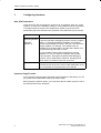
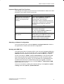
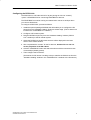
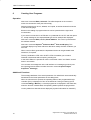
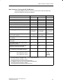
Supplement to the STEP 7 User Manual V4.0
New Functions in Version 4.02
C79000-Z7076-C552-01
Contents
Page
1
Overview
2
2
Creating and Editing Projects
3
3
Configuring Hardware
4
4
Configuring Networks and Connections
10
5
Using Upper and Lower Case for Shared
and Local Symbols
11
6
Creating User Programs
14
7
Displaying Reference Data
15
8
Creating and Displaying Messages
15
9
Debugging User Programs
16
10 Diagnosing Hardware
18
11 Archiving
18
12 Printing
19
Copyright 1998 by Siemens AG
C79000-Z7076-C552-01
New Functions in Version V4.02
1
Overview
New and Modified Functions in STEP 7 Version 4.02
The information in this supplement will familiarize you with the additional functions
of STEP 7, version 4.02 in a short and concise manner.
You should already be familiar with version 4.01 of the STEP 7 software and the
manual package “STEP 7 Basic Information V4.0” (Order Number
6ES7 810-4CA03-8BA0) supplied with it.
This supplement is structured in a similar way to the STEP 7 User Manual. First,
you will find details of the most important updates/changes in creating and editing
projects; then, information on configuring hardware, networks, and connections;
and finally, notes on creating and debugging user programs.
Minor changes are not documented here. If, for example, dialog boxes have been
changed, these changes are explained in the online help.
2
Supplement to the STEP 7 User Manual V4.0
C79000-Z7076-C552-01
New Functions in Version V4.02
2
Creating and Editing Projects
New Function: Password Protection for Access to Programmable Controllers
With the aid of password protection you can:
Protect the user program and its data in the CPU against unwanted changes
(write protection),
Protect the know-how in your user program (read protection),
Inhibit online functions which would interfere with the process.
You can only assign a password to a module if the module supports this function.
If you want to protect a module with a password, you must define the level of
protection and the password in the module parameter assignment, and then
download the modified parameters to the module (see Chapter 3, New CPU
Parameters).
If a password is required before an online function can be executed, the dialog box
“Enter Password” is displayed. By entering the correct password you are
authorized to access modules which have been assigned parameters specifying a
special level of protection. You can then establish online connections to the
protected module and execute the online functions which have been protected.
You can use the menu command PLC Access Rights to open the “Enter
Password” dialog box directly. Here you can specify that the password entered
should be used for all future access to protected modules. The dialog box will then
only appear if this password is invalid.
Additional Settings in the SIMATIC Manager
The tabbed dialog box which you open with the menu command Options Customize has been expanded and restructured. For example, you can now
select a “Quick View” when diagnosing hardware (see Chapter 10).
Supplement to the STEP 7 User Manual V4.0
C79000-Z7076-C552-01
3
New Functions in Version V4.02
3
Configuring Hardware
New CPU Parameters
There are many new components in version 4.02; for example, racks, C7 control
systems, or CPUs in the hardware catalog. It is not possible to list all the updates
or changes within the scope of this supplement; instead, only the new CPU
parameters (which are relevant to the operation of the latest CPUs) are covered:
CPU Parameter
Remarks
Test operation/
process operation
(see also
Chapter 9)
Can be set in the “Protection” tab.
In process operation, debugging functions such as “program
status” or “monitoring/modifying variables” are limited to
prevent the permissible increase in the scan cycle time from
being exceeded. For example, call conditions are not
permitted in the program status, and the status display for a
programmed loop is aborted on return.
It is not possible to debug with breakpoints in process
operation, nor can you execute a program step-by-step.
In test operation, all programming device/PC debugging
functions can be used without restriction, including those
which result in increases in the scan cycle time.
Protection level
Can be set in the “Protection” tab. Write access, and read
and write access to the CPU can be made dependent on the
use of a password. The password is set in this tab.
Improved Copy Function1
If you hold the CTRL key down and select several modules or DP slaves, you can
then paste these modules/DP slaves at another location.
Before pasting copied DP slaves, you must select the DP master system to which
the DP slaves are to be “attached.”
4
Supplement to the STEP 7 User Manual V4.0
C79000-Z7076-C552-01
New Functions in Version V4.02
Improved Display and Print Functions
The changes to the display and print functions are listed below in detail, with a brief
description of how each function can be used.
Function
Comment
Object names, for example, the
description of a CPU can be
stored in the programmable
controller.
Menu command Options Customize;
Option “Save Object Names in the
Programmable Logic Controller.”
These object names are displayed when the
configuration is uploaded to the programming
device and during diagnosis (improved
overview).
Print preview possible
Menu command Station Print Preview
Address list can be printed
Menu command View Address Overview;
then click the “Print” button
Or, menu command Station Print; then
select the “Address List” option.
Information on DDB files used is
also printed
When the station configuration is printed,
details relating to the DDB file for each of the
DP slaves are also printed; for example,
revision, revision number, DDB revision,
firmware release, hardware release.
Switching to Network Configuration
You can use the new menu command Options Configure Network to switch to
the application for network and connection configurations.
Working with DDB Files
The original procedure for supplying STEP 7 with new device database (DDB) files
has been improved. You can now use the menu command Options Install New
DDB Files and the subsequent dialog boxes to locate the DDB file you require.
Another new feature in STEP 7, version 4.02 and above, is that type files (DDB
files (.GSD)) and DP slave symbols (bitmaps) are now also stored in a project.
When you configure a new station, you can refer back to the type/DDB files and
symbols which were used to create another project (for example, on another
programming device). The new menu command Options Import Station DDB
Files enables you to do this.
The menu command for updating the hardware catalog is now Options Update
Catalog, rather than Options Update DDB Files.
Supplement to the STEP 7 User Manual V4.0
C79000-Z7076-C552-01
5
New Functions in Version V4.02
Configuring the ET 200X (BM 147/CPU) as a DP Slave
The BM 147/CPU basic submodule is configured as an intelligent DP slave. In
contrast to other intelligent DP slaves, the basic submodule can be found under
“PROFIBUS DP/ET 200X/BM 147/CPU” in the “Hardware Catalog” window.
Requirement: The application “Configuring Hardware” must be running.
Proceed as follows:
1. Configure the DP slave ET 200X (with BM 147/CPU) as an S7-300 station.
– Create a new station of the type S7-300 (menu command Station New).
– Select the “PROFIBUS DP/ET 200X/BM 147/CPU” directory in the
“Hardware Catalog” window.
– Copy the object “BM 147/CPU” to the empty station window using drag &
drop.
A configuration table is created for BM 147/CPU.
– Configure the DP slave with the required I/O expansion modules.
– Save the station (the intelligent DP slave).
2. In another station, configure a DP master (CPU with integrated PROFIBUS-DP
interface or CP with PROFIBUS-DP interface; only the latest CP 342-5
(342-5DA01-0XE0)).
3. Using drag & drop, copy the DP slave ET 200X (with BM 147/CPU) from the
“Hardware Catalog” window (Configured Stations container) to the symbol for
the DP master system.
4. Double-click the symbol for the intelligent DP slave and select the “Link” tab. In
this tab you can specify which station is to represent the intelligent DP slave.
5. Select the intelligent DP slave and click the “Link” button.
6. Select the “Slave Configuration” tab and assign the master and slave addresses
to one another.
7. Confirm the settings with “OK.”
6
Supplement to the STEP 7 User Manual V4.0
C79000-Z7076-C552-01
New Functions in Version V4.02
Configuring the DP/PA Link
The DP/PA link is a DP slave which for its part (acting as a kind of “master”)
“opens” a PROFIBUS PA for connecting PROFIBUS PA devices.
The PROFIBUS PA must be running at a transmission rate of 45.45 Kbps when
you connect PA devices.
To configure a DP/PA link, proceed as follows:
1. Install the optional package SIPROM; this will enable you to configure the PA
slaves from the “Hardware Catalog” window at a later stage. (The PA slaves are
located in the “PROFIBUS PA” container.)
2. Configure a DP master system.
3. Drag the DP/PA link (IM 157) from the “Hardware Catalog” window (“DP/PA
Link” container) to the DP master system.
4. Select the DP/PA link; the DP slave structure will be displayed in the lower
section of the station window.
5. Slot 4 represents the “master” for the PA devices; double-click on slot 4 to
set the properties of the PA subnet.
6. Click the “PROFIBUS” button and select the subnet with the transmission rate
of 45.45 Kbps (already preset).
7. Then configure the PA devices.
(Proceed as for DP slaves: Use drag & drop to transfer the PA devices from the
“Hardware Catalog” window in the “PROFIBUS PA” container to the PA subnet.)
Supplement to the STEP 7 User Manual V4.0
C79000-Z7076-C552-01
7
New Functions in Version V4.02
Configuring Software Redundancy
The configuration of a “warm standby” system consists of:
Two S7 stations with one PROFIBUS-DP master interface each (each of these
interfaces forms its own subnet).
One or more ET 200M devices with IM 153-3 which are connected to both
subnets.
This configuration ensures that the “standby station” takes over the processing of
the user program if one station (one of the two DP masters fails) fails.
Two stations, each with one PROFIBUS-DP master interface
Station A
Station B
ET 200 M with IM 153-3
DP Master 1
DP Master 2
PROFIBUS
To set up this configuration with STEP 7, proceed as follows:
1. Configure the first station (station A) with all the ET 200M devices (IM 153-3).
2. Configure the second station (station B) without I/Os.
3. Copy the ET 200M in station A and paste these DP slaves in the DP master
system of station B (menu command Edit Redundant Paste); see also
Page 4 (Improved Copy Function).
In contrast to the “normal” Paste function, “Redundant Paste” preserves the
existing PROFIBUS and I/O addresses. Inconsistencies in addresses are thus
avoided. You should follow step 3 very carefully; if the addresses overlap, this
may cause the “Redundant Paste” to fail.
4. Complete the configuration of station B with central and distributed I/Os.
Important: The DP slaves with IM 153-3 must be configured in each of the two
stations, which means they appear as two separate objects, although they are
physically one and the same slave. If you change settings for one of the DP
slaves, you must also copy this modified DP slave to the other station again to
ensure consistency.
8
Supplement to the STEP 7 User Manual V4.0
C79000-Z7076-C552-01
New Functions in Version V4.02
Creating a Catalog Profile
If the hardware catalog supplied with STEP 7 is too large or too difficult for you to
use, you can create your “own” catalog. In this way different catalog profiles are
produced. The basis for each new catalog profile is the modules/components
catalog with which you are already familiar. The profile of this catalog is known as
“standard;” you are free to assign names of your own choice to the catalog profiles
you create.
To create a new catalog profile, proceed as follows:
1. Select the menu command Options Edit Catalog Profiles.
The application is opened with two catalog profiles: the “Standard” profile and
an “empty” profile containing no components.
2. Drag the required folders and modules from the standard profile window and
drop them in the “empty” profile window. You can also adapt the structure to
meet your requirements using the menu command Insert New Folder.
3. Save the new catalog profile using the menu command File Save As; choose
a suitable name for the new profile.
The name of the new profile then appears in the “Profile” list box in the
“Hardware Catalog” window and can be selected.
Docking the “Hardware Catalog” Window on the Side of the Application Window
To prevent the “Hardware Catalog” window from obscuring the contents of the
station window, you can “dock” it on one side of the application window. Simply
double-click on the area above the “Profile” list box in the “Hardware Catalog”
window. To release the “docked” window, double-click on this area again.
You can change the size of the “Hardware Catalog” window when it is in the
“undocked” state.
A More Convenient Way to Download Hardware Configurations
If you select the function PLC Download and follow the dialog boxes, you can
execute the following actions with a programming device:
Switch the CPU to STOP mode
(if the mode selector is set to RUN-P)
Compress memory
(if insufficient contiguous free memory is available)
Set the CPU to RUN
Supplement to the STEP 7 User Manual V4.0
C79000-Z7076-C552-01
9
New Functions in Version V4.02
4
Configuring Networks and Connections
Configuring Connections while Configuring a Network
The application for configuring networks can also be used to configure
connections.
To configure a connection, simply select a module to which connection data can be
downloaded, for example, a CPU. The connection table for the selected module
will appear in the lower section of the network view.
Improved Display and Print Functions
The changes to the display and print functions are listed below in detail, with a brief
description of how each function can be used.
Function
10
Comment
MPI and PROFIBUS addresses
can be shown in the network
view.
Menu command Options Customize;
“Display Addresses” option.
Pagination for printing can be
shown in the network view.
Menu command Options Customize;
“Display Page Numbers” option.
More than one PROFIBUS
profile can be printed at a time.
Select the desired subnet, then print.
You can call up help on
messages (relating to the
configuration of connections) in
the “Warnings” window.
Double-clicking the message selects the
corresponding object in the network view.
You can print out any errors
which occur during the
compilation of connections.
Menu command Options Customize;
“Print/Networks/Errors” option.
To prevent the “Catalog” window
from obscuring the contents of
the network view, you can “dock”
it on the side of the network
view. You can change the size of
the window when it is in the
non-docked position.
Double-click the upper section of the
“Catalog” window to toggle between the
docked and non-docked position.
Supplement to the STEP 7 User Manual V4.0
C79000-Z7076-C552-01
New Functions in Version V4.02
Connecting an S7-200 to the Multipoint Interface
If you wish to connect an S7-200 to the MPI subnet (in addition to programming
devices, operating panels, or S7-300/400s), you must select a transmission rate of
19.2 Kbps in the properties dialog box for the MPI subnet.
The following restrictions apply:
A maximum of 8 nodes are permitted
(CPUs, programming devices/operator panels, communications processors/
function modules with separate MPI addresses (each node must be able to
support 19.2 Kbps)).
5
Global data communication between these nodes is impossible.
Only certain S7-200 devices can be connected (see S7-200 System Manual).
Using Upper and Lower Case for Shared and Local Symbols
No Distinction Between Upper and Lower Case Characters
In previous versions of STEP 7, the user could define symbols which differed from
one another only in the case used for individual characters. This has been changed
in STEP 7, V4.02. From this version onwards, it will no longer be possible to
distinguish between symbols created in upper and lower case.
This change was made in response to the wishes of our customers, and will greatly
reduce the risk of errors occurring in a program. The restrictions which have been
made to the symbol definition also support the aims of the PLCopen forum to
define a standard for transferable programs.
A symbol definition based solely on the distinction between upper and lower case
characters is now no longer supported. For example, in previous versions the
following definition was possible in the symbol table:
Motor1 = I 0.0
motor1 = I 1.0
The symbols were distinguished on the basis of the case of the first letter. This
type of differentiation carries with it a significant risk of confusion. The new
definition eliminates this possible source of errors.
Supplement to the STEP 7 User Manual V4.0
C79000-Z7076-C552-01
11
New Functions in Version V4.02
Effects on Existing Programs
If you have been using this criterion to distinguish between different symbols, you
may experience difficulties with the new definition if:
Symbols differ from one another only in their use of upper and lower case
characters
Parameters differ from one another only in their use of upper and lower case
characters
Symbols differ from parameters only in their use of upper and lower case
characters
All three of these conflicts can, however, be analyzed and resolved as described
below.
Symbols which Differ from One Another Only in their Use of Upper and Lower
Case Characters
Conflict:
If the symbol table has not yet been edited with the current version of the software,
the first of the non-unique symbols in the table is used when source files are
compiled.
If the symbol table has already been edited, such symbols are invalid; this means
that the symbols are not displayed when blocks are opened and source files
containing these symbols can no longer be compiled without errors.
Remedy:
Check your symbol table for conflicts by opening the table and saving it again. This
action enables the program to recognize the non-unique symbols. You can then
display the non-unique symbols using the filter “Non-Unique Symbols” and correct
them. You should also correct any source files which contain conflicts. You do not
need to make any further changes to the blocks, as the current (now conflict-free)
version of the symbol table is automatically used or displayed when a block is
opened.
12
Supplement to the STEP 7 User Manual V4.0
C79000-Z7076-C552-01
New Functions in Version V4.02
Parameters which Differ from One Another Only in their Use of Upper and Lower
Case Characters
Conflict:
Source files containing such interfaces can no longer be compiled without errors.
Blocks with such interfaces can be opened, but access to the second of these
parameters is no longer possible. When you try to access the second parameter,
the program automatically returns to the first parameter when the block is saved.
Remedy:
To check which blocks contain such conflicts, it is advisable to generate a source
file for all the blocks of a program using the function “Generate Source File.” If
errors occur when you attempt to compile the source file you have created, a
conflict is present.
Correct your source files by ensuring that the parameters are unique; for example,
using the Search/Replace function. Then compile the files again.
Symbols which Differ from Parameters Only in their Use of Upper and Lower
Case Characters
Conflict:
If shared and local symbols in a source file only differ from one another in their
upper and lower case characters, and if no initial characters have been used to
identify shared (“symbol name”) or local (#symbol name) symbols, the local symbol
will always be used during compilation. This will cause the machine code to be
modified.
Remedy:
In this case it is advisable to generate a new source file from all of the blocks. This
will automatically assign local and shared access with the corresponding initial
characters and will ensure that they are handled correctly during future compilation
procedures.
Supplement to the STEP 7 User Manual V4.0
C79000-Z7076-C552-01
13
New Functions in Version V4.02
6
Creating User Programs
Operation
New menu command Edit Select All: The effect depends on the context in
which the command is used (see online help).
Selected networks can be cut, deleted, and copied, as well as inserted into blocks
of the same language.
Blocks in the catalog of program elements can be opened with the right-hand
mouse button.
If you select a connection in an FBD box or a parameter line in STL and then press
F1, a help message on the expected data type and an example are displayed.
New menu command Edit Go To Block Address: The cursor is positioned at
the address entered.
New menu command Options Reference Data Filter and Display: This
command displays only those reference data which satisfy the filter conditions you
have set.
When a source file is generated, the dependent blocks can be generated at the
same time, if required.
The key combination CTRL+W or SHIFT+CTRL+W enables you to search
forwards or backwards without opening a dialog box.
In the ASCII Editor it is possible to use the commands “Undo” and “Redo” several
times in succession.
You can enter a message text at the call interface of a message-type block (use
the right-hand mouse button to select the menu command Special Object
Properties Message).
Additional Functions
The message attributes of the actual parameter of a called block are automatically
transferred to the formal parameters of the calling block.
When an online block is opened, the operating status of the programmable logic
controller (PLC) is displayed in color in the status bar. During monitoring (menu
command Debug Monitor), a colored progress bar is displayed in the status bar;
when the function is deactivated, the operating status replaces the progress bar.
Local symbols from data blocks are displayed (“Symbol information for data bits”).
14
Supplement to the STEP 7 User Manual V4.0
C79000-Z7076-C552-01
New Functions in Version V4.02
7
Displaying Reference Data
New Menu Command: Filter and Display
You can use this menu command to call up the reference data and to set the filters
before the reference data are displayed. If a program is very large, you can use
filters to limit the quantity of data to be displayed. This enables you to obtain the
information you require more quickly.
8
Creating and Displaying Messages
Assigning Value Ranges for Message Numbers
Messages are identified by a number which is unique throughout a project. Each
individual S7 program is assigned a number range within the whole range of
numbers available (1 – 2097151). If you copy a program, the new program must be
assigned a new number range.
The menu command Edit Special Object Properties Message Numbers
opens the dialog box in which you can select the number range for the new
program. The dialog box shows the number ranges which have already been
allocated and the respective programs to which they have been assigned. These
ranges cannot be used again. The dialog box is also displayed when you copy or
insert programs into a project and the number ranges overlap.
If you want to change the number range for a program, proceed as follows:
1. Copy the program.
2. Insert the program in the project again and assign it a new number range.
Background: A number range can only be assigned to a program containing no
messages. If messages are already present, you must copy the program and
assign it a new number range.
Tip: To avoid having to renumber a program later on, you should check the
number range first before you create any messages.
Printing Messages
Menu command File Print Messages, see Chapter 12 (Printing).
Supplement to the STEP 7 User Manual V4.0
C79000-Z7076-C552-01
15
New Functions in Version V4.02
9
Debugging User Programs
Programming LAD/STL/FBD S7 Blocks: Test Environment for Debugging in
Program Status
The execution of test functions is dependent on the mode of operation set (process
operation or test operation). The mode determines whether test functions are
permitted and determines the increase in the scan cycle time caused by test
functions.
“Process operation”: test functions restricted (see Chapter 3, new CPU
parameters).
“Test operation”: all test functions can be used without restriction; greater
increases in the CPU scan cycle time are possible.
You must be in “test operation” before you can set breakpoints and execute the
program step-by-step.
You can use the menu command Debug Operation to display the mode of
operation set. The following situations may arise:
The settings cannot be changed in the dialog box. You must change the
relevant CPU parameters in the “Protection” tab.
The settings can be changed in the dialog box. In this case, you can set the
required mode of operation in the dialog box (in other words, the mode cannot
be set for the CPU).
Debugging in Program Status: Procedure
Blocks programmed in STL, FBD, or LAD can only be debugged online in program
status. The block must be available online. Proceed as follows:
1. If necessary, select the menu command File Open to open the logic block to
be tested and display it in a window.
2. (Optional) Select the menu command Debug Call Environment and set the
trigger conditions in the dialog box displayed. The program status is then only
recorded if the set conditions occur.
3. Use the menu command Debug Operation to display the test environment
which has been set. If the mode of operation was selected when parameters
were assigned to the CPU, you can only change the mode by modifying the
parameters. If not, you can change the mode in the dialog box (test operation /
process operation).
4. Open the “Customize” dialog box using the menu command Options Customize In the “STL” tab or “LAD/FBD” tab, select which information should
be displayed in the program status.
5. Start the recording of the program status using the menu command Debug Monitor (check mark in front of the menu command).
The STL program status is displayed in the form of a table in the code section of
the block. You can deactivate the display by selecting the menu command Debug
Monitor again.
16
Supplement to the STEP 7 User Manual V4.0
C79000-Z7076-C552-01
New Functions in Version V4.02
New Functions: Forcing with S7-300 Modules
The following table provides an overview of the functions and summarizes the
differences between forcing and modifying.
Force
Feature / Function
with S7-400
Modify
with S7-300
Bit memory (M)
yes
no
yes
Timers and counters (T, C)
no
no
yes
Data blocks (DB)
no
no
yes
Peripheral inputs (PIB, PIW, PID)
yes
no
no
Peripheral outputs (PQB, PQW, PQD)
yes
yes *
yes
Inputs and outputs (I, Q)
yes
yes *
yes
Defining triggers
always trigger
immediately
always trigger
immediately
yes
(once or every
cycle)
Function only affects variable in visible
area of active window.
affects all
force values
affects all
force values
yes
User program can overwrite the modify/
force values.
no
yes *
yes
Replacing the force value effective without
interruption.
yes
yes
no
The variables retain their values when
application is exited.
yes
yes
no
Variables retain their values after the
connection to the CPU is broken.
yes
yes
no
Variables retain their values after power
off, provided CPU has battery backup.
yes
yes
no
Address error permitted:
e.g.:
IW1 modify/force value: 1
IW1 modify/force value: 0
no
no
yes
the last
becomes
effective
* The inputs (process-image input table) occupied by force values can be overwritten with:
- write instructions (for example, T IB x; = I x.y; copying with SFCs)
- read instructions (for example, L PIW x)
- write programming device/operator panel functions
The outputs occupied by force values can be overwritten with:
- write instructions (for example, T PQB x)
- write programming device/operator panel functions
Supplement to the STEP 7 User Manual V4.0
C79000-Z7076-C552-01
17
New Functions in Version V4.02
10
Diagnosing Hardware
New Function: Diagnosing Hardware – Quick View
In the SIMATIC Manager you can specify which of the following options should be
displayed when you call up diagnosing hardware:
Short information (“Diagnosing Hardware - Quick View” dialog box) or
Detailed information (“HW Config - Diagnosing Hardware” dialog box)
In the second case, it takes STEP 7 longer to trace and display the data.
1. Select the menu command Options Customize in the SIMATIC Manager.
2. Activate (default setting) or deactivate the option “Display Quick View when
Diagnosing Hardware” in the “View” tab of the dialog box.
The quick view only displays the CPU and those modules in which the CPU has
detected a fault (for example, diagnostic interrupt, I/O access error). You can
select a module and then call up the module status. This will provide you with
detailed diagnostic information, depending on the diagnostic capability of the
module.
You can use the “Open Station Online” button to display the diagnostic information
in its entirety. This provides you with a graphic overview of the whole station, as
well as information on the configuration.
11
Archiving
Support for Archive Program JAR (1.02) and Winzip (Batch Mode)
If you wish to archive files, you can now also use the JAR archive program
(version 1.02 onwards) or the WinZip archive program (version 6.3 onwards) in
batch mode.
Archiving Projects with “Long” File Names
Projects which have long file names (beyond the 8.3 DOS convention) or deeplynested directory structures (with directories whose absolute path name exceeds 64
characters) should only be archived using the WinZip or JAR archive programs.
Using other archive programs does not guarantee that you will be able to unpack
the archive files in these structures completely or correctly. This applies in
particular to projects containing objects from the WinCC optional package.
18
Supplement to the STEP 7 User Manual V4.0
C79000-Z7076-C552-01
New Functions in Version V4.02
12
Printing
Improved Print Functions in the SIMATIC Manager
You can use the menu command File Print Object List to print a list of the
selected objects on the default printer. The list contains the object information
which is displayed in the “Details” view of the SIMATIC Manager.
You can use the menu command File Print Messages to print messages
belonging to individual objects. You can use the filters in the dialog box to select
which types of messages you want to print. This is particularly important if you
have selected a project or program that contains many different messages. All the
messages below the selected object are printed.
You can use the menu command File Print Object to print the selected object
on the default printer.
Supplement to the STEP 7 User Manual V4.0
C79000-Z7076-C552-01
19
New Functions in Version V4.02
20
Supplement to the STEP 7 User Manual V4.0
C79000-Z7076-C552-01