1
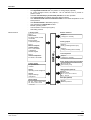
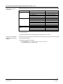
7
865
RWF40... complete with housing
Compact
Universal Controllers
RWF40...
The RWF40... is a universal digital boiler temperature / pressure controller with
functions designed specifically for the control of heat generating plant.
The RWF40... and this Data Sheet are intended for use by OEMs which integrate
the controller in their products!
Mechanical design
The controller is supplied complete with housing for flush panel mounting. The
RWF40... is matched to the controlled variable and the required setpoint range by making parameter settings. The control parameters can be set and optimized while the
burner is running. All settings are made with 4 buttons located on the unit front and are
directly displayed.
LEDs on the front indicate the following operating states:
Control ON / OFF
Positioning pulses ON or OFF for driving the burner´s air damper when using
modulating burner control, or stage I / stage II when using 2-stage burner control
«2-stage» operating mode
Position of the configurable contact «K6»
Manual control ON / OFF
During operation, the digital display above the LEDs shows the setpoint (green), the
actual value (red) and – when making parameter settings – the relevant parameters.
CC1N7865en
01.09.2005
Building Technologies
HVAC Products
Warning notes
To avoid injury to persons, damage to property or the environment, the following
warning notes should be observed!
Do not open, interfere with or modify the controller!
•
•
•
•
•
All activities (mounting, installation and service work, etc.) must be performed by
qualified staff
When selecting the cables, when making the installation and the electrical connections, observe the regulations of VDE 0100 «Erection of power installations with
rated voltages below AC 1000 V» and the relevant national regulations
Provide double-pole isolation of the controller from the mains supply if there is a
risk of touching live parts while work is carried out
Check to ensure that wiring is in an orderly state
Fall or shock can adversely affect the safety functions. Such units must not be put
into operation, even if they do not exhibit any damage
Mounting notes
•
Ensure that the relevant national safety regulations are complied with
•
Please observe the notes given in the user documentation B7865
•
Prior to commissioning the plant, check to ensure that wiring is in an orderly state
Installation notes
Commissioning notes
Standards and certificates
Conformity to EEC directives
- Electromagnetic compatibility EMC (immunity) 89 / 336 EEC
NE21, EN 50 081 part 1
- Electromagnetic compatibility EMC
and EN 50 082 part 2
NAMUR recommentation
ISO 9001: 2000
Cert. 00739
ISO 14001: 1996
Cert. 38233
Service notes
•
•
•
For service purposes, the controller can be removed from its housing with no need
for tools
The electrical connections are made via the screw terminals located at the rear of
the housing
Each time a unit has been replaced, check to ensure that wiring is in an orderly
state and that the wires are firmly connected
Disposal notes
The unit contains electrical and electronic components and must not be disposed of
together with household waste.
Local and currently valid legislation must be observed.
2/10
Building Technologies
HVAC Products
CC1N7865en
01.09.2005
Type summary
Controller with
3-position output
housing
fixing material and seal
RWF40.000A97
Controller with
3-position output
analog output
housing
fixing material and seal
RWF40.001A97
Controller with
3-position output
analog output
RS-485 port
housing
fixing material and seal
RWF40.002B97
Packaging variants (20 pieces, without documentation)
RWF40.010A97
RWF40.011A97
Accessories
Adapter frame for replacing the RWF32...
Bracket
For mounting the RWF40... on 35 mm DIN rails to DIN 46277
Dummy cover
For covering a panel cutout for the RWF40...
Demo case
For demonstrating the functions of the RWF40... controller
ARG40
ARG41
AVA10.200/109
KF8892
3/10
Building Technologies
HVAC Products
CC1N7865en
01.09.2005
Technical data
General controller data
Environmental
conditions
Mains voltage
Mains frequency
Safety class
Mounting position
Terminals for
Power consumption
Safety extra low-voltage
Contact rating of the control outputs
(relays «K1...K3»)
Up to 2 x 10⁵ switching cycles
Up to 107 switching cycles
Weight complete with housing
Recommended actuator running time
Degree of protection of housing
Front
Base
AC 110...240 V +10 % / -10 %
48...63 Hz
II to DIN 0631
optional
2 x 1.5 mm² or 1 x 2.5 mm²
max. 10 VA
DC 24 V
Storage
Temperature range
Humidity
Transport
Temperature range
Humidity
Operation
Temperature range
Humidity
DIN EN 60 721-3-1
-20...+60 °C
< 75 % r.h.
2 A / AC 24...240 V
0.1 A / AC 24...240 V
approx. 760 g
15...60 s
IP 65, EN 60529
IP 20, EN 60529
-40...+70 °C
< 75 % r.h.
-20...+50 °C
< 75 % r.h.
Condensation, formation of ice and ingress of water are not permitted!
4/10
Building Technologies
HVAC Products
CC1N7865en
01.09.2005
Function
The RWF40... provides the following functions:
One digital PID controller with a 3-position or analog output (optional)
To control 2-stage burners, the RWF40... can be switched over to provide 2position control
Automatic thermostat (or pressurestat) function in low-fire operation
One shift controller for weather-dependent setpoint shifting
One minimum limiter and one maximum limiter for the boiler temperature or the
boiler pressure
One limit thermostat to DIN 3440 (output 1)
One potential-free configurable contact
Manual operating mode
Communication via serial port (option)
Self-setting function
Block structure
3 analog inputs
Release of burner
Input 1:
Actual value
for Pt100, Ni100, Pt1000,
LG-Ni1000,
thermocouples
or standard signals
Input 3:
Outside temperature
for Pt1000, LG-Ni1000
2 binary inputs
For potential-free
contacts
Input 1:
Operating mode changeover
Input 2:
Setpoint shifting /
changeover
Floating output
Output 2:
-Relay (actuating device open)
Output 3:
- Relay (actuating device closed)
RWF40...
Input 2:
External setpoint,
setpoint shifting
for 0...1 kΩ resistor
or linearized
standard signals
Output 1:
- Relay (N.O. contact)
Limit comparator
Output 4:
- Relay (N.O. contact)
Power supply measuring transducer
DC 24 V, 30 mA
(short-circuit proof)
Analog output (optional)
Output 5:
Analog output
DC 0...10 V, DC 0...20 mA,
DC 4...20 mA
Serial port (optional)
Power supply
AC 110 ...240 V +10%/-10%,
48...63 Hz, max. 10 VA
RS-485
MOD bus protocol
7865f01e/0905
5/10
Building Technologies
HVAC Products
CC1N7865en
01.09.2005
Function of the controller when used for burner control
Low-fire operation
In low-fire operation, the RWF40... operates like a control thermostat or pressurestat.
This means that it operates as a 2-position controller maintaining the required setpoint
by switching the burner on and off. The switching differential for 2-position operation
can be adjusted within a wide range. If the demand for heat increases, the controller
switches to high-fire operation only when an adjustable limit is exceeded. This function
is aimed at optimizing the burner´s switching ratio.
High-fire operation,
2-stage control
In that case, the RWF40... operates as a 2-position controller with adjustable switching
thresholds. Using the relays of the 3-position output, the RWF40... drives the actuator
to the 1st and 2nd output stage. In this operating mode, the optional analog output
switches between the minimum signal for the 1st stage and the maximum output signal
for the 2nd stage.
High-fire operation,
modulating control
In that case, the RWF40... operates as a PID / PI controller with a 3-position output
without position feedback signals or, optionally, with a modulating output. By making
use of its self-setting facility, the RWF40... is able to determine the PID / PI control
parameters, or the parameters can be set manually.
Binary input 1 (changeover of operating mode)
Using a potential-free contact, the RWF40... can be switched from the modulating
mode to 2-stage operation.
Binary input 2 (setpoint
shifting or setpoint
changeover)
In the case «setpoint shifting» is configured, the current setpoint is shifted by an adjustable amount. Configuration of «setpoint changeover» provides changeover between 2
setpoints adjusted on the RWF40... If analog input 2 is configured for an «external setpoint», changeover is provided between the setpoint adjusted on the RWF40... and an
external setpoint.
Limit comparator
Potential-free contact «K6» can be assigned a number of functions.
Example: Limit value supervision
Operation
4 buttons on the unit front are used to operate and program the RWF40... During operation and programming, the 7-segment displays show the parameter values and parameter names.
Weather-dependent
setpoint shifting
The controller´s standard configuration ex works is such that when connecting a
QAC22… outside sensor, automatic changeover to weather-dependent setpoint shifting
takes place.
The signal delivered by the QAC2... outside sensor must not be fed parallel to several RWF40...!
6/10
Building Technologies
HVAC Products
CC1N7865en
01.09.2005
Function of the controller when used for burner control (cont´d)
Analog input 1 (actual
value sensor)
To acquire the actual value, a number of sensors can be connected to the RWF40...
Measurement range
2-or 3-wire resistance
sensors
Thermocouples
Linearized standard
signals
Pt100 / IEC 751
-200...+850 °C (-328...+1562 °F)
Pt1000 / IEC 751
-200...+850 °C (-328...+1562 °F)
Ni100 / DIN 43760
-60...+230 °C (-76...+482 °F)
Ni1000 / DIN 43760
-60...+230 °C (-76...+482 °F)
LG-Ni1000
-50...+160 °C (-58...+320 °F)
NiCr-Ni / type «K»
-200...+1372 °C (-328...+2502 °F)
Cu-Cu-Ni / type «T»
-200...+400 °C (-328...+752 °F)
NiCroSil-NiSil / type «N»
-100...+1300 °C (-148...+2372 °F)
FeCuNi / type «J»
-200...+1000 °C (-328...+1832 °F)
Pt-RhPt / type «S»
0...1768 °C (-32...3214 °F) ¹)
Pt-RhPt / type «R»
0...1768 °C (-32...3214 °F) ¹)
Pt-RhPt / type «B»
0...1820 °C (32...3308 °F) ¹)
0...20 mA
scalable -1999...+9999
4...20 mA
scalable -1999...+9999
DC 0...10 V
scalable -1999...+9999
DC 0...1 V
scalable -1999...+9999
¹) Only RWF40.0X2B97
The power provided for the measuring transducers is DC 24 V / 30 mA.
Analog input 2 (external
setpoint shift or external
setpoint)
Feeding a signal to analog input 2, the controller´s setpoint can be influenced. The
influence can be scaled.
The following signals can be used:
Input signals DC 0...1 V, DC 0...10 V, 0...20 mA, 4...20 mA
1 kΩ potentiometer in a 2-wire circuit
7/10
Building Technologies
HVAC Products
CC1N7865en
01.09.2005
Connection diagram (basic diagram)
Temperature and pressure control on a dual-fuel burner.
Burner control and supervision are provided by burner control type LAL... or LFL...
Note
DC 24 V at terminals «G+» and «G-» is used for powering the QBE... pressure sensor!
RWF40...
L N G1+ M1 B9
M9 XB6 M6
Q13 Q14
Y2 Q D1 GND D2
Y1
LAL..., LFL...
4 5
ST
B
M
B
QAE...
M
int. ext.
19
18
9 11 10 20
S1
BS
102
QAC...
M
R
BV1
LK
BSG...
a
v
N
z
m
M
~
0
GAS
SQ...
MIN.
RV
BV1
I
BV2
OIL
L
N
7865a01/1004
RWF40...
L N
G+ U1- M1 G- XU6 M6 Q13 Q14
Y2 Q D1 GND D2
Y1
LAL..., LFL...
int. ext.
ST
G
B
19
18
4 5
9 11 10 20
S1
BS
M
102
QBE...
0...10 V
BV1
BSG...
N
LK
0
a
v
z
M
~
GAS
m
SQ...
MIN.
RV
BV1
I
BV2
OIL
L
N
7865a02/0905
Legend
a
Limit switch for air damper position OPEN
QAE...
BS
Operation selector
QBE...
Pressure sensor
1 = firing on gas
RV
Gas control damper
(modulating burner control)
S1
Internal / external setpoint switch (E)
2 = firing on oil
SQ...
(2-stage burner control)
BV...
Fuel valve
BSG...
Remote setpoint adjuster (active when
«S1» is closed)
L...
Burner control
LK
Burner´s air damper
m (MIN)
Auxiliary switch for controlling low-fire
operation
QAC...
Immersion temperature sensor
Actuator of burner´s air damper and gas
control damper
ST
Connections for burner control´s start
control loop
v
Auxiliary switch for the release of the
2nd fuel valve depending on the air damper
position
z
End switch for the fully CLOSED
position of the air damper
Outside sensor for weather-dependent
setpoint shifting
8/10
Building Technologies
HVAC Products
CC1N7865en
01.09.2005
Dimensions
PGM
96
K6
91,5
Dimensions in mm
48
EXIT
RWF40
112
43,5
Panel cutout to DIN 43 700
92 +0,8
7865m01e/0300
15,5
127,5
45 +0,6
ARG40 adapter frame
7865m02/0799
9/10
Building Technologies
HVAC Products
CC1N7865en
01.09.2005
Dimensions (cont´d)
Dimensions in mm
ARG41
83
10/10
Building Technologies
HVAC Products
7,5
13
61,4
45
68
60
3
35,5
45
8
94
153
12,5
7865m04/1004
© 2005 Siemens Building Technologies Production GmbH
Subject to change!
CC1N7865en
01.09.2005