1
SIRIUS Motor Starter
M200D AS-Interface Basic
Manual • 03/2009
SIRIUS
Answers for industry.
SIRIUS
Motor starter
M200D AS-Interface Basic
Introduction / product
description
1
Product family
2
Functions
3
Installation / connection
4
Configuration /
parameterization
5
Commissioning
6
Diagnostics
7
Technical specifications
8
Appendix
A
Manual
03/2009
A5E01668085-01
Legal information
Warning notice system
This manual contains notices you have to observe in order to ensure your personal safety, as well as to prevent
damage to property. The notices referring to your personal safety are highlighted in the manual by a safety alert
symbol, notices referring only to property damage have no safety alert symbol. These notices shown below are
graded according to the degree of danger.
DANGER
indicates that death or severe personal injury will result if proper precautions are not taken.
WARNING
indicates that death or severe personal injury may result if proper precautions are not taken.
CAUTION
with a safety alert symbol, indicates that minor personal injury can result if proper precautions are not taken.
CAUTION
without a safety alert symbol, indicates that property damage can result if proper precautions are not taken.
NOTICE
indicates that an unintended result or situation can occur if the corresponding information is not taken into
account.
If more than one degree of danger is present, the warning notice representing the highest degree of danger will
be used. A notice warning of injury to persons with a safety alert symbol may also include a warning relating to
property damage.
Qualified Personnel
The device/system may only be set up and used in conjunction with this documentation. Commissioning and
operation of a device/system may only be performed by qualified personnel. Within the context of the safety notes
in this documentation qualified persons are defined as persons who are authorized to commission, ground and
label devices, systems and circuits in accordance with established safety practices and standards.
Proper use of Siemens products
Note the following:
WARNING
Siemens products may only be used for the applications described in the catalog and in the relevant technical
documentation. If products and components from other manufacturers are used, these must be recommended
or approved by Siemens. Proper transport, storage, installation, assembly, commissioning, operation and
maintenance are required to ensure that the products operate safely and without any problems. The permissible
ambient conditions must be adhered to. The information in the relevant documentation must be observed.
Trademarks
All names identified by ® are registered trademarks of the Siemens AG. The remaining trademarks in this
publication may be trademarks whose use by third parties for their own purposes could violate the rights of the
owner.
Disclaimer of Liability
We have reviewed the contents of this publication to ensure consistency with the hardware and software
described. Since variance cannot be precluded entirely, we cannot guarantee full consistency. However, the
information in this publication is reviewed regularly and any necessary corrections are included in subsequent
editions.
Siemens AG
Industry Sector
Postfach 48 48
90026 NÜRNBERG
GERMANY
Ordernumber: 3RK1702-2BB11-1AA1
Ⓟ 03/2009
Copyright © Siemens AG 2009.
Technical data subject to change
Table of contents
1
2
3
Introduction / product description............................................................................................................... 9
1.1
What are M200D distributed motor starters?.................................................................................9
1.2
1.2.1
Fieldbus interfaces.......................................................................................................................11
AS-Interface .................................................................................................................................11
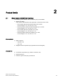
Product family.......................................................................................................................................... 13
2.1
Motor starter M200D AS-Interface ...............................................................................................13
2.2
Overview of the device functions .................................................................................................14
2.3
2.3.1
2.3.2
2.3.3
Design concept ............................................................................................................................15
Operator controls .........................................................................................................................16
Connections .................................................................................................................................17
Status indicators ..........................................................................................................................18
Functions ................................................................................................................................................. 19
3.1
Overview of the device functions .................................................................................................19
3.2
Introduction ..................................................................................................................................20
3.3
3.3.1
3.3.2
Basic functions / parameters........................................................................................................21
Rated operating current ...............................................................................................................21
Protection against voltage failure.................................................................................................21
3.4
Fieldbus interface.........................................................................................................................22
3.5
3.5.1
3.5.2
Motor control ................................................................................................................................23
Control function: reversing starter................................................................................................23
Brake output.................................................................................................................................23
3.6
3.6.1
3.6.2
Motor protection ...........................................................................................................................25
Thermal motor model...................................................................................................................25
Temperature sensor.....................................................................................................................27
3.7
3.7.1
3.7.2
3.7.3
3.7.4
3.7.5
3.7.5.1
3.7.5.2
System monitoring .......................................................................................................................29
Current limit values ......................................................................................................................29
Asymmetry monitoring .................................................................................................................31
Inputs ...........................................................................................................................................32
Outputs.........................................................................................................................................35
Connector monitoring...................................................................................................................36
Power connector ..........................................................................................................................36
Motor connector ...........................................................................................................................37
3.8
Short-circuit protection (circuit breaker / disconnecting means)..................................................38
3.9
3.9.1
3.9.2
3.9.3
Communication ............................................................................................................................38
Mode monitoring ..........................................................................................................................39
Plausibility check for settings .......................................................................................................39
Message output ...........................................................................................................................40
3.10
Trip reset ......................................................................................................................................41
3.11
Self-test ........................................................................................................................................41
M200D AS-Interface Basic
Manual, 03/2009, A5E01668085-01
5
Table of contents
4
5
6
7
6
3.12
Solid-state/mechanical switching technology.............................................................................. 42
3.13
Local device interface ................................................................................................................. 43
3.14
Integrated manual local control................................................................................................... 44
Installation / connection ........................................................................................................................... 47
4.1
4.1.1
4.1.2
4.1.3
4.1.4
4.1.5
4.1.6
Installation ................................................................................................................................... 47
Installation rules .......................................................................................................................... 47
Derating....................................................................................................................................... 48
Installing the protection guards ................................................................................................... 51
Installing the motor starter........................................................................................................... 52
Functional ground ....................................................................................................................... 52
Setting the AS-i address ............................................................................................................. 53
4.2
4.2.1
4.2.2
4.2.3
4.2.4
4.2.5
4.2.6
4.2.6.1
4.2.6.2
4.2.7
4.2.8
Connection .................................................................................................................................. 55
Required components/cables ..................................................................................................... 55
Prefabricating power cables........................................................................................................ 56
Installing and wiring power connectors ....................................................................................... 57
Power terminal ............................................................................................................................ 58
Brake output................................................................................................................................ 60
Digital inputs/outputs................................................................................................................... 62
Digital inputs................................................................................................................................ 62
Digital output ............................................................................................................................... 63
AS-Interface ................................................................................................................................ 64
Connection options for AS-Interface ........................................................................................... 64
Configuration / parameterization .............................................................................................................. 67
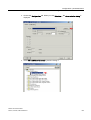
5.1
Configuration............................................................................................................................... 67
5.2
Configuration on the AS-i master CP 343-2................................................................................ 68
5.3
5.3.1
5.3.2
Parameterization ......................................................................................................................... 71
Parameterization ......................................................................................................................... 71
Parameterization via local setting ............................................................................................... 72
5.4
Process images........................................................................................................................... 74
Commissioning ........................................................................................................................................ 75
6.1
Prerequisites ............................................................................................................................... 75
6.2
M200D AS-i components ............................................................................................................ 76
6.3
Procedure.................................................................................................................................... 77
Diagnostics .............................................................................................................................................. 79
7.1
Diagnostics.................................................................................................................................. 79
7.2
7.2.1
7.2.2
Diagnostics with LED .................................................................................................................. 80
Statuses of the individual LEDs .................................................................................................. 80
LED display combinations........................................................................................................... 82
7.3
Diagnostics via parameter channel (parameter echo) ................................................................ 84
7.4
Diagnostics with the addressing and diagnostics unit ................................................................ 87
7.5
7.5.1
7.5.2
Troubleshooting .......................................................................................................................... 87
Response to faults ...................................................................................................................... 87
Acknowledging faults .................................................................................................................. 88
M200D AS-Interface Basic
Manual, 03/2009, A5E01668085-01
Table of contents
8
A
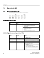
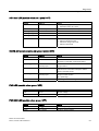
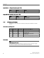
Technical specifications........................................................................................................................... 89
8.1
General technical specifications ..................................................................................................89
8.2
Motor starter.................................................................................................................................90
8.3
Brake control ................................................................................................................................91
8.4
Inputs ...........................................................................................................................................92
8.5
Output ..........................................................................................................................................92
8.6
Thermistor motor protection.........................................................................................................93
8.7
Switching frequency.....................................................................................................................93
8.8
Electrical service life of contactor.................................................................................................96
8.9
Dimension drawing ......................................................................................................................98
Appendix.................................................................................................................................................. 99
A.1
A.1.1
A.1.2
Order numbers .............................................................................................................................99
Order numbers .............................................................................................................................99
Spare parts/accessories ............................................................................................................100
A.2
Bibliography ...............................................................................................................................102
Glossary ................................................................................................................................................ 105
Index...................................................................................................................................................... 109
M200D AS-Interface Basic
Manual, 03/2009, A5E01668085-01
7
Table of contents
8
M200D AS-Interface Basic
Manual, 03/2009, A5E01668085-01
Introduction / product description
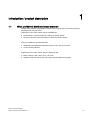
1.1
1
What are M200D distributed motor starters?
M200D motor starters are standalone devices with a high degree of protection (IP65) for
distributed use near the motor.
Depending on the order variant, they are available as:
● Direct starters, electromechanical or electronic (DSte, sDSte)
● Reversing starters, electromechanical or electronic (RSte, sRSte)
They are suitable for the following tasks:
● Switching and protecting three-phase loads at 400 V AC up to 5.5 kW
● Control via AS-Interface
Depending on the order variant, they are equipped with:
● Brake output for 400 / 230 V AC or 180 V DC
● Integrated manual local control with a key-operated switch and keypad
M200D AS-Interface Basic
Manual, 03/2009, A5E01668085-01
9
Introduction / product description
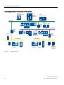
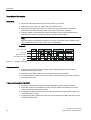
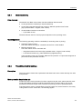
1.1 What are M200D distributed motor starters?
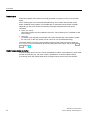
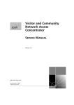
Connecting the M200D motor starter to AS-Interface
3&ZLWK
62)71(731,2
6
HJZLWK
&3
$GYDQFHG
6
HJZLWK&3
352),1(7
6
HJZLWK&3
*'
(7SUR
,(3%
/,1.
31,2
352),%86
,($6L
/,1.
31,2
3RZHU
VXSSO\XQLW
(76
$6,17(5)$&(
3*HJ
ZLWK&3
$6,17(5)$&(
6ODYH
0'
Figure 1-1
10
6ODYH
'3$6L
/,1.
$GYDQFHG
(7SUR
*'
0'
3RZH
U
VXSSO
\XQLW
6ODYH
6ODYH
6ODYHZLWK
(0(5*(1
&<6723
M200D: overview
M200D AS-Interface Basic
Manual, 03/2009, A5E01668085-01
Introduction / product description
1.2 Fieldbus interfaces
1.2
Fieldbus interfaces
1.2.1
AS-Interface
Overview
The AS-Interface (actuator sensor interface, AS-i) is an open international standard for
fieldbus communication between distributed actuators and sensors at the lowest control
level.
AS-i complies with the IEC 61158 / EN 50295 standards and was specifically designed for
connecting binary sensors and actuators that comply with these standards. AS-i makes it
possible to replace point-to-point cabling of the sensors and actuators by a bus line.
3RZHUVXSSO\XQLWV
$6LPDVWHU
$6L/LQN
8$6L
8$8;9'&
(QHUJ\
LQIHHG
3/&
0RWRUVWDUWHU
0'
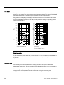
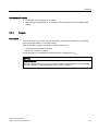
Figure 1-2
Example: M200D AS-i
The AS-Interface has the following advantages:
● Flexibility
● Cost effectiveness
● Simple and rapid installation with a minimum of errors
● A common line for transferring data and power
M200D AS-Interface Basic
Manual, 03/2009, A5E01668085-01
11
Introduction / product description
1.2 Fieldbus interfaces
Further information
● Catalogs, customer magazines, and brochures are available on the Internet
(http://www.automation.siemens.com/net/html_00/support/presales.htm)
● Brochure "Industrial communication for automation"
(http://www.automation.siemens.com/download/internet/cache/3/1462730/pub/en/bs_kschrift_en_0408.pdf)
(Introductory information about industrial communication):
● Catalog IK PI 2009 "Industrial Communication for Automation and Drives"
(http://www.automation.siemens.com/net/html_76/support/printkatalog.htm)
(Device overview and ordering data for industrial communication)
● "AS-Interface - The Solution for Automation" (http://www.asinterface.net/EN/System/Publications?)
(Compendium of technology, function and applications):
● AS-Interface homepage (http://www.as-interface.net/EN/Homepage?)
12
M200D AS-Interface Basic
Manual, 03/2009, A5E01668085-01
Product family
2.1
2
Motor starter M200D AS-Interface
The following motor starters with AS-Interface (AS-i) are available:
● M200D AS-i Basic
motor starter with thermistor motor protection + electronic motor model:
– Direct starter (electromechanical) (DSte) up to 5.5 kW,
Current ranges: 0.15 – 2 A and 1.5 – 12 A
– Reversing starter (electromechanical) (RSte) up to 5.5 kW,
Current ranges: 0.15 – 2 A and 1.5 – 12 A
– Direct starter (electronic) (sDSte) up to 4 kW,
Current ranges: 0.15 – 2 A and 1.5 – 9 A
– Reversing starter (electronic) (sRSte) up to 4 kW,
Current ranges: 0.15 – 2 A and 1.5 – 9 A
Order variants:
● Brake output for:
– 400/230 V AC
– 180 V DC
● Integrated manual operation (key-operated switch and keypad)
Accessories:
● Connection components (e.g. cables, connectors, etc.)
● Hand-held device
● Protection guard for the plug connections
M200D AS-Interface Basic
Manual, 03/2009, A5E01668085-01
13
Product family
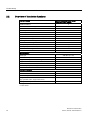
2.2 Overview of the device functions
2.2
Overview of the device functions
Device functions
Electromechanical (DSte, RSte)/
electronic (sDSte, sRSte)
Fieldbus interface
●
Control function: reversing starter
○
Control function: soft starter
—
Brake output 400 V / 230 V AC
○
Brake output 180 V DC
○
Thermal motor model
●
Temperature sensor (thermistor motor protection)
●
Asymmetry monitoring
●
Blocking current monitoring
●
Zero-current monitoring
●
M12 inputs (routed via AS-i)
4 (2)
M12 outputs (routed via AS-i)
1 (0)
Connector monitoring
●
Short-circuit protection
●
Communication
Slave type
Communication profile
Diagnostics via parameter channel (parameter echo)
A/B slave (4I / 3O)
7.A.E
●
Support for AS-i S1 status bit
●
Transfer of data sets via AS-i
—
Extended cyclic process image
—
Access via "Motor Starter ES"
—
Additional functions
Self-test
●
Local device interface
●
Disconnecting means
●
Integrated manual local control
(key-operated switch, keypad with LEDs)
○
Setting elements parameterized on device
●
● Integrated
○ Order variant
14
M200D AS-Interface Basic
Manual, 03/2009, A5E01668085-01
Product family
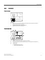
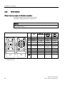
2.3 Design concept
2.3
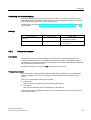
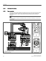
Design concept
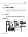
Connections and controls on the motor starter
$6L
$8;
6) '(9 )$8/7 67$7 3:5 3:5
0,4
0,6
0,8
1
1,2
0,3
0,2
le0,15
CLASS
OFF
2A
1,5
1,8
;
RQ
RII
RQ
7&
37& RII
;
RII
RQ
287
,1
;
,1
,1
,1
;
①
Disconnecting means (circuit breaker), can be locked
②
Optical device interface
③
M12 AS-i connection
④
Diagnostic LEDs
⑤
Cover (setting elements)
⑥
M12 output
⑦
M12 inputs
⑧
Protection guard for cables and connections (accessories)
⑨
Fixing holes for installation
⑩
400 V infeed
⑪
Motor connection
⑫
Key-operated switch (order variant)
⑬
Keypad for manual operation (order variant)
M200D AS-Interface Basic
Manual, 03/2009, A5E01668085-01
15
Product family
2.3 Design concept
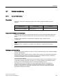
2.3.1
Operator controls
The motor starter is equipped with the following operator controls:
①
Key-operated switch (order variant)
②
Keypad (order variant)
③
Disconnecting means (circuit breaker)
④
Cover for parameter setting elements
Integrated manual local control (key-operated switch ① and keypad ②; order variant)
A key-operated switch and keypad are used for local operation.
The key can be inserted/removed in three positions.
Disconnecting means ③ (circuit breaker)
The disconnecting means is designed for the following individual functions:
● Disconnecting the series-connected consumers from the supply voltage
● Short-circuit protection of the series-connected consumer
● Switching on inhibited via padlock (max. three padlocks possible)
Parameter settings ④
The following setting elements can be found under the cover of the M200D AS-i Basic:
● Rotary coding switch for:
– Setting the rated operating current
– Deactivating the thermal motor model (class OFF)
● DIP switch for:
– Autoreset (ON / OFF)
– Connector monitoring (ON / OFF)
– Temperature sensor (ON / OFF)
– Temperature sensor (PTC / TC)
16
M200D AS-Interface Basic
Manual, 03/2009, A5E01668085-01
Product family
2.3 Design concept
2.3.2
Connections
Power terminals
①
Infeed for the three phases as well as the PE and N conductor via power connectors
(HAN Q4/2 with ISO23570 assignment)
②
Connection of the motor via power connectors
(HAN Q8/0 with ISO23570 assignment)
Control circuit / bus
①
AS-i bus connection with auxiliary voltage, M12 connector
②
Optical device interface (under the labeling strip) for connecting the hand-held device
③
1 x M12 output
④
4 x M12 inputs
• 2 inputs can be read via AS-i
• 2 inputs with fixed input function
M200D AS-Interface Basic
Manual, 03/2009, A5E01668085-01
17
Product family
2.3 Design concept
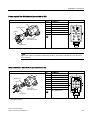
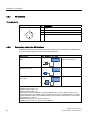
2.3.3
Status indicators
The following LEDs on the front of the starter indicate the device status:
①
Indicators for the device status and communication
②
Indicator for output OUT1
③
Indicators for inputs IN1 ... IN4
For a detailed description of the indicators, see "Diagnostics (Page 80)".
18
M200D AS-Interface Basic
Manual, 03/2009, A5E01668085-01
3
Functions
3.1
Overview of the device functions
Device functions
Electromechanical (DSte,
RSte)/
electronic (sDSte, sRSte)
Fieldbus interface (Page 22)
●
Control function: reversing starter (Page 23)
○
Brake output 400 V / 230 V AC (Page 23)
○
Brake output 180 V DC (Page 23)
○
Thermal motor model (Page 25)
●
Temperature sensor (thermistor motor protection) (Page 27)
●
Blocking protection (Page 29)
●
Zero-current monitoring (Page 29)
●
Asymmetry monitoring (Page 31)
●
M12 inputs (routed via AS-i) (Page 32)
4 (2)
M12 outputs (routed via AS-i) (Page 35)
1 (0)
Connector monitoring (Page 36)
●
Short-circuit protection (Page 38)
●
Communication
Slave type
Communication profile (Page 68)
A/B slave (4I / 3O)
7.A.E
Diagnostics via parameter channel (parameter echo) (Page 84)
●
Support for AS-i S1 status bit (Page 84)
●
Transfer of data sets via AS-i
—
Extended cyclic process image
—
Access via "Motor Starter ES"
—
Additional functions
Self-test (Page 41)
●
Local device interface (Page 43)
●
Disconnecting means (Page 38)
●
Integrated manual local control (Page 44)
(key-operated switch, keypad with LEDs)
○
Setting elements parameterized on device (Page 72)
●
● Integrated
○ Order variant
See also
Communication (Page 38)
M200D AS-Interface Basic
Manual, 03/2009, A5E01668085-01
19
Functions
3.2 Introduction
3.2
Introduction
Device functions
This section describes the device functions. All the device functions are assigned inputs (e.g.
device parameters) and outputs (e.g. messages).
The following schematic diagram illustrates the functional principle of the device:
,QSXWV
2XWSXWV
'HYLFHSDUDPHWHUV
&RPPDQGV
0HDVXUHGYDOXHV
'HYLFHIXQFWLRQ
3URWHFWLRQ
Figure 3-1
$ODUPV
$FWLRQV
Functional principle of the device
Self-protection
The motor protects itself against fatal damage by means of the thermal motor model and
temperature measurements for electronic switching elements.
Currents
Note
All current values (e.g. blocking current, current limits) are percentages of the rated
operating current set on the device (e.g. Ie = 2 A = 100 %).
20
M200D AS-Interface Basic
Manual, 03/2009, A5E01668085-01
Functions
3.3 Basic functions / parameters
3.3
Basic functions / parameters
Definition
Basic parameters are "central" parameters required by a range of device functions.
3.3.1
Rated operating current
Here, you can enter the rated operating current that the branch (switchgear and motor) can
carry without interruption. This is usually the rated motor current. The setting range depends
on the output class of the M200D motor starter (0.15 ... 2 A or 1.5 ... 12 A).
NOTICE
The rated operating current is one of the key parameters.
The rated operating current must always be set if motor protection is to be ensured via the
electronic overload relay.
The overload relay can be deactivated.
In this case, motor protection must be ensured by means of a thermistor in the motor.
Notes
● On the motor starter, the default rated operating current is set to the minimum value.
● The rated operating current for the M200D AS-i Basic motor starter is set by means of the
rotary coding switch. For more information, see Parameterization via local setting
(Page 72).
3.3.2
Protection against voltage failure
If the supply voltage fails, the last overload message "Overload" is retained.
M200D AS-Interface Basic
Manual, 03/2009, A5E01668085-01
21
Functions
3.4 Fieldbus interface
3.4
Fieldbus interface
Response to CPU / master STOP
If the fieldbus interface is interrupted, all control signals are set to 0.
Note
This is only relevant in "automatic" mode.
Group diagnosis
The controller is informed of whether or not a group fault message is present in the device
when "I/O fault bits" on the SAP status tab (S1 = 1) is set. The AS-i master enters the S1
value in the list of I/O faults (LPF) that have been signaled. The controller can read this list
via the "GET_LPF" command and then query a specific diagnostic value from the slave (see
also Diagnostics via parameter channel (parameter echo) (Page 84)).
The motor starter issues a fault message if a fault is present. In this case, the SF LED lights
up red.
Reference
For more information, refer to the documentation for your AS-i master.
22
M200D AS-Interface Basic
Manual, 03/2009, A5E01668085-01
Functions
3.5 Motor control
3.5
Motor control
3.5.1
Control function: reversing starter
Description
This control function allows the motor starter to control the direction in which motors rotate.
An internal logic prevents both directions of rotation from being activated simultaneously.
The delayed switchover from one direction of rotation to another is implemented by means of
the lock-out time, which is permanently set to 150 ms.
This function only applies to reversing starters.
3.5.2
Brake output
Description
A motor-mounted mechanical disk or spring-loaded brake is used to brake the motor. The
brake is controlled via the brake output.
Circuit diagram: example
The following circuit diagram illustrates the mechanical braking procedure with a 180 V DC
brake output:
Circuit diagram
Motor connector
/ / / 1
; 3(
3(
Name
1
Phase L1
2
—
3
Phase L3
4
Brake L1 (switched)
5
Thermistor
6
Brake L3 (direct)
7
Phase L2
,!! ,!! ,!!
Pin
8
Thermistor
PE (yellow/green)
; 3(
3(
;
0
M200D AS-Interface Basic
Manual, 03/2009, A5E01668085-01
23
Functions
3.5 Motor control
Brake output
Externally-supplied motor brakes are usually powered via a jumper on the motor terminal
board.
Since switching the motor and brake simultaneously can increase wear and tear to the
brake, all M200D motor starters can be fitted with an optional electronic brake controller.
Depending on the order variant, the following externally-supplied brake coils can be
controlled:
● 400 V AC / 230 V
(The brake rectifier must be installed in the motor. The rectifier input is controlled via the
motor starter).
● 180 V DC
(A rectifier is not required for the brake in the motor because the motor starter provides
the 180 V DC. In this way, brake coils for 180 V DC can be switched directly).
The brake voltage is fed to the motor together with the motor infeed via a joint cable (e.g.
6 x 1.5 mm2). For more information about connecting the brake output, see section Brake
output (Page 60).
Brake release delay at startup
A fixed ON-delay time of 40 ms is set for the M200D AS-i Basic motor starter to prevent wear
and tear to the brake (e.g. the motor output is activated 40 ms after the brake output).
In reversing mode, the release delay does not begin until the lock-out time has expired.
24
M200D AS-Interface Basic
Manual, 03/2009, A5E01668085-01
Functions
3.6 Motor protection
3.6
Motor protection
3.6.1
Thermal motor model
Description
The approximate temperature of the motor is calculated using the measured motor currents
and device parameters "Rated operating current" and "Tripping class". This indicates
whether the motor is overloaded or functioning in the normal operating range.
Motor protection shutdown response
You use this device parameter to specify how the motor starter is to respond in an overload
situation:
● Shutdown without restart (AUTO RESET = off)
Following an overload situation, the shutdown command cannot be reset until the motor
model has fallen below the reset threshold and after a reset command has been issued
(trip reset).
● Shutdown with restart (AUTO RESET = on)
WARNING
Motor restarts automatically if AUTO RESET is on.
Can Cause Death, Serious Injury, or Property Damage
The motor starter restarts automatically after the recovery time if a start command is
present (autoreset). (autoreset).
Make sure that you take appropriate measures to exclude the risk of hazardous conditions.
M200D AS-Interface Basic
Manual, 03/2009, A5E01668085-01
25
Functions
3.6 Motor protection
Trip class
The trip class (CLASS) specifies the maximum time within which a protective device must
trip from a cold state at 7.2 x the setting current (motor protection to IEC 60947). The M200D
AS-i Basic trip class is set permanently to CLASS 10 and can be deactivated.
0LQ
&/$66
&/$66
[Ie
SROHV\PPHWULFDOORDG
&/$66
tA
V
V
&/$66
tA
0LQ
If the setting is changed to CLASS OFF, the "thermal motor model" function is deactivated
along with the accompanying messages. With the M200D AS-i Basic, the thermal motor
model is deactivated by means of the rotary coding switch for setting the operating current
(CLASS OFF position).
[Ie
SLQORDG
IDLOXUHRISKDVHRU
FXUUHQWLPEDODQFH!
Note
Deactivation rule
To ensure motor protection, the motor cannot be switched on when the temperature sensor
is deactivated and, at the same time, CLASS OFF is set. This is indicated on the M200D ASi Basic with either an alarm (if an ON command is not present) or a fault (if an ON command
is present).
Recovery time
The recovery time is the time defined for cooling after which the system can be reset
following an overload trip. The recovery time for the M200D AS-i Basic is set permanently to
90 s.
Trip reset signals present during the recovery time have no effect.
Voltage losses occurring before this time expires can prolong the recovery time.
26
M200D AS-Interface Basic
Manual, 03/2009, A5E01668085-01
Functions
3.6 Motor protection
Prewarning limit for motor heating
The motor starter also assumes a prewarning role, that is, it issues a warning if the motor
temperature limit is exceeded. The prewarning limit for the M200D AS-i Basic is 90 % of the
motor heating value. The motor is shut down at 100 %.
The alarm can be read via Diagnostics via parameter channel (parameter echo) (Page 84)
for the starter.
Settings
Device parameter
3.6.2
Default setting
Setting range
Motor protection shutdown
response
Shutdown without restart
•
•
Shutdown without restart
Shutdown with restart
Trip class
CLASS 10
•
•
CLASS 10
CLASS OFF
Temperature sensor
Description
Temperature sensors are used to directly monitor the motor winding temperature. This
indicates whether the motor is overloaded or functioning normally. If temperature sensors
are installed in the motor stator winding (order option for the motor), the M200D motor starter
can use these to monitor the motor.
M200D motor starters can evaluate one temperature sensor circuit.
Temperature sensor
You can activate or deactivate this parameter depending on whether or not a temperature
sensor is installed in the motor. The setting is made by means of the DIP switch on the
device.
Two types of temperature sensor are supported:
● Thermoclick.
This is a switch that opens at a certain winding temperature.
● PTC type A.
This is a PTC thermistor with a characteristic to IEC 60947-8.
When the PTC type A temperature sensor is active, temperature sensor monitoring is also
activated (see below).
M200D AS-Interface Basic
Manual, 03/2009, A5E01668085-01
27
Functions
3.6 Motor protection
Motor protection shutdown response
You can use this parameter to determine how the motor starter is to respond to a
temperature sensor or thermal motor model overload:
● Shutdown without restart (AUTO RESET = off)
● Shutdown with restart (AUTO RESET = on)
WARNING
Motor restarts automatically if AUTO RESET is on.
Can Cause Death, Serious Injury, or Property Damage
The motor starter restarts automatically after the recovery time if a start command is
present (autoreset). (autoreset).
Make sure that you take appropriate measures to exclude the risk of hazardous conditions.
Temperature sensor monitoring
Temperature sensor monitoring is activated when a PTC type A temperature sensor is
parameterized.
This device parameter monitors the temperature sensor cable for interruptions (wire
breakage) and short-circuits. The motor is shut down if either of these scenarios occurs.
Settings
The possible settings for the M200D AS-i Basic motor starter can be found in section
Parameterization via local setting (Page 72).
28
M200D AS-Interface Basic
Manual, 03/2009, A5E01668085-01
Functions
3.7 System monitoring
3.7
System monitoring
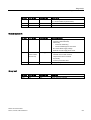
3.7.1
Current limit values
Description
The motor current and current limit values can be used to determine different system
statuses:
System status
Current value
Protection by
Motor blocked
Very high current flowing
Blocking protection
Motor runs at no load (e.g.
because system is damaged)
Very low current flowing
(< 18.75 % of Ie)
Residual current detection
Response to residual current detection
Residual current detection responds when the motor current in all three phases falls below
18.75 % of the set rated operating current. In this case, the motor starter shuts down the
motor.
Residual current detection is deactivated by setting the rotary coding switch to
"CLASS OFF".
Note
When the motor is switched on, residual current detection is suppressed for around 1
second.
Blocking current monitoring
The blocking current specifies how much current is consumed by the motor (at rated voltage)
when the axis blocked.
The blocking current monitoring function detects when a motor axis is blocked mechanically.
The block causes the motor to consume more power. The "blocking current" is a defined
monitoring threshold for the motor current consumption.
It is monitored as follows:
When the motor starts, the tripping limit for the blocking current is set permanently to 800 %
of the rated operating current for a period of 10 s. During operation, the "blocking current"
tripping limit is set permanently to 400 % of the rated operating current.
If the blocking current is exceeded, the motor starter detects blocking. Blocking time
monitoring is activated as of the point at which the blocking current is exceeded. If the
blocking current flows for longer than the blocking time, the motor starter automatically
generates a shutdown command.
M200D AS-Interface Basic
Manual, 03/2009, A5E01668085-01
29
Functions
3.7 System monitoring
The blocking current monitoring function is deactivated by setting the rotary coding switch to
"CLASS OFF".
Note
If the blocking time expires and the system is still blocked, the motor starter is shut down.
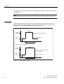
Blocking time
The blocking time is the time a block can be present before the motor shuts down. If the
blocking time expires and the system is still blocked, the motor starter is shut down. The
blocking time in the M200D AS-i Basic is set permanently to 1 s.
6FHQDULR0RWRUFRQWLQXHVWRUXQ
6WDOOHGURWRU
%ORFNLQJ
FXUUHQW
%ORFNFDQFHOHGZLWKLQEORFNLQJ
WLPH
0RWRUFRQWLQXHVWRUXQ
0RWRU
FXUUHQW
%ORFNLQJWLPH
W
6FHQDULR0RWRULVVKXWGRZQ
6WDOOHGURWRU
%ORFNLQJ
FXUUHQW
%ORFNVWLOOSUHVHQWDIWHUEORFNLQJ
WLPHKDVHODSVHG
0RWRU
FXUUHQW
0RWRULVVKXWGRZQ
%ORFNLQJWLPH
Figure 3-2
30
W
Block protection principle
M200D AS-Interface Basic
Manual, 03/2009, A5E01668085-01
Functions
3.7 System monitoring
3.7.2
Asymmetry monitoring
Description
Three-phase induction motors respond to slight asymmetries in the supply voltage with a
higher asymmetric current consumption, which causes the temperature in the stator and
rotor windings to increase. In this case, the M200D motor starter protects the motor against
overload by shutting it down.
Note
When the motor is switched on, asymmetry evaluation is suppressed for approx. 0.5 s.
Asymmetry limit value
The asymmetry limit is a percentage value by which the motor current is allowed to deviate
in each phase.
Asymmetry occurs when the difference between the lowest and highest phase current is
greater than the asymmetry limit value. The asymmetry limit for the M200D AS-i Basic is set
permanently to 30 %.
The reference value for the evaluation is the maximum phase current in one of the 3 phases.
Response to asymmetry
If the asymmetry limit value is exceeded, the motor starter is shut down.
M200D AS-Interface Basic
Manual, 03/2009, A5E01668085-01
31
Functions
3.7 System monitoring
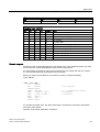
3.7.3
Inputs
Description
The motor starter can use the "inputs" function to execute various actions, whereby the
signals at the digital inputs are evaluated. You can connect the inputs directly to sensors
(PNP) (2 and 3-wire system).
The input actions of the individual digital inputs affect the motor starter functions (=OR
operation) independently of one another.
The signals of inputs IN1 and IN2 are transferred cyclically via the process image.
NOTICE
Potential transfer
With AS-i, digital inputs must not be connected to digital outputs because this can establish
an impermissible connection between the UAS-i and UAUX voltages.
Input function
,1[
W
PVIL[HG
6
4
1RWUHWHQWLYH
,QSXWVLJQDOGHOD\
DIIHFWVDOOLQSXWV
5
UHWHQWLYH
IRUTXLFNVWRSRQO\
5HVHWVLJQDO
0RWRU2))
4XLFNbVWRSGLVDEOH
,QSXW
QVLJQDO
3URFHVVLPDJH
$FWLRQ
,QSXWQDFWLRQ
4XLFNVWRS
(PHUJHQF\VWDUW
7ULSSLQJOLPLWSRVLWLRQ&:
7ULSSLQJOLPLWSRVLWLRQ&&:
6KXWGRZQZLWKUHVWDUW
Figure 3-3
32
Overview of input parameters
M200D AS-Interface Basic
Manual, 03/2009, A5E01668085-01
Functions
3.7 System monitoring
Input n signal
The input level of the digital inputs is stored for inputs IN1 and IN2, that is, the active edge
executes the input action assigned to the corresponding input. Regardless of the input signal
present, the action can only be deactivated again by a further event.
The input level is not stored for inputs IN3 and IN4. This input action is active as long as the
input is active.
Input n level
The input logic for the M200D AS-i Basic is set to "NO contact".
Setting
Device parameter
.DS...
.RS...
Input signal delay
10 ms
10 ms
Input 1 level
NO contact
NO contact
Input 1 action
Quick stop
Quick stop
Input 2 action
No action
No action
Input 3 action
Emergency start
Tripping limit position CW
Input 4 action
Shutdown with restart
Tripping limit position CCW
Input 1 signal
Latching (edge evaluation)
Latching (edge evaluation)
Input 2 signal
Unlatching (level evaluation)
Unlatching (level evaluation)
Input 2 level
Input 3 level
Input 4 level
Input 3 signal
Input 4 signal
M200D AS-Interface Basic
Manual, 03/2009, A5E01668085-01
33
Functions
3.7 System monitoring
Description of the actions
Quick stop
● The motor and brake output are shut down without a group fault.
● "Quick stop" has priority over "Motor CW" and "Motor CCW".
● The input action responds to the active edge of the input signal, which means that
deactivation is possible when the static input signal "Quick stop" is present.
● The input trigger is reset when the "Motor CW"/"Motor CCW" control commands are
canceled or by means of "Disable quick stop" (in the process image).
Note
When bit DO2 (PIO) (Disable quick stop) is set, input 1 in the PII can be used as a free
input because the input function "Quick stop" is deactivated.
Example:
'2PRWRUULJKW
',LQSXW
4XLFNVWRSIXQFWLRQ
'2'LVDEOHTXLFNVWRS
0RWRU
Figure 3-4
Example: quick stop
Emergency start
● Starts the motor when an ON command is issued despite the fact that an internal
shutdown command is present.
● Switches on the brake output too if an ON command is present for this.
● The self-protection function of the motor starter remains active and prevents the device
from being destroyed.
Tripping limit position CW/CCW
● The motor and the brake output are tripped regardless of the direction of rotation.
● The brake output can be switched on again once the "Brake" and "Motor CW / CCW"
control commands have been canceled.
● Tripping limit position CW: The motor can only be switched on again with the opposite
command ("Motor CCW").
● Tripping limit position CCW: The motor can only be switched on again with the opposite
command ("Motor CW").
34
M200D AS-Interface Basic
Manual, 03/2009, A5E01668085-01
Functions
3.7 System monitoring
Shutdown with restart
● Causes the motor and brake to shut down.
● Acknowledged automatically once the cause of the shutdown has been rectified (initial
status).
3.7.4
Outputs
Description
The motor starter can use the "outputs" function to control various actuators (e.g. indicator
lights, signal transmitters, or contactor relays).
With the M200D AS-i Basic, the output is active in the event of...
● Group faults (permanently assigned)
...and outputs a continuous signal.
The digital output is overload/short-circuit proof and is supplied from UAUX.
NOTICE
Potential transfer
With AS-i, digital inputs must not be connected to digital outputs because this can establish
an impermissible connection between the UAS-i and UAUX voltages.
M200D AS-Interface Basic
Manual, 03/2009, A5E01668085-01
35
Functions
3.7 System monitoring
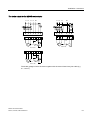
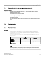
3.7.5
Connector monitoring
3.7.5.1
Power connector
The motor starter monitors whether the infeed connector on the line side of the motor starter
is plugged in. Connector monitoring is implemented by means of an input activated via a
jumper between pins 11 and 12, which informs the motor starter that the connector is
plugged in.
Note
When you use the "connector monitoring" function, you have to connect pin 11 to pin 12 in
the connector.
_!_!_!
;
/ / / 1 3(
3(
;
;
7 7 / / / 3( %2 %2 1
7 7 / / / 3( %2 %2 1
/ / / 1 3(
0
/
/
/
1
3(
3(
37&RU
WKHUPRFOLFN
6XSSO\IRUPDLQSRZHU
① Temperature sensor monitoring
② Connector monitoring
36
;
M200D AS-Interface Basic
Manual, 03/2009, A5E01668085-01
Functions
3.7 System monitoring
Connector monitoring
Line-side connector monitoring can be deactivated via the DIP switch.
For more information, see Parameterization via local setting (Page 72).
Response when connector is unplugged
When the connector is unplugged, the motor starter outputs a group fault.
Settings
Device parameter
Connector monitoring
3.7.5.2
Default setting
Line side
Setting range
•
•
Deactivated
Line side
Motor connector
The "connector monitoring" function is only valid for the infeed connector.
A connector monitoring function for the motor connector can be logically combined with the
thermistor cable and/or thermistor evaluation function.
If a motor is operated without a thermistor, you can activate thermistor monitoring
(thermoclick) and use it to monitor the connector by means of a wire jumper on the motor
terminal board or in the motor connector.
Note
The "overload" message must be interpreted to mean that the motor connector has been
unplugged.
M200D AS-Interface Basic
Manual, 03/2009, A5E01668085-01
37
Functions
3.8 Short-circuit protection (circuit breaker / disconnecting means)
3.8
Short-circuit protection (circuit breaker / disconnecting means)
Description
The motor starter is equipped with an integrated circuit breaker for short-circuit protection to
ensure that the system is safe and to protect personnel. Short-circuits between one phase
and ground (= ground fault) as well as between two phases are monitored.
Properties of the circuit breaker
The circuit breaker / disconnecting means is designed for the following functions:
● Disconnecting the series-connected starter and consumer from the supply voltage
● Closing lockout by means of a padlock on the rotating element
● Short-circuit protection for the series-connected consumer with circuit breaker
Response when circuit breaker is OFF:
If a short circuit occurs or the circuit breaker is tripped manually, the motor starter responds
with a group fault.
3.9
Communication
Description
Communication is a higher-level device function comprising a number of sub-functions:
● Mode monitoring
● Fieldbus interface
● Data plausibility check
● Message output
38
M200D AS-Interface Basic
Manual, 03/2009, A5E01668085-01
Functions
3.9 Communication
3.9.1
Mode monitoring
Data channels
The M200D AS-i Basic motor starter has three different data channels:
● Local optical device interface (for hand-held device)
● Control with integrated manual local control in "Manual operation local" mode
(key-operated switch + keypad; order variant)
● Via the fieldbus interface AS-Interface:
– Cyclic data via AS-i
The data channel used for control purposes depends on the operating mode.
Operating modes
The following operating modes are available (in ascending order of priority):
● Automatic (lowest priority)
The motor starter can only be controlled with the PLC via the fieldbus.
● Manual operation local
The motor starter can be controlled with:
– Integrated manual local control (key-operated switch + keypad; order variant)
– Local device interface (e.g. hand-held device) (highest priority)
In this operating mode, the message "Manual local operation" is output when diagnosis is
performed via the parameter channel.
3.9.2
Plausibility check for settings
Description
The motor starter checks all the parameters that have been set to ensure that they are valid
and plausible.
Motor protection deactivation rule
At least one of the motor protection functions supported by the motor starter (thermal motor
model, temperature sensor) must always be active at any one time, that is, you are not
permitted to deactivate all the motor protection functions by means of parameterization.
If the temperature sensor is deactivated via the DIP switch and, at the same time, the rotary
coding switch is set to "Class OFF", the following applies:
M200D AS-Interface Basic
Manual, 03/2009, A5E01668085-01
39
Functions
3.9 Communication
● If no motor ON command is present, a group alarm is output.
The alarm is canceled when motor protection is reactivated.
● If a motor ON command is present, a group fault is output immediately and a
corresponding internal shutdown command generated, which must be acknowledged with
"trip reset".
– If the motor ON command remains, the fault can only be acknowledged with "trip
reset" once the fault has been rectified (activate at least one motor protection
function).
– If the motor ON command is reset, the group fault can be "downgraded" to a group
alarm even if a setting is incorrect.
3.9.3
Message output
Message
Meaning
Output via
General messages
Device can be controlled via BUS
Automatic mode
No fault
Ready (automatic)
•
•
•
Group fault
At least one fault is set.
•
•
LED
Diagnostics via parameter
channel
Group alarm
At least one alarm is present.
•
•
LED
Diagnostics via parameter
channel
Manual operation via integrated
manual local control or via the local
device interface (hand-held device)
Diagnostics via parameter channel
Process image of inputs
Mode monitoring
Manual operation
local mode
40
M200D AS-Interface Basic
Manual, 03/2009, A5E01668085-01
Functions
3.10 Trip reset
3.10
Trip reset
Trip reset acknowledges all the faults that are currently present in the starter and that can be
acknowledged. A fault can be acknowledged if its cause has been rectified or if it is no longer
present.
The trip reset can be triggered by:
● Remote reset via the bus interface (DO 0 CW ON and DO 1 CCW ON simultaneously)
● Local reset via the key-operated switch (0 position; order option)
● Local reset via the device interface (hand-held device)
3.11
Self-test
Description
Two types of self-test can be carried out:
● Self-test at startup
This is automatically selected when the device is switched on or initialized.
● Self-test during operation:
The motor starter monitors (cyclically) specific device components and signals any faults
(device faults).
Self-test fault
If a fault occurs, the "DEVICE" LED lights up red. The fault can only be acknowledged by
switching the device off and then on again. If the fault is still present, the self-test will return a
fault again when the device is switched on. In this case, the motor starter must be replaced.
Note
Specific device components are monitored continuously (internally) by the motor starter and
the results signaled with the message "Device fault".
M200D AS-Interface Basic
Manual, 03/2009, A5E01668085-01
41
Functions
3.12 Solid-state/mechanical switching technology
3.12
Solid-state/mechanical switching technology
Solid-state switching
The motor starter controls the motor (two phases) with thyristors. Phase L1 is not switched
but is instead looped through from the 400 V power connection to the motor connection via
the integrated disconnecting means.
DANGER
Hazardous voltage
Can cause death or serious injury.
If the line voltage is present at the 400 V power connection of the motor starter, hazardous
voltage may still be present at the motor starter output even if a start command has not
been issued.
When carrying out any work on the branch, make sure that you disconnect it via the
disconnecting means.
Mechanical switching
The motor starter controls the motor (three phases) with contactors.
On device versions with a rated operating current of 0.15 - 2A (3RK13..-6KS41) RC
elements are integrated on the motor output side to dampen interference pulses.
Contact block defective
If a contact block is defective (contactor welded / thyristor failure), the motor starter cannot
shut down the motor.
If necessary, evaluate the message "Device fault" and shut down the branch on the basis of
this by means of an upstream contact block.
42
M200D AS-Interface Basic
Manual, 03/2009, A5E01668085-01
Functions
3.13 Local device interface
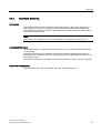
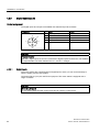
3.13
Local device interface
Description
The local optical device interface can be used to connect the motor starter to a hand-held
device (order no.: 3RK1922-3BA00; RS232 interface cable: 3RK1922-2BP00). This control
source has the highest priority.
To stop the fiber-optic cable for the device interface from getting dirty, it is located under the
removable unit labeling plate.
Figure 3-5
Optical device interface
NOTICE
To ensure that data can be transferred without any problems, make sure that the device
interface is clean at all times.
M200D AS-Interface Basic
Manual, 03/2009, A5E01668085-01
43
Functions
3.14 Integrated manual local control
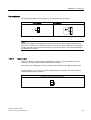
3.14
Integrated manual local control
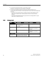
Integrated manual local control (order variant) for the M200D motor starter involves a keyoperated switch and a keypad with four pushbuttons.
Key-operated switch
2
Figure 3-6
Key-operated switch
The key-operated switch can be set to three different positions.
Position
2
Meaning
Function
Automatic mode
The keys on the keypad have no function. The LEDs on
the "QUICK STOP DISABLE", "RIGHT", and "LEFT" keys,
however, are active. They are used for indicating the status
(= status of control via the PIO).
Manual mode
Control priority is assumed by a lower-priority control
source (automatic mode) and transferred to the keypad.
When you switch back to "REMOTE", control priority is
always initially passed to the CPU/master.
OFF / Reset
When you switch to this position, a fault that is present can
be acknowledged with trip reset (provided that it can be
reset). If the key-operated switch remains in this position,
the motor starter is in the "O" position once the "Reset"
command has been issued. The motor starter does not
execute any control commands in this position (regardless
of the control source).
Note
The key can be inserted/removed in any position.
44
M200D AS-Interface Basic
Manual, 03/2009, A5E01668085-01
Functions
3.14 Integrated manual local control
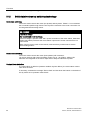
Keypad
The keypad has four pushbuttons arranged in a square.
Note
They are only active when the key-operated switch is set to manual mode.
Figure 3-7
Pushbutton
Keypad
Meaning
Function
Continuous
operation / jog
mode
The mode switches every time you press this pushbutton (continuous / jog).
"Continuous" mode is indicated via the corresponding LED (yellow, lit up) (in
manual mode only).
When manual mode is deactivated, jog mode is reset.
Quick stop
DISABLE
The "QUICK STOP" input actions are deactivated for all inputs.
This pushbutton is active in jog mode and continuous operation. In continuous
operation, the "QUICK STOP DISABLE" function can be activated by pressing the
pushbutton once and deactivated by pressing it again.
The yellow LED lights up regardless of the operating mode (as long as the function
is active).
Clockwise
rotation
The main circuit for CW operation is activated.
In continuous operation, the main circuit can be activated by pressing the
pushbutton once and deactivated by pressing it again.
With reversing starters, an ongoing action can also be interrupted in continuous
operation by pressing the "CCW rotation" pushbutton.
The green LED lights up regardless of the operating mode (as long as the selected
function is active).
CCW rotation
This pushbutton is only enabled for reversing starters.
The main circuit for CCW operation is activated.
In continuous operation, the main circuit can be activated by pressing the
pushbutton once and deactivated by pressing it again.
In continuous operation, an ongoing action can also be interrupted by pressing the
"CCW rotation" pushbutton.
The green LED lights up regardless of the operating mode (as long as the selected
function is active).
M200D AS-Interface Basic
Manual, 03/2009, A5E01668085-01
45
Functions
3.14 Integrated manual local control
Note
If the "CW rotation" and "CCW rotation" pushbuttons are pressed simultaneously, this is
classed as an operation fault. A function cannot be restarted. A function that is being
executed is interrupted (the starter shuts down).
A function cannot be restarted until both pushbuttons have been released.
46
M200D AS-Interface Basic
Manual, 03/2009, A5E01668085-01
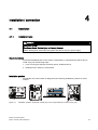
Installation / connection
4.1
Installation
4.1.1
Installation rules
4
DANGER
Hazardous voltage
Can Cause Death, Serious Injury, or Property Damage
Before starting work, disconnect the system and devices from the power supply.
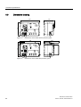
Simple installation
The distributed M200D AS-i motor starter is designed as a complete device that is easy to
install. Carry out the following steps:
1. If you are using the optional protection guards, install these first.
2. Install the motor starter on a flat surface.
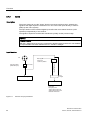
Installation position
The M200D AS-i motor starter is designed for the following installation positions on a flat
surface:
Figure 4-1
Installation positions: horizontal, vertical, flat; must not be positioned as shown on the right
M200D AS-Interface Basic
Manual, 03/2009, A5E01668085-01
47
Installation / connection
4.1 Installation
4.1.2
Derating
What is derating?
Derating allows devices to be used even in severe operating conditions by selectively
restricting the output capacity.
Derating factors
When M200D AS-i motor starters are operated under harsh conditions, the following factors
must be taken into account:
● Ambient temperature Tu:
– The ambient temperature Tu is the temperature of the air surrounding the motor starter
housing.
The lower the maximum ambient temperature Tu, the higher the current load on the
motor starter can be.
– The installation position affects how quickly the motor starter cools.
● Absolute current load:
– The lower the current flowing through the motor starter, the lower the power loss
(= heat) inside the device. If slight self-heating occurs, the ambient temperature Tu can
be higher.
– In the case of soft starters in which the soft start function has been deactivated, the
maximum permissible rated operating current Ie is restricted to 9 A (≡ electronic direct
starter; sDSte).
48
M200D AS-Interface Basic
Manual, 03/2009, A5E01668085-01
Installation / connection
4.1 Installation
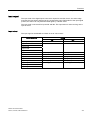
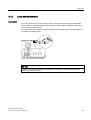
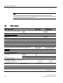
Derating diagrams
You can use the following diagrams to determine the derating factors for horizontal, vertical,
or flat installation.
, H >$ @
①
DSte, RSte
②
sDSte, sRSte
Figure 4-2
M200D AS-Interface Basic
Manual, 03/2009, A5E01668085-01
7 X >r& @
Derating for horizontal installation (Basic)
49
Installation / connection
4.1 Installation
, H >$ @
①
DSte, RSte
②
sDSte, sRSte
Figure 4-3
7 X >r& @
Derating for vertical installation
, H >$ @
①
DSte, RSte
②
sDSte, sRSte
Figure 4-4
50
7 X >r& @
Derating for flat installation
M200D AS-Interface Basic
Manual, 03/2009, A5E01668085-01
Installation / connection
4.1 Installation
4.1.3
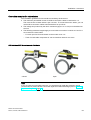
Installing the protection guards
Protection guard (accessory)
CAUTION
The protection guards are designed for a maximum load of 10 kg.
To prevent mechanical damage to the motor starter cables and connections, you can install
protection guards on the side and top (order no.: 3RK1911-3BA00).
To secure the protection guards, the angled ends can be used as clamping bolts, which are
secured in the device base by means of eccentric elements.
1.
Insert the eccentric elements in the locating holes on the bottom of the motor starter.
Make sure that the holes are aligned for the protection guards.
2.
Push the ends of the protection guards into the holder until they engage.
3.
Turn the eccentric elements clockwise until the protection guard is secure.
M200D AS-Interface Basic
Manual, 03/2009, A5E01668085-01
51
Installation / connection
4.1 Installation
4.1.4
Installing the motor starter
Carry out the following steps to install the motor starter:
Step
Description
1
Find a flat surface for mounting the device.
2
Drill four holes for the screws.
3
4.1.5
Secure the motor starter using four screws (M5). If necessary, use plain washers and
spring washers.
Functional ground
The motor starter must be connected to functional ground. The connection to functional
ground is required to discharge interference and ensure EMC resistance. Unlike the
protective conductor, functional ground does not offer protection against electric shock,
which is why it must be routed separately.
The contact plate at the fixing point on the bottom right is connected to functional ground
within the device. This connection must be connected to the ground potential with as little
resistance as possible.
Figure 4-5
Connection for functional ground
If you do not install the motor starter on a grounded, conductive base, you have to establish
a connection with the ground potential (grounding cable with cable lug, spring washer, and
plain washer).
52
M200D AS-Interface Basic
Manual, 03/2009, A5E01668085-01
Installation / connection
4.1 Installation
4.1.6
Setting the AS-i address
Unique addressing
In the factory setting, an I/O module (slave) has the address 0. It is detected by the master
as a new slave that has not yet been addressed and, in this condition, has not yet been
integrated in standard communication/data exchange.
To enable data to be exchanged between the master and slaves, you have to assign a
unique address for each slave (i.e. each slave address must be different) when
commissioning the AS-Interface network.
You can select any address in the address space from 1A to 31A and 1B to 31B.
Thus a maximum of 62 nodes are possible in one AS-Interface network.
Addressing the slaves
You can set the slave address in different ways:
● Offline with the addressing unit at the AS-i connection.
Recommended if you want to assign addresses for the entire system. The direct
connection between the slave (motor starter) and addressing unit ensures that the slaves
are not mixed up.
● Online by the AS-i master or in the PLC configuration software.
Recommended if you want to assign addresses to individual slaves if an addressing unit
is not available.
Before assigning addresses, you must ensure that each address exists only once in the
AS-i network, that is, several new, additional modules (with address 0 in as-delivered
condition) must not be connected to the AS-i cable.
CAUTION
As soon as you have assigned a valid address outputs can be set or inputs read that result
in follow-up switching operations. To prevent a hazardous condition switch off the voltage
UAUX.
M200D AS-Interface Basic
Manual, 03/2009, A5E01668085-01
53
Installation / connection
4.1 Installation
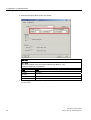
Offlline addressing with the addressing unit
The motor starter is addressed via the AS-i connection socket.
Note
When assigning the address via the addressing unit, unscrew the encoders (sensors) from
the digital inputs to prevent the addressing unit from being overloaded by their power
consumption.
If the older version of the addressing unit (3RK1904-2AB00) is used, a special addressing
cable (3RK1901-3RA00) is required to connect the module to the addressing unit.
ASI+
ASI3 2 4 1
1. Connect the motor starter to the addressing unit (3RK1904-2AB01) using a standard M12
connection cable (2 or 3 pin) (e.g. 3RX8000-0GF32-1AB5).
(4 or 5-pin connection cables must not be used for addressing purposes.)
2. Assign an address to the module.
• Set the selector switch to ADDR.
•
•
Press
. The address of the connected module is read and displayed.
.
Select the address by choosing
•
To transfer the address to the module, choose
.
3. Unplug the addressing cable and reconnect the motor starter using the AS-i cable.
Online addressing with the AS-i master and in the PLC configuration software
For instructions on how to address the motor starter using the AS-i master or in the
configuration software, refer to the manual for the AS-i master you are using.
54
M200D AS-Interface Basic
Manual, 03/2009, A5E01668085-01
Installation / connection
4.2 Connection
4.2
Connection
More connection technology products can be found in "Siemens Solution Partners"
(www.siemens.com/automation/partnerfinder) under "Distributed Field Installation System".
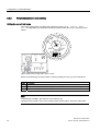
4.2.1
Required components/cables
Selecting the power cables
DANGER
Hazardous voltage
Can Cause Death, Serious Injury, or Property Damage
Before starting work, disconnect the system and devices from the power supply.
The cross-section of the power cables must be suitable for the prevailing ambient conditions.
The following factors determine the cross-section:
● The current set on the device
● The cable installation type
● The ambient temperature
● The type of material (PVC, rubber)
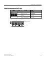
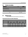
The following maximum current-carrying capacities apply for PVC power cables when
installed, for example, in the cable duct (depending on the ambient temperature):
Cross-section
TU = 30 °C
TU = 40 °C
TU = 45 °C
TU = 50 °C
TU = 55 °C
1.5 mm2
14 A
12.2 A
11.1 A
9.9 A
8.5 A
2.5
mm2
19 A
16.5 A
15.0 A
13.5 A
11.6 A
4.0
mm2
26 A
22.6 A
20.5 A
18.5 A
15.9 A
M200D AS-Interface Basic
Manual, 03/2009, A5E01668085-01
55
Installation / connection
4.2 Connection
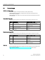
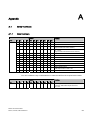
Note the following rules when carrying out wiring:
Rules for flexible cables
Data
Current-carrying capacity of the plug connection as a function of the
connectable core cross-sections and ambient temperature
TU =
55 °C
TU =
40 °C
1.5 mm2
12 A
15 A
2.5 mm2
20 A
25 A
mm2
30 A
35 A
4.0
Unused connections
Seal unused connections by means of the sealing caps enclosed since this is the only way to
ensure degree of protection IP65.
The sealing caps are also available as accessories:
4.2.2
Item
Quantity
Order no.
Sealing cap M12
10 pieces
3RX9802-0AA00
Prefabricating power cables
To prefabricate power cables, you require the following:
● A crimping tool for attaching the sockets and pins on the individual wires
● For infeed on motor starters
Assignment of X1: see section Power terminal (Page 58):
– A flexible Cu cable with 4 x 2.5 mm2 / 4 mm2 / 6 mm2 (3 wire + PE)
(for motor starters with 230 V AC brake output: 5-core cable; 3 wire + N + PE)
– Han Q4/2 socket power connector
Item
Quantit Order no.
y
Contact socket 2.5 mm2, for Han Q4/2 sockets
5
3RK1911-2BE50
for Han Q4/2 sockets
5
3RK1911-2BE10
Contact socket 6 mm2, for Han Q4/2 sockets
5
3RK1911-2BE30
Contact socket 4
56
mm2,
Crimping tool ≤ 4 mm²
1
3RK1902-0CT00
Crimping tool 4 / 6 mm²
1
3RK1902-0CW00
M200D AS-Interface Basic
Manual, 03/2009, A5E01668085-01
Installation / connection
4.2 Connection
Consumer connection on the motor starter
For the assignment of X2, see Power terminal (Page 58):
● A flexible Cu cable with 1.5 mm2 or 2.5 mm2
– Without brake control: 3 wire + PE
– With brake control: 5 wire + PE
– With temperature sensor: 2 additional wires
– Han Q8/0 pin power connector
Item
Order no.
Connector set, 8 X 1.5
4.2.3
mm2,
9 pin, complete with PG16 cable entry
3RK1902-0CE00
Connector set, 8 X 2.5 mm2, 9 pin, complete with PG16 cable entry
3RK1902-0CC00
Installing and wiring power connectors
DANGER
Hazardous voltage
Can Cause Death, Serious Injury, or Property Damage
Before starting work, disconnect the system and devices from the power supply.
Installa and wire the power connectors as follows:
Step
Procedure
1
Route the cable through the cable gland, sealing insert (enclosed), and the connector housing. The sealing
insert is available in the following gradings:
Permissible external diameter of the cable
Sealing insert
7.0 to 10.5 mm
9.0 to 13.0 mm
11.5 to 15.5 mm
Green
Red
White
2
Strip the cable over a length of 20 mm.
3
Strip the cores over a length of 8 mm.
4
Secure the contact sockets/pins on the cores by crimping or soldering them.
5
Sort the contact sockets/pins in the socket/pin insert in accordance with the assignments (see section Power
terminal (Page 58)). The contact sockets/pins should not engage yet. Make sure that they are correctly
assigned. Push the contact sockets/pins into the socket/pin insert until they engage. Use a suitable tool to
remove contact sockets/pins that have already been installed (Han Q4/2: 3RK1902-0AB00, Han Q8/0:
3RK1902-0AJ00.
6
Make sure that the position of the coding is correct, pull the cable back, and secure the socket/pin insert in the
connector housing using the cross-recessed screws enclosed.
7
Secure the cable gland. When doing so, make sure that the cable is not twisted against the connector housing.
M200D AS-Interface Basic
Manual, 03/2009, A5E01668085-01
57
Installation / connection
4.2 Connection
4.2.4
Power terminal
Wiring X1 (power supply) and X2 (motor connection)
The supply voltage is fed via power connector X1.
The motor is supplied via power connector X2.
NOTICE
When inserting the pin/socket insert into the connector housing, make sure that the coding
is positioned correctly.
;
1)
2)
58
;
Pin
Connector
X1
Socket X2
without brake
Socket X2
with 400 V /
230 V AC
brake
Socket X2
with
180 V DC
brake
1
Phase L1
L1 out
L1 out
L1 out
2
Phase L2
---
N
---
3
Phase L3
L3 out
L3 out
L3 out
4
N
---
Brake L1
(switched)
Brake L1
(switched) "-"
5
---
2)
2)
2)
6
---
---
Brake L3
(direct)
Brake L3
(direct) "+"
7
---
L2 out
L2 out
L2 out
8
---
2)
2)
2)
11
1)
---
---
---
12
1)
---
---
---
PE
PE
PE
PE
Connector monitoring
Temperature sensor
M200D AS-Interface Basic
Manual, 03/2009, A5E01668085-01
Installation / connection
4.2 Connection
Power supply: Han Q4/2 socket (connection for X1)
&RQQHFWRUKRXVLQJ
&RQWDFWVRFNHW
&RGLQJ
Socket
Assignment
1
Phase L1
2
Phase L2
3
Phase L3
4
N
11
Connector monitoring
12
Connector monitoring
PE (yellow/green)
&RGLQJ
3
11
PE
1
4
12
2
&DEOHJODQG
ZLWKVHDOLQJLQVHUW
6RFNHWLQVHUW
Note
When you use the "connector monitoring" function, you have to connect pin 11 to pin 12 in
the connector.
Motor connection Han Q8/0 pin (connection for X2)
&RQQHFWRUKRXVLQJ
&RQWDFWSLQV
&RGLQJ
&DEOHJODQG
ZLWKVHDOLQJLQVHUW
Pin
Assignment
1
L1 out
2
N1)
3
L3 out
4
Brake L1 (switched)1)
5
Temperature sensor
6
7
8
&RGLQJ
8
7
5
PE
Brake L3 (direct)1)
4
L2 out
3
2
1
6
Temperature sensor
PE (yellow/green)
0DOHLQVHUW
1)
See brake variants
M200D AS-Interface Basic
Manual, 03/2009, A5E01668085-01
59
Installation / connection
4.2 Connection
Brake variants
400 V AC
;
4.2.5
230 V AC
b9$&
;
180 V DC
9'&
b9$&
;
/
/
/
/
1
/
Brake output
M200D motor starters can be equipped with an optional electronic brake control (order
variant). The brake control is suitable for externally-suppled brakes with the coil voltages
shown below:
● 400 V AC / 230 V
The brake rectifier must be installed in the motor. The rectifier input is controlled via the
motor starter.
● 180 V DC
A rectifier is not required for the brake in the motor because the 180 V DC is provided by
the motor starter. In this way, brake coils for 180 V DC can be switched directly.
60
M200D AS-Interface Basic
Manual, 03/2009, A5E01668085-01
Installation / connection
4.2 Connection
The brake output for the M200D motor starter
/ / /
1
3(
/ / /
3(
; 3( ; 3( 3( 3( 0
0
b9b'&
9$&
3( 0
9$&
The brake voltage is fed to the motor together with the motor infeed via a joint cable (e.g.
6 x 1.5 mm2).
M200D AS-Interface Basic
Manual, 03/2009, A5E01668085-01
61
Installation / connection
4.2 Connection
4.2.6
Digital inputs/outputs
Socket assignment
The digital inputs and output are available with standard 5-pin M12 sockets:
Assignment
Pin
Input
Output
1
+ 24 V (PWR+)
N/C
2
N/C
N/C
3
0 V (PWR-)
0 V (PWR AUX-)
4
DIx
OUT1
5
FE
FE
NOTICE
Potential transfer
With AS-i, digital inputs must not be connected to digital outputs because this can establish
an impermissible connection between the UAS-i and UAUX voltages.
4.2.6.1
Digital inputs
The motor starters are equipped with four digital inputs, which you can connect directly to
sensors (PNP) (2 and 3-wire system).
Connectors (M12, 5 pin) are used for this purpose. The motor starter is equipped with a
range of sockets.
NOTICE
Short-circuit hazard
Do not use an external power supply since this can result in a short-circuit.
62
M200D AS-Interface Basic
Manual, 03/2009, A5E01668085-01
Installation / connection
4.2 Connection
Pin assignment
The following diagrams show examples of circuits (2 and 3-wire system):
2-wire system
3-wire system
Note
The supply voltage for the digital inputs is short-circuit proof. The current is limited to max.
200 mA. If a short-circuit or overload situation occurs in the sensor supply, the contact block
(motor) and brake output are shut down and a group fault is output. You must acknowledge
this fault with a trip reset.
4.2.6.2
Digital output
The motor starter is equipped with a digital output, which you can connect directly to an
actuator. The output is active when a group fault is present.
The output can be loaded to max. 0.5 A and protected electronically against short-circuits.
A connector (M12, 4 or 5 pin) is used for establishing the connection. The motor starter is
equipped with a range of sockets.
Example: Connecting the digital output
M200D AS-Interface Basic
Manual, 03/2009, A5E01668085-01
63
Installation / connection
4.2 Connection
4.2.7
AS-Interface
Pin assignment
Pin
Assignment
1
UAS-i+
2
PWR-AUX -
3
UAS-i–
4
PWR-AUX +
4.2.8
Connection options for AS-Interface
The different methods of connecting the motor starter to the AS-Interface bus cable and the
24 V DC auxiliary voltage are shown in the following table:
Motor starter
AS-i connection with UAUX
Plus M12 branch with integral
cable
3RK1901-1NR21 (1 m)
3RK1901-1NR22 (2 m)
Plus M12 branch with socket plus
separate M12 cable 1)
3RK1901-1NR20
Plus 4 x M12 branch plus separate
M12 cable 1)
3RK1901-1NR00
1) Prefabricated
versions of this cable as M12 cable connectors/plugs:
3RX8000-0GF42-1AA6: 0.5 m
3RX8000-0GF42-1AB0: 1.0 m
3RX8000-0GF42-1AB5: 1.5 m
When longer cables are required to connect the distributor and module, cables that can be cut as
required and have an M12 cable plug and open cable end can be used, fitted with an M12 connector
(straight: 3RX8000-0CD45, angle: 3RX8000-0CE45) and connected to the distributor. These cables
are available in two versions:
3RX8000-0CB42-1AF0: 5 m, with M12 cable plug
3RX8000-0CC42-1AF0: 5 m, with M12 angle cable plug
64
M200D AS-Interface Basic
Manual, 03/2009, A5E01668085-01
Installation / connection
4.2 Connection
Connection examples for motor starters
The installation guidelines for AS-Interface must always be observed:
● The maximum permissible current for all M12 connection cables is restricted to 4 A.
The cross-section of these cables is just 0.34 mm². To connect the motor starter, you can
use the M12 connection cables mentioned above as spur lines.
● The voltage drop induced by the ohmic resistance (approx. 0.11 Ω/m) must be taken into
account.
● The following maximum lengths apply to round cable connections in which AS-i and UAUX
are routed in the same cable:
– For each spur line from the branch to the module: max. 5 m
– Total of round cable components in one AS-Interface network: max. 20 m
AS-Interface M12 branches and distributor
Closed
Open
Note
If you are using a non-angled connector, you are advised to install the protection guards
(accessories) to protect the AS-i connection against mechanical damage (refer to Installing
the protection guards (Page 51)).
M200D AS-Interface Basic
Manual, 03/2009, A5E01668085-01
65
Installation / connection
4.2 Connection
66
M200D AS-Interface Basic
Manual, 03/2009, A5E01668085-01
Configuration / parameterization
5.1
5
Configuration
Configuration involves integrating the motor starter in the overall system by assigning
addresses and parameters.
Master requirements
The M200D AS-i Basic motor starter requires at least one AS-i master to AS-i spec. 2.1 with
master profile M3.
M200D AS-Interface Basic
Manual, 03/2009, A5E01668085-01
67
Configuration / parameterization
5.2 Configuration on the AS-i master CP 343-2
5.2
Configuration on the AS-i master CP 343-2
Requirement
The CP 343-2 communications processor has already been configured.
Procedure
1. Double-click CP 343-2 DP. The Properties window is displayed.
2. Choose the Slave Configuration tab. Open the object properties by double-clicking the
address (in this case, row 1A) to which the M200D AS-i Basic motor starter is to be
configured.
68
M200D AS-Interface Basic
Manual, 03/2009, A5E01668085-01
Configuration / parameterization
5.2 Configuration on the AS-i master CP 343-2
3. Choose the Configuration tab. When you click Selection..., the slave selection dialog is
displayed.
4. Select AS-i A/B Slave Universal by double-clicking it.
M200D AS-Interface Basic
Manual, 03/2009, A5E01668085-01
69
Configuration / parameterization
5.2 Configuration on the AS-i master CP 343-2
5. Enter the following values for the AS-i profile:
NOTICE
ID1 code
The default setting of the ID1 code for M200D AS-i Basic is 7 (F).
A different setting is not permitted.
Field
Value
IO code:
7 (B B B E)
ID code:
A
ID1 code:
7 (F)
ID2 code:
E
6. This completes the process of configuring the M200D AS-i Basic motor starter on the
CP 343-2 DP.
70
M200D AS-Interface Basic
Manual, 03/2009, A5E01668085-01
Configuration / parameterization
5.3 Parameterization
5.3
Parameterization
5.3.1
Parameterization
The motor starter can be parameterized in the following ways:
● Rotary coding switch for:
– Setting the rated operating current Ie
– Deactivating the thermal motor model (class OFF)
● DIP switch
– To (de)activate the temperature sensor
– To set the temperature sensor type
– To (de)activate connector monitoring
– To set the shutdown response of thermal motor protection
M200D AS-Interface Basic
Manual, 03/2009, A5E01668085-01
71
Configuration / parameterization
5.3 Parameterization
5.3.2
Parameterization via local setting
Setting the current limit value
The rotary coding switch for setting the operating current Ie (0.15 … 2 A, 1.5 … 9 A or
1.5 … 12 A depending on the device version) is located under the cover on the front of the
starter.
0,4
0,6
0,8
1
1,2
0,3
0,2
le0,15
Figure 5-1
CLASS
OFF
2A
1,5
1,8
Rotary coding switch with 2 A scale
Before commissioning the motor starter, set the operating current Ie for the overload trip:
Step
Procedure
1
Open the transparent cover at the top of the housing for the motor starter.
2
Use a screwdriver to set the operating current Ie on the scale of the rotary coding switch.
3
Close the transparent cover.
Note
In the delivery condition, the minimum current limit is set.
Changes to the position of the rotary coding switch require approx. 500 ms to take effect.
72
M200D AS-Interface Basic
Manual, 03/2009, A5E01668085-01
Configuration / parameterization
5.3 Parameterization
Setting the device parameters on the DIP switch
Diagram
Switch
Function
Setting
1
Temperature sensor
0: deactivated
1: activated
2
Temperature sensor
0: PTC type A
1: Thermoclick
3
Line-side connector
monitoring
0: deactivated
1: activated
4
Shutdown response of
thermal motor protection
0: with restart (= autoreset)
1: no restart
ჷ 'HOLYHU\FRQGLWLRQ
Figure 5-2
M200D AS-Interface Basic
Manual, 03/2009, A5E01668085-01
DIP switch labeling
73
Configuration / parameterization
5.4 Process images
5.4
Process images
Definition of process image
The process image is a component of the AS-i master system memory.
At the start of the cyclic program, the signal states of the inputs are transferred to the
process image for the inputs.
At the end of the cyclic program, the process image of the output is transferred to the slave
as a signal state.
Input process image (PII)
The following table contains process data and a process image for inputs DI 0 to DI 3:
Byte / bit
Process image
Signal: 1 = HIGH, 0 = LOW
DI 0
Ready (automatic)
0: Starter not ready for host / PLC
1: Starter ready to be operated via host
DI 1
Motor ON
0: OFF
1: ON (CW / CCW)
DI 2
Input 1
(input action: quick stop)
0: Not active
1: Active
DI 3
Input 2
(no action)
0: Not active
1: Active
Output process image (PIO)
The following table contains process data and a process image for outputs DO 0 to DO 3:
Byte / bit
Process image
Signal: 1 = HIGH, 0 = LOW
DO 0
Motor RIGHT
0: Motor OFF
1: Motor ON
DO 1
Motor CCW
0: Motor OFF
1: Motor ON
DO 2
Disable quick stop
0: Not active
1: activated
DO 3
A / B switchover
0: A slave activated
1: B slave activated
Reference
For more information about system integration and data management in the controller, refer
to the "System AS-Interface"
(http://support.automation.siemens.com/WW/view/en/26250840) system manual.
74
M200D AS-Interface Basic
Manual, 03/2009, A5E01668085-01
6
Commissioning
6.1
Prerequisites
Software requirements
Configuration software used
Explanations
Configuration software for the AS-i master used
See the manual for the AS-i master
Commissioning requirements
Prior activity
For more information, see ...
1.
Motor starter installed
"Installation"
2.
Address set on motor starter
"Installation"
3.
Supply voltage for motor starter switched on
—
4.
Supply voltage for load switched on (if
necessary)
See manual for motor
5.
Motor starter configured (configured and
parameterized)
"Configuration / parameterization"
6.
Supply voltage for AS-i master switched on
—
7.
AS-i master switched to RUN mode
Manual for AS-i master
M200D AS-Interface Basic
Manual, 03/2009, A5E01668085-01
75
Commissioning
6.2 M200D AS-i components
6.2
M200D AS-i components
Minimum configuration
The overview shows the components you need for operation:
$6L/LQN
3/&
3RZHUVXSSO\XQLWV
8$8;
8$6L
$6,QWHUIDFH
0RWRUVWDUWHU
0'
3RZHUVXSSO\
0RWRU
%UDNHRSWLRQDO
Figure 6-1
Minimum configuration of a motor controller
Required components
For this example, you need the following components:
● A higher-level controller (e.g. S7 series)
● A suitable AS-i master to AS-i spec. 2.1, profile M3
● The motor starter
● Power supply units for the AS-i bus (UAS-i) and the AS-i auxiliary voltage (UAUX)
● Connection material:
– PLC ⇒ AS-i link
– AS-i branch M12 with a yellow AS-i cable and black auxiliary voltage cable or
AS-i round cable M12 (with auxiliary voltage supply)
– Power connection cable (X1)
– Motor connection cable (X2)
76
M200D AS-Interface Basic
Manual, 03/2009, A5E01668085-01
Commissioning
6.3 Procedure
6.3
Procedure
Commissioning procedure
The following chart shows a logical, step-by-step commissioning procedure.
$GGUHVVLQJ
,QVWDOODWLRQ
$VVHPEO\
&RQQHFWLRQ
$6LFDEOH
6HQVRUVDFWXDWRUV
3RZHUVXSSO\
0RWRU
3DUDPHWHUL]DWLRQSURJUDPPLQJ
67(3
Figure 6-2
M200D AS-Interface Basic
Manual, 03/2009, A5E01668085-01
Commissioning procedure
77
Commissioning
6.3 Procedure
78
M200D AS-Interface Basic
Manual, 03/2009, A5E01668085-01
7
Diagnostics
7.1
Diagnostics
Diagnostics data can be read from the motor starter in a number of different ways:
● Diagnostics on the device:
– Status LEDs
● Diagnostics via AS-Interface
– S1 bit in the AS-i status register
– Parameter echo after AS-i command "Write_Parameter"
P0 = 0 → messages, alarms
P0 = 1 → fault messages
● Further diagnostics options:
– Addressing and diagnostic unit
– AS-Interface analyzer
M200D AS-Interface Basic
Manual, 03/2009, A5E01668085-01
79
Diagnostics
7.2 Diagnostics with LED
7.2
Diagnostics with LED
7.2.1
Statuses of the individual LEDs
The following LEDs indicate the status of the motor starter:
6)
$6L
'(9 )$8/7 67$7
$8;
3:5 3:5
SF LED (possible colors: red / OFF)
Status
Meaning
OFF
No fault
Red
Device detects fault
Dependencies
Device fault
• Current flowing with no ON command
• Self-test fault
Device detects system fault:
• Residual current detected
• No UAUX
• External encoder supply short-circuit
DEVICE LED (possible colors: red / green / yellow / OFF)
80
Status
Meaning
Cause
OFF
Device not ready
System fault:
• No supply voltage for electronics or power
supply is < 18 V
Green
Device ready
—
Flashing green
Device not starting
Device not initialized in factory or no startup
parameters received (parameter bits from master)
Yellow
Internal trip
—
Flashing yellow
Group alarm
The device has detected a system fault and
issues a group alarm due to:
• Prewarning limit of thermal motor model being
exceeded
• Incorrect parameter value:
therm. motor model + temperature sensor
deactivated (motor protection deactivation
rule)
Red
Device defective
A device defect was detected during the self-test.
M200D AS-Interface Basic
Manual, 03/2009, A5E01668085-01
Diagnostics
7.2 Diagnostics with LED
AS-i / fault LED (possible colors: red / green / OFF)
Status
Meaning
Cause
OFF
Device not ready
•
•
Green
Device ready
Communication active, normal operation
Flashing red/yellow
Slave address = 0
—
Flashing red/green
I/O fault
S1 bit set
Flashing red
Serious I/O fault
•
Hardware fault in AS-i slave
Red
No data exchange
•
•
•
•
Master in stop mode
Slave not entered in LPS
Slave has wrong IO/ID code
Slave in reset mode
No power supply for electronics
Hardware fault in AS-i slave
STATE LED (possible colors: red / green / yellow / OFF)
Status
Meaning
Cause
OFF
No activation
Contact block OFF
Green
Activation
Contact block ON
by means of controller or hand-held device
Flickering green
Manual local control mode
control by input
Contact block ON
by input action
Flashing yellow
Mode fault
Contact block OFF
manual mode connection interruption without
reset to automatic mode
Flickering yellow
Manual local control mode
control by input
Contact block OFF
by input control function
(e.g. quick stop)
Red
Contact block defective
Switching status ≠ switching command
PWR LED (possible colors: green / OFF)
Status
Meaning
Cause
OFF
No UAS-i
No AS-i voltage
Green
UAS-i present
AS-i voltage present
PWR AUX LED (possible colors: green / OFF)
Status
Meaning
Cause
OFF
No UAUX
No auxiliary voltage
Green
UAUX present
Auxiliary voltage present
M200D AS-Interface Basic
Manual, 03/2009, A5E01668085-01
81
Diagnostics
7.2 Diagnostics with LED
Input LEDs IN1 ... IN4 (possible colors: green / OFF)
Status
Meaning
Cause
OFF
No 24 V DC
No input signal
Green
24 V DC present
Input signal present
Output LED OUT1 (possible colors: green / OFF)
7.2.2
Status
Meaning
Cause
OFF
No 24 V DC
No output signal
Green
24 V DC present
Output signal present
LED display combinations
You can define certain faults more accurately by looking at the combination of indicator
statuses.
Device status / operating mode
SF LED
STATE LED
DEVICE LED
OFF
Green
Green
Motor ON; no fault
OFF
OFF
Green
Motor OFF; no fault
OFF
Flashing yellow
Green
Manual mode connection interruption without reset
to automatic mode
OFF
Flickering yellow Green
Shutdown by input control function
(e.g. quick stop)
OFF
OFF
Device not initialized in factory or no startup
parameters received (parameter bits from master)
Flashing green
Device status / operating mode
Device faults
Note
Acknowledging device faults
A device fault can only be acknowledged by switching the power off and then on again.
If the fault occurs again, however, the motor starter must be replaced.
82
M200D AS-Interface Basic
Manual, 03/2009, A5E01668085-01
Diagnostics
7.2 Diagnostics with LED
SF LED
STATE LED
DEVICE LED
Device faults
Red
Red
Red
Current flowing with no ON command
(e.g.: contact welded, thyristor failure)
Red
OFF
Red
Electronics defective, self-test fault
Red
OFF
OFF
No connection with AS-i
SF LED
STATE LED
DEVICE LED
System fault/alarm
Red
OFF
Yellow
•
System fault/alarm
•
•
•
Current not flowing despite ON command
(residual current detected)
Internal trip
– Connector monitoring
– Circuit breaker tripped / shut down
No contact block supply voltage
External encoder supply short-circuit
OFF
Green
(when contact
block is ON)
Flashing yellow
Group alarm due to:
• Thermal motor model overload
• Temperature sensor overload
• Asymmetry
• Incorrect parameter value
OFF
OFF
OFF
No supply voltage for electronics
SF LED
STATE LED
DEVICE LED
Group fault
Red
OFF
OFF
Device diagnosis available
Group fault
M200D AS-Interface Basic
Manual, 03/2009, A5E01668085-01
83
Diagnostics
7.3 Diagnostics via parameter channel (parameter echo)
7.3
Diagnostics via parameter channel (parameter echo)
Diagnostics (diagnostic message and diagnostic read procedure)
In the PLC, you can tell whether a fault has occurred by looking at the "I/O fault bit" (S1) on
the slave status tab page. The AS-i master enters the S1 value in the list of I/O faults (LPF)
that have been signaled. The PLC can read this list via the "GET_LPF" command and then
signal a specific diagnostic value from the slave.
Slave diagnostics echo (parameter echo)
Bit P0 defines whether a fault diagnosis (P0 = 1) or alarm/message diagnosis (P0 = 0) is
returned to the master as a slave response.
The parameter value (P0 = (0 / 1); P1 = x; P2 = x; P3 = x) is sent to the master via the
"Write_Parameter" command.
Note
In the parameter echo, only one fault or message is output at any one time; this is always the
one with the highest priority. No further messages/faults can be output while this
message/fault is present.
Call (master to slave):
P3
P2
P1
P0
A/B
x (free)
x (free)
0
Feedback (slave to master):
Parameter echo – alarms (A) / messages (M)
84
P3
P2
P1
P0
Decimal
Message / alarm
0
0
0
0
00
No alarm / message
0
1
0
0
04
(M) Thermal motor model deactivated
1
0
1
0
10
(M) Manual local control
1
0
1
1
11
(A) Prewarning limit of motor model exceeded
1
1
0
0
12
(M) Temperature sensor deactivated
M200D AS-Interface Basic
Manual, 03/2009, A5E01668085-01
Diagnostics
7.3 Diagnostics via parameter channel (parameter echo)
Call (master to slave):
P3
P2
P1
P0
A/B
x (free)
x (free)
1
Feedback (slave to master):
Parameter echo – faults (F)
P3
P2
P1
P0
Decimal
Fault
0
0
0
0
00
No fault
0
0
1
0
02
(F) Main circuit breaker OFF
0
0
1
1
03
(F) Residual current tripping
0
1
0
0
04
(F) Overload
0
1
0
1
05
(F) Device fault
0
1
1
0
06
(F) No contact block supply voltage
1
0
0
1
09
(F) Connector disconnected on line side
1
0
1
0
10
(F) Electronics supply voltage too low
1
1
0
0
12
(F) Short-circuit trip
1
1
0
1
13
(F) Asymmetry tripping
1
1
1
0
14
(F) Incorrect parameter value
1
1
1
1
15
(F) Group fault
Sample program
Sample program: slave diagnostics echo (parameter echo). The standard function ASi_3422
(FC7) of the AS-i master (PROFIBUS-ASi) is used for this purpose.
For a description of the block, refer to the manual for the AS-i master (DP-ASi Link, CP3432). This also describes the call interfaces and commands.
Block ASi_3422 must be called up once when the system is rebooted (OB100).
Call in OB100:
CALL "ASi_3422"
ACT
:=FALSE
ACT
:=FALSE
STARTUP:=TRUE
LADDR :=W#16#14
SEND
:= P#M 4.0 BYTE 1
RECV
:= P#M 4.0 BYTE 1
DONE
:=M19.2
ERROR :=M19.3
STATUS :=MD24
// not required
// I / O address AS-i master
// irrelevant
// irrelevant
To read the parameter echo, the "Write_Parameter" command must be sent to the M200D
AS-i Basic motor starter.
Structure of the "Write_Parameter" command:
M200D AS-Interface Basic
Manual, 03/2009, A5E01668085-01
85
Diagnostics
7.3 Diagnostics via parameter channel (parameter echo)
Structure of the job data in the send buffer
Byte
Meaning
Bit 7
Bit 4 Bit 3
0
Bit 0
Command number: 02H
1
Slave address
2
0
Parameter
&$//$6LB
Structure of the job data in the receive buffer
Byte
Meaning
Bit 7
0
Bit 4 Bit 3
0
Bit 0
Parameter echo
With this command, however, all four parameter bits (P0 … P3) must be sent to the starter.
Sample program:
// Parameters in memory byte MB4
SET
R
M
4.0
// read messages / alarms from starter
//: Bit P0=0
// or
SET
S
M
4.0
// read faults from starter: Bit P0=1
// trigger parameter echo
// command for SEND buffer
L
2
// "Write_Parameter" command
T
MB
2
L
2
// slave address of starter
T
MB
3
// job parameters are in MB4
// write parameters to starter: "Write_Parameter_Value"
// create job for SEND buffer:
CALL "ASi_3422"
ACT
:=M10.4
// trigger for writing parameters
STARTUP:=FALSE
// not required in cycle
LADDR :=W#16#14
// address of AS-i master
SEND
:= P#M 2.0 BYTE 3
// command data range
RECV
:= P#M 6.0 BYTE 1
// range for response
DONE
:=M10.5
ERROR :=M10.6
STATUS :=MD16
// parameter echo stored in MB6
86
M200D AS-Interface Basic
Manual, 03/2009, A5E01668085-01
Diagnostics
7.4 Diagnostics with the addressing and diagnostics unit
7.4
Diagnostics with the addressing and diagnostics unit
Diagnostics functions
The addressing and diagnostics unit (order no.: 3RK1904-2AB01) features a range of
diagnostics functions, such as:
● Detecting incorrect polarity or overload
● Measuring the AS-i supply voltage
● Detecting faults (with comments)
● Displaying I/O faults
For more information, refer to the operating instructions for the addressing and diagnostics
unit.
7.5
Troubleshooting
7.5.1
Response to faults
Description
In some cases, the device can be set in such a way that it responds to faults by either
issuing an alarm or by shutting down. Examples: "Response to asymmetry", "response to
temperature sensor overload".
The following table shows how the motor starter responds (depending on how it has been
parameterized):
Fault
Response 1
Response:
Alarm
Response 2
Shutdown
Message bit:
Group alarm set
Group fault set
LED display:
DEVICE flashes yellow
DEVICE lights up yellow
SF lights up red
Motor and brake:
Not shut down
Shut down
Note
With certain faults (e.g. "process mapping error" or device faults, such as "Contact block
defective"), however, the device always responds by shutting down.
This response cannot be changed.
M200D AS-Interface Basic
Manual, 03/2009, A5E01668085-01
87
Diagnostics
7.5 Troubleshooting
7.5.2
Acknowledging faults
Restart after device-internal shutdown
If the motor starter shuts down the contact blocks automatically, it does not restart until:
● The fault has been rectified
● The fault has been acknowledged
Acknowledgement
You can acknowledge faults as follows:
● With "trip reset"
– DO0 and DO1 in process image (PIO) of controller simultaneously
– Key-operated switch (order variant) in position O
● Parameterized "shutdown with restart" (autoreset)
● With the opposite command, e.g. "motor OFF" (process mapping errors only)
NOTICE
Trip reset is edge-triggered.
If trip reset is present permanently, acknowledgement is only triggered once.
PV
!PV
7ULJJHUWULS5(6(7
'HOHWHPHVVDJHELWV
88
5HVXOWVDUHLQWKHGLDJQRVWLFVEXIIHU
M200D AS-Interface Basic
Manual, 03/2009, A5E01668085-01
8
Technical specifications
8.1
General technical specifications
Location
In the plant
Permissible mounting
positions
Wall mounted (near motor)
Vertical, horizontal, flat
Degree of protection
IP65
Waterproof to IEC 529 (DIN 40050)
Protection class
1
IEC 60364-4-41 (DIN VDE 0100-410)
Touch protection
Finger-safe
Degree of pollution
3
To IEC 60664
Cooling
Convection
No additional cooling required
Operating temperature
–25°C to + 40°C
max. 55°C
With reduction of Ie (see "Derating")
Transport and storage
temperature
–40°C to + 70°C
—
Air humidity
10 % to 95 %
Condensation must not be allowed to form
Max. temperature change
1 K / min
IEC 60068, Part 2-14
Chemical environment
conditions
3C3
conforming to IEC 60721-3-3
Installation altitude
1000 m
2000 m
No restrictions
With restrictions (reduction of Ie by 1 % every
100 m up to 2000 m)
Vibration resistance
2g
To IEC 60 068, Part 2-6
Shock
12 g with 11 ms
without influencing point of contact:
9.8 g / 5 ms or 5.9 g / 10 ms
To IEC 60 068, Part 2-27
half-sine
Free fall
0.6 m
In product packaging
ESD
8 kV air discharge
4 kV contact discharge
IEC 61000-4-2
Severity grade 3
Electromagnetic fields
10 V/m
IEC 61000-4-3
Severity grade 3
BURST
2 kV / 5 kHz supply voltage
2 kV / 5 kHz data cables
2 kV / 5 kHz process cables
IEC 61000-4-4
Severity grade 3
SURGE
Installation class 1 to 3 1)
1 / 2 kV
IEC 61000-4-5
Severity grade 3
Emitted interference
Limit value class A
EN 55011
1)
If the starter is used in installation class 3 (increased overvoltage due to parallel cable installation), an overvoltage
protection module (3RK1901-1GA00 and 3RG9030-0AA00) must be used.
M200D AS-Interface Basic
Manual, 03/2009, A5E01668085-01
89
Technical specifications
8.2 Motor starter
Note
This product is designed for environment A (industrial environments). In household
environments, this device can cause unwanted radio interference. The user may be required
to implement appropriate measures in this case.
8.2
Motor starter
Motor starter version
DSte / RSte
Installation dimensions mm
(in parentheses: with protection guards)
sDSte / sRSte
Width
Height
Depth
Weight (g)
294 (320)
215 (228)
159 (230)
2880 g / 3130 g
3220 g / 3420 g
Control circuit (AS-i interface)
Slave type
A/B slave
Suitable for AS-i master to spec.... (or higher)
AS-i Spec. 2.1 (M3)
AS-i slave profile IO.ID.ID2
7.A.E
ID1 code (factory setting)
7
Operating voltage UAS-i
26.5 ... 31.6 V DC
Auxiliary voltage UAUX
20.4 ... 28.8 V DC
Current consumption from AS-i (incl. 200 mA sensor supply)
Current consumption from UAUX at 24 V (without digital output)
< 300 mA
Max. 155 mA
Typ. 75 mA
Max. 15 mA / 175 mA
Typ. 10 mA / 75 mA
5.5 kW
4 kW
Main circuit
Max. power of three-phase motors at 400 V
Max. rated operating current Ie
AC-1 / 2 / 3
At 400 V
At 500 V
12 A
9A
—
AC-4
At 400 V
4A
—
AC-53a (8 h operation)
At 400 V
—
9A
Rated operating current
- Certification to EN 60947-1 Appendix N
- Certification to CSA and UL
Switching times
at 0.85 ... 1.1 x Ue
400 V AC
480 V AC
25 … 60 ms
15 … 40 ms
—
Mechanical service life of contactor
10 million
—
Electrical service life of contactor
See diagram
—
Permissible switching frequency
—
See diagram or
separate section
90
- Closing delay
- Opening delay
400 V AC
600 V AC
—
M200D AS-Interface Basic
Manual, 03/2009, A5E01668085-01
Technical specifications
8.3 Brake control
Motor starter version
Isolation stability
DSte / RSte
sDSte / sRSte
Rated surge capacity Uimp
6 kV
Rated insulation voltage Ui
500 V
Safe isolation between main and control circuits
to IEC60947-1 Appendix N
400 V
Short-circuit protection
Instantaneous overcurrent release
- Ie max = 2 A
- Ie max = 9 / 12 A
26 A
208 A
Rated ultimate short-circuit breaking capacity Iq at 400 V
50 kA
Note
To change the direction of rotation, a mechanically-switching reversing contactor is
integrated in reversing starters with solid-state switching. The preferred position of this
contactor is "CW rotation". When the direction is changed to CCW rotation, the reversing
contactor is activated and, after a 150 ms delay, the electronic contacts. This delay is only
relevant (active) whenever the direction of rotation is changed.
After 1 hour (implemented time: 65 min) without a "CCW ON" command, the reversing
contactor automatically reverts to its preferred position (CW rotation).
8.3
Brake control
Brake version
400 V AC / 230 V
180 V DC
Rated operating voltage
400 V AC
180 V DC
Continuous current
< 0.5 A
< 0.8 A
Inrush current at t < 120 ms
<5A
<5A
Switching capacity to IEC60947-5-1
- AC 15, at 400 V AC
- DC 13, at 180 V DC
0.4 A
-
0.8 A
Fault message with non-controlled brake
No
Protective measures
Short-circuit protection
Yes, 1 A melting fuse
Inductive interference protection
Integrated varistors
M200D AS-Interface Basic
Manual, 03/2009, A5E01668085-01
91
Technical specifications
8.4 Inputs
8.4
Inputs
Input characteristic to IEC60947-1 Appendix S
Type 1
Input voltage
24 V DC
-3 ... +5 V
11 ... 30 V
- Rated value
- for signal "0"
- for signal "1"
Input current for signal "1"
7 mA, typ.
Connection of 2-wire BEROs
Possible
Permissible residual current
1.5 mA, max.
Input signal delay
10 ms fixed setting
Supply from UAS-i
Short circuit and overload proof
Sensor supply
16.5 to 30 V DC
Summation current sensor supply
Max. 200 mA (sensor supply is short-circuit proof)
Connection
M12 connectors
Assignment of inputs
IN1
IN2
IN3
IN4
8.5
Input 1 (PII DI2)
Input 2 (PII DI3)
Input 3
Input 4
Output
Number of digital outputs
1
Switching capacity
0.5 A continuous current
Cable length
Shielded
Unshielded
30 m, max.
Short-circuit protection
Response threshold
Electronic
> 0.7 A, typ.
Limiting of inductive shutdown voltage
Integrated free-wheeling diode
Lamp load
5 W, max.
Sets an AS-i digital input
Not permissible
Voltage drop
For signal 1
UAUX + (- 0.8 V), min.
Residual current
For signal 0
0.5 mA max.
Assignment of output
OUT1
92
Output 1
M200D AS-Interface Basic
Manual, 03/2009, A5E01668085-01
Technical specifications
8.6 Thermistor motor protection
8.6
Thermistor motor protection
Temperature sensor
Evaluation characteristic to IEC 60947-8
PTC
Thermoclick
Type A
—
Summation cold resistance sensor circuit
< 1.5 kΩ
No-load voltage of sensor circuit
< 30 V
Short-circuit current sensor circuit
< 1.2 mA
Trip level
3.4 … 3.8 kΩ
Reset level
1.5 … 1.65 kΩ
Short-circuit detection
< 30 Ω
Electrical isolation vis-à-vis
8.7
No
Yes (Ui = 400 V)
Yes (Ui = 400 V)
Yes (Ui = 400 V)
Main circuit
UAS-i
UPWR
Switching frequency
If motors are switched too often, this causes the thermal motor model to respond.
The maximum permissible switching frequency depends on the following operating data:
Direct and reversing starters, electronic (sDSte / sRSte) up to 4 kW
3RK1315-5KS71-.AA. (0.15 A to 2 A)
Class 10
Device setup
Vertical
Horizontal
Rated current Ie
2A
2A
2A
2A
2A
Ambient temperature
40 °C
50 °C
55 °C
40 °C
50 °C
2A
Degree of protection
1)
2)
1)
2)
1)
2)
1)
2)
1)
2)
1)
2)
Direct start ED=30 %
(8xIe) / 0.4 s
150
1000
150
1000
150
1000
150
1000
150
1000
150
1000
ED=70 % (8xIe) / 0.4 s
90
500
90
500
90
500
90
500
90
500
90
500
ED=30 % (8xIe) / 0.8 s
75
490
75
490
75
490
75
490
75
490
75
490
ED=70 % (8xIe) / 0.8 s
45
250
45
250
45
250
45
250
45
250
45
250
55 °C
1) Duty cycle current rms value = 1.15 x Ie → motor protection
2) Duty cycle limit for motor starter. The motor should be protected against overload here by means of a thermistor.
M200D AS-Interface Basic
Manual, 03/2009, A5E01668085-01
93
Technical specifications
8.7 Switching frequency
3RK1315-5NS71-.AA. (1.5 A to 9 A)
Class 10
Device setup
Vertical
Horizontal
Rated current Ie
5A
Ambient temperature
40 °C
Degree of protection
1)
2)
1)
2)
1)
2)
1)
2)
1)
2)
1)
2)
ED=30 % (8xIe) / 0,5 s
120
700
120
520
120
420
120
580
120
430
120
430
ED=70 % (8xIe) / 0,5 s
70
400
70
280
70
200
70
340
70
200
70
200
ED=30 % (8xIe) / 1 s
60
350
60
260
60
220
60
290
60
220
60
220
ED=70 % (8xIe) / 1 s
37
190
37
140
37
100
37
170
37
100
37
100
5A
5A
50 °C
5A
55 °C
5A
40 °C
4.5 A
50 °C
55 °C
1) Duty cycle current rms value = 1.15 x Ie → motor protection
2) Duty cycle limit for motor starter. The motor should be protected against overload here by means of a thermistor.
3RK1315-5NS71-.AA. (1.5 A to 9 A)
Class 10
Device setup
Vertical
Horizontal
Rated current Ie
7A
5.8 A
5A
6A
5A
4.5 A
Ambient temperature
40 °C
50 °C
55 °C
40 °C
50 °C
55 °C
Degree of protection
1) 2)
1) 2)
1) 2)
1) 2)
1) 2)
1) 2)
ED = 30 %, start 4xIe/2 s
120
290
120
300
120
320
120
320
120
320
120
320
ED = 70 %, start 4xIe/2 s
70
130
70
130
70
130
70
140
70
140
70
140
ED = 30 %, start 4xIe/4 s
60
145
60
150
60
160
60
160
60
160
60
160
ED = 70 %, start 4xIe/4 s
37
65
37
65
37
70
37
70
37
70
37
70
1) Duty cycle current rms value = 1.15 x Ie → motor protection
2) Duty cycle limit for motor starter. The motor should be protected against overload here by means of a thermistor.
3RK1315-5NS71-.AA. (1.5 A to 9 A)
Class 10
Device setup
Vertical
Horizontal
Rated current Ie
9A
9A
9A
9A
9A
9A
Ambient temperature
40 °C
50 °C
55 °C
40 °C
50 °C
55 °C
Degree of protection
1) 2)
1) 2)
1) 2)
1) 2)
1) 2)
1) 2)
ED = 30 %, start 4xIe/2 s
120
170
120
120
105
105
120
145
105
105
88
88
ED = 70 %, start 4xIe/2 s
70
140
70
100
70
80
70
120
70
82
63
63
ED = 30 %, start 4xIe/4 s
60
85
60
60
53
53
60
72
53
53
44
44
ED = 70 %, start 4xIe/4 s
38
72
38
50
38
38
38
60
38
41
31
31
1) Duty cycle current rms value = 1.15 x Ie → motor protection
2) Duty cycle limit for motor starter. The motor should be protected against overload here by means of a thermistor.
94
M200D AS-Interface Basic
Manual, 03/2009, A5E01668085-01
Technical specifications
8.7 Switching frequency
ON period (ED)
The relative ON period (ED) in % is the ratio between load duration and cycle duration for
loads that are often switched on and off.
The ON period (ED) can be calculated using the following formula:
ED =
ts + tb
ts+tb+tp
ED
ON period [%]
ts
Start time [s]
tb
Operating time [s]
tp
Pause interval [s]
Graphics-based representation:
,H
WV
Figure 8-1
M200D AS-Interface Basic
Manual, 03/2009, A5E01668085-01
WE
WS
W
ON period (ED)
95
Technical specifications
8.8 Electrical service life of contactor
8.8
Electrical service life of contactor
Service life of main contacts (DSte / RSte) to 5.5 kW
The curves show the contact service life of contactors when switching ohmic and inductive
three-phase loads (AC-1/AC-3) as a function of breaking current and rated operating voltage.
The prerequisite for this are command devices that switch at random, i.e. not synchronously
to the phase angle of the line.
The rated operating current Ie in accordance with utilization category AC-4 (breaking of 6
times the rated operating current) is determined for a contact service life of at least 200 000
operating cycles.
If a smaller contact service life is sufficient, the rated operating current Ie/AC-4 can be
increased.
If mixed operation is available, i.e. if normal switching operation (breaking of rated operating
current in accordance with utilization category AC-3) is mixed with occasional inching
(breaking of the multiple rated operating current in accordance with utilzation category AC4), the service life of the contacts can be calculated approximately with the following formula:
X=
X
96
A
1+C/100(A/B-1)
Contact service life for mixed operation in operating cycles
A
Contact service life for normal operation (Ia = Ie) in operating cycles
B
Contact service life for inching (Ia = multiple of Ie) in operating cycles
C
Proportion of inching operations in the total operations as a percentage
M200D AS-Interface Basic
Manual, 03/2009, A5E01668085-01
Technical specifications
8.8 Electrical service life of contactor
9
9
2SHUDWLQJF\FOHVIRU
57
N:
FRQWDFWRUW\SH
PN
,D$ ,H$
31N:
Rated power of three-phase motors at 400 V
Ia
Breaking current
Ie
Rated operating current
Figure 8-2
M200D AS-Interface Basic
Manual, 03/2009, A5E01668085-01
Service life of main contacts for contactor 3RT1017
97
Technical specifications
8.9 Dimension drawing
8.9
Dimension drawing
159
215
294
Figure 8-3
M200D AS-i motor starter without protection guard
228
231
320
Figure 8-4
98
M200D AS-i motor starter with protection guard
M200D AS-Interface Basic
Manual, 03/2009, A5E01668085-01
A
Appendix
A.1
Order numbers
A.1.1
Order numbers
Position
1–7
—
8
9
10
11
12
3RK1315
–
6
⇓
S
⇓
1
Meaning
—
13
14
15
16
⇓
A
A
⇓
M200D starter
K
⇓
⇓
⇓
0.15 - 2.0 A
N
⇓
⇓
⇓
1.5 - 9.0 A
(only for electronic motor starters)
L
⇓
⇓
⇓
1.5 - 12.0 A
(only for electromechanical motor starters)
4
⇓
⇓
Electromechanical
7
⇓
⇓
Electronic
0
⇓
Direct starter without OCM
1
⇓
Reversing starter without OCM
2
⇓
Direct starter with OCM
3
⇓
Reversing starter with OCM
0
Without brake output
3
Brake output 400 V / 230 V AC
5
Brake output 180 V DC
You can combine the key numbers/letters to create the MLFB of the required motor starter:
Position
Meaning
1–7
—
8
9
10
11
12
—
13
14
15
16
3RK1315
–
6
L
S
7
1
–
1
A
A
3
M200D AS-Interface Basic
Manual, 03/2009, A5E01668085-01
Reversing starter without OCM, 1.5 - 12.0 A,
electronic, with brake output 400 V AC /
230 V AC
99
Appendix
A.1 Order numbers
A.1.2
Spare parts/accessories
Power supply
Designation
Order no.
Power outlet connector, connector set consisting of coupling housing,
straight cable outlet (with clip), pin insert for HAN Q4/2, incl. cable
gland
5 pins 2.5 mm2
5 pins 6 mm2
5 pins 4 mm2
3RK1911-2BS60
3RK1911-2BS20
3RK1911-2BS40
Power connector, connector set for connection to M200D motor
starters, consisting of socket shell, angled outlet, socket insert for
HAN Q4/2, incl. gland
5 socket contacts 2.5 mm2, 2 socket contacts 0.5 mm2
5 socket contacts 4 mm2, 2 socket contacts 0.5 mm2
5 socket contacts 6 mm2, 2 socket contacts 0.5 mm2
3RK1911-2BE50
3RK1911-2BE10
3RK1911-2BE30
Power supply cable, one end prefabricated, with "N" und jumper pin
11 und 12 for connector monitoring, with HAN Q4/2, angled; one end
open; 5 x 4 mm2
Length 1.5 m
Length 5.0 m
3RK1911-0DC13
3RK1911-0DC33
Designation
Order no.
Motor cable
Motor connector for connection to M200D motor starters, consisting of
socket shell, angled outlet, pin insert for HAN Q8/0, incl. gland
8 pins 1.5 mm2
6 pins 2.5 mm2
3RK1902-0CE00
3RK1902-0CC00
Motor connector for connection to motor, consisting of socket shell,
angled outlet, socket insert for HAN 10e, incl. neutral bridge, incl.
gland
7 socket contacts 1.5 mm2
7 socket contacts 2.5 mm2
3RK1911-2BM21
3RK1911-2BM22
Motor cable, one end prefabricated, one end open, HAN Q8/0,
angled, length 5 m
for motor without brake for M200D, 4x1.5mm2
for motor with brake 400 V AC / 180 V DC, 6 x 1.5 mm2
for motor with brake 230 V AC and thermistor, 8 x 1.5 mm2
100
3RK1911-0EB31
3RK1911-0ED31
3RK1911-0EE31
M200D AS-Interface Basic
Manual, 03/2009, A5E01668085-01
Appendix
A.1 Order numbers
Motor controller with AS-i communication
Designation
Order no.
Control cable, one end prefabricated / open, M12 angled cable plugs
for screw mounting, degree of protection IP67, 4-pole, 4 x 0.34 mm2
Cable length 5 m
3RX8000-0CC42-1AF0
Coupling plug with connection space, prefabricated, M12 angled
cable plugs for screw mounting, degree of protection IP67, 4-pole, 4 x
0.34 mm2
3RX8000-0CC45
AS-Interface M12 branch for flat cables AS-i / UAUX
cable end in branch not possible
M12 socket
M12 cable plug, cable length 1 m
M12 cable plug, cable length 2 m
3RK1901-1NR20
3RK1901-1NR21
3RK1901-1NR22
AS-Interface M12 screw caps for sealing unassigned input/output
sockets
(one set contains ten screw caps)
3RK1901-1KA00
Cable end terminator for sealing open cable ends (AS-Interface
shaped cable) with IP67
3RK1901-1MN00
Motor controller with IO communication
Designation
Order no.
Control cable, one end prefabricated / open, M12 angled cable connectors, degree of protection IP67, 4 x 0.34 mm2 (metal screw cap)
Cable length 5 m
cable length 10 m
3RX8000-0CE42-1AF0
3RX8000-0CE42-1AL0
M12 coupler plug, degree of protection IP 67 for extension cable
(metal screw cap) with connection space,
cable gland max. 6 mm
3RX8000-0CD45
M12 angled coupler plug, degree of protection IP 67 for extension
cable (metal screw cap) with connection space,
cable gland max. 6 mm
3RX8 000-0CE45
Designation
Order no.
Further options
M200D protection guards
3RK1911-3BA00
RS 232 interface cable
3RK1922-2BP00
Hand-held device for motor starters for local control
Serial interface cable must be ordered separately
3RK1922-3BA00
AS-i addressing unit in accordance with AS-Interface version 2.1
Scope of supply: Adressing unit, operating instructions, addressing
cable (1.5 m with jack plug)
3RK1904-2AB01
M12 addressing cable for M12
for addressing slaves with M12 connection
3RX8000-0GF32-1AB5
Identification label 9 x 20, petrol (19 frames, 380 labels)
3RT1900-1SB50
M200D AS-Interface Basic
Manual, 03/2009, A5E01668085-01
101
Appendix
A.2 Bibliography
A.2
Bibliography
Documentation for M200D AS-i at a glance
All the documents in this overview are available for download at:
www.siemens.de/sirius-m200d
Each document has a doc. ID, which you can use to search for a specific document.
The following tables list a selection of available AS-i documents.
Topic
AS-i master
Document title
AS-Interface system manual
Publication date
07.02.2008
Edition
12/2007
Doc. ID:
26250840
Doc. class
System Manual
Drawing number
A5E01172290
Order number
3RK2703-3AB02-1AA1
For products
3RK11, 3RK12, 3RK14, 3RK21, 3RK22, 3RK24, 3RK3141, 3RX95, 6GK14, 6GK72, 6GK73
Document title
CP 343-2 / CP 343-2 P AS-Interface Master
Publication date
28.01.2003
Edition
11/2002
Doc. ID:
5581657
Doc. class
Manual
Drawing number
C79000-G8900-C149-02
Order number
6GK7343-2AH00-8AA0
For products
6GK7343-2AH00-0XA0; 6GK7343-2AH10-0XA0
Document title
Distributed I/O System DP/AS-i Link
Publication date
16.09.1999
Edition
3
Doc. ID:
1144898
Doc. class
Manual
Drawing number
EWA 4NEB 7106055-01b
Order number
6ES7 156-0AA00-8AA0
For products
6GK1415-2AA00; 6GK1415-2AA01
Document title
ASiSafe DP/AS-i F-Link
Publication date
14.11.2006
Edition
10/2006
Doc. ID:
24196041
Doc. class
Manual
Drawing number
926253101000
Order number
GWA 4NEB926253101-01
For products
3RK3141-1CD10; 3RK3141-2CD10
102
M200D AS-Interface Basic
Manual, 03/2009, A5E01668085-01
Appendix
A.2 Bibliography
Topic
Document title
AS-i master
Publication date
25.04.2006
Manual DP/AS-Interface Link Advanced
Edition
04/2006
Doc. ID:
22710305
Doc. class
Manual
Drawing number
C79000-G8900-C209-01
Order number
—
For products
6GK1415-BA10; 6GK1415-2BA20
Document title
Manual DP/AS-Interface Link 20E
Publication date
17.12.2002
Edition
11/2002
Doc. ID:
5281638
Doc. class
Manual
Drawing number
C79000-G8900-C138-04
Order number
6GK1971-2DS01-0AA0
For products
6GK1415-2AA01
Topic
Addressing and analyzing
Document title
Addressing and Diagnosis Instrument for AS-i Modules
Publication date
24.01.2007
Edition
2007
Doc. ID:
18314730
Doc. class
Operating instructions
Drawing number
333076110000
Order number
3RK1703-2WB02-1CA1
For products
3RK1904-2AB01
Document title
AS-Interface Analyzer
Publication date
08.08.2005
Edition
2005
Doc. ID:
14899091
Doc. class
Operating instructions
Drawing number
333079410000
Order number
3RK1701-2MB01-1CA1
For products
3RK1904-3AB01
M200D AS-Interface Basic
Manual, 03/2009, A5E01668085-01
103
Appendix
A.2 Bibliography
Topic
Control systems
Document title
S7-200 Automation System
Publication date
13.12.2005
Edition
08/2005
Doc. ID:
1109582
Doc. class
System Manual
Drawing number
A5E00307986-02
Order number
6ES7298-8FA24-8AH0
For products
6ES7214; 6ES7221-1BF00-0XA0; 6ES7221-1EF00-0XA0; 6ES7221-1BF10-0XA0; 6ES72211JF00-0XA0; 6ES7222-1BF00-0XA0; 6ES7222-1HF00-0XA0; 6ES7222-1EF00-0XA0;
6ES7223-1BF00-0XA0; 6ES7215; 6ES7216; 6ES7223-1HF00-0XA0; 6ES7223-1EF00-0XA0;
6ES7223-1PH00-0XA0
104
M200D AS-Interface Basic
Manual, 03/2009, A5E01668085-01
Glossary
AS-Interface (AS-i)
The AS-Interface (or actuator/sensor interface; abbreviated to AS–i) is a connection system
for the lowest process level in automation systems.
BO
Brake output
Degree of protection
The degree of protection of a device indicates the extent of protection. The extent of
protection includes the safety of persons against coming in contact with live or rotating parts,
and the protection of electric resources against the penetration of water, foreign bodies and
dust.
The M200D has an IP65 degree of protection when all the unused connections are sealed.
DSte
Abbreviation for "direct starter, electromechanical"
ESD
Components sensitive to electrostatic charge
Electronic components (e.g. field effect transistors, integrated circuits) that may be destroyed
by high voltages (for instance by electrically charged non-grounded persons)
Ground fault
Fault whereby an external conductor comes into contact with ground or the grounded neutral
point.
GSD
Device master data
GSDML
The GSDML language is defined by the GSDML scheme. A GSDML scheme contains
validity rules that allow you to check the syntax of a GSD file, for example. Manufacturers of
IO devices can obtain GSDML schemes (in the form of scheme files) from PROFIBUS
International.
M200D AS-Interface Basic
Manual, 03/2009, A5E01668085-01
105
Glossary
Integrated manual local control
Integrated manual local control is an orer variant for the M200D and involves a key-operated
switch and keypad.
IP
Degrees of protection to DIN EN 60529 (IEC 529/VDE 047 T1)
(International Protection Classes)
LPS
List of configured slaves
MLFB
Machine-readable product designation
Motor Starter ES
The Motor Starter ES software is used for commissioning, parameterization, diagnostics,
documentation, and preventive maintenance of the High Feature motor starters in the
ranges:
● SIMATIC ET 200S (High Feature),
● ET 200pro(High Feature),
● ECOFAST (High Feature) and
● M200D (AS-i Standard, PROFIBUS, PROFINET).
N conductor (neutral conductor)
EN 60947-1: A conductor connected to the center point or neutral point of the system and
designed to transfer electrical energy. EN 60050-141: Conductor in a multi-phase cable that
is connected to the neutral point N ) of a multi-phase combination.
PE (protective conductor)
● EN 60947-1: Conductor required for certain measures to protect against electric shock to
establish an electrical connection between the following components:
– Components of the electrical equipment
– External, conductive components
– Main grounding terminal
– Ground electrode
– Grounded point in the current source or artificial neutral point
● EN 60050-195: Conductor for safety purposes (e.g. to protect against electric shock).
106
M200D AS-Interface Basic
Manual, 03/2009, A5E01668085-01
Glossary
PROFIBUS
PROFIBUS stands for "process fieldbus". PROFIBUS is a manufacturer-independent
standard to network the field devices (e.g. PLCs, actuators, final controlling elements and
sensors). PROFIBUS is compatible with protocols such as DP (decentralized peripherals),
FMS (fieldbus message specification) and PA (process automation).
PROFINET
This is an open component-based industrial communication system based on Ethernet for
distributed automation systems. Communications technology required by the PROFIBUS
User Organization.
Reversing starter
Starting control function for the direction of rotation (CW / CCW).
RSte
Abbreviation for "reversing starter, electromechanical"
sDSSte
Abbreviation for "direct soft starter, electronic"
sDSte
Direct starter (electronic)
Soft starters
Function for starting/stopping motors smoothly.
sRSSte
Abbreviation for "reversing soft starter, electronic"
sRSte
Reversing starter (electronic)
Step 7
The basic STEP 7 software is the standard tool for the SIMATIC S7, SIMATIC C7 and
SIMATIC WinAC automation systems.
M200D AS-Interface Basic
Manual, 03/2009, A5E01668085-01
107
Glossary
Trip class (shutdown class)
The trip class defines the startup time at a particular current before the trip occurs. Different
classes exist (e.g. CLASS 10, 20, 30, etc.), whereby CLASS 30 is the longest permissible
startup time.
108
M200D AS-Interface Basic
Manual, 03/2009, A5E01668085-01
Index
A
D
Absolute current load, 46
Acknowledgment, 85
Addressing, 51
Addressing unit, 51, 84
Alarm, 79
Ambient temperature Tu, 46
AS-i / fault LED, 77
AS-i address
setting, 51
AS-i profile, 66
AS-i status register, 75
AS-Interface, 9
Connection options, 61
Installation guidelines, 62
Pin assignment, 61
Asymmetry, 28
Limit value, 29
Deactivation rule, 24
Derating, 46
Diagrams, 47
Factors, 46
Device faults, 78
Device functions, 17
DEVICE LED, 76
Device status, 78
Diagnostics, 75
Parameter channel, 80
Parameter echo, 80
Diagnostics unit, 84
Digital inputs
Pin assignment, 60
Digital inputs/outputs, 59
Socket assignment, 59
Digital output, 60
Dimension drawing, 100
DIP switch, 14, 67, 69
Direct starter (electromechanical), 11
Direct starter (electronic), 11
Disconnecting means, 14
DSte, 11
B
Bibliography, 105
Blocking current, 18
Blocking current monitoring, 27
Blocking time, 28
Brake output, 21, 58
C
Cables, 53
Commissioning, 71, 73
Communication, 36
Data channels, 36
Message output, 37
Operating modes, 36
Configuration, 63
Connection, 53
Connector monitoring, 33
Motor connector, 34
Power connector, 33
Response when connector is unplugged, 34
Settings, 34
Control function: reversing starter, 21
CP 343-2 communications processor, 64
Current limit, 18, 27, 68
M200D AS-Interface Basic
Manual, 03/2009, A5E01668085-01
E
EMC resistance, 50
Emergency start, 31
F
Fault, 81
faults, 85
FE, 50
Functional ground, 50
Further information, 10
G
Group diagnosis, 20
Group fault, 20, 79
109
Index
H
Han Q4/2 socket, 56
Han Q8/0 pin, 57
I
I/O fault (LPF), 80
Input
Actions, 29
n level, 30
n signal, 30
Quick stop, 31
Input process image (PII), 70
Installation, 45
of the motor starter, 50
Protection guard, 49
Installation position, 45
Installation rules, 45
Integrated manual local control, 14, 42
Automatic mode, 42
CCW rotation, 43
Clockwise rotation, 43
Continuous operation / jog mode, 43
Key-operated switch, 42
Keypad, 43
Manual mode, 42
OFF / Reset, 42
Quick stop DISABLE, 43
L
LED, 75, 76, 78
Local optical device interface, 41
M
Master requirements, 63
MLFB, 101
Motor protection deactivation rule, 37
Motor protection shutdown response, 23
Motor starter
Connection examples, 62
Connection options, 61
O
Operating mode, 78
Order numbers, 101
Accessories, 102
Spare parts, 102
110
Output, 32
Output process image (PIO), 70
Overload trip, 68
P
Parameter echo, 75, 80
Parameterization, 67
Paramter channel, 80
Plausibility check, 37
Potential transfer, 29, 32, 59
Power cables, 53
Power connector, 33
Power connectors, 55
Power terminal
Motor connection, 56
Power supply, 56
Power terminals, 15
Prewarning limit for motor heating, 24
Process image, 70
Process mapping error, 86
Protection against voltage failure, 19
Protection guard, 49
PWR AUX LED, 77
PWR LED, 77
Q
Quick stop, 31
R
Rated operating current, 19
Recovery time, 24
Release delay, 22
Residual current detection
Response to:, 27
Reversing starter (electromechanical), 11
Reversing starter (electronic), 11
Rotary coding switch, 14, 67, 68
RSte, 11
S
Sample program
Parameter echo, 81
sDSte, 11
Self-test, 39
Service life
Contactor, 98
M200D AS-Interface Basic
Manual, 03/2009, A5E01668085-01
Index
SF LED, 76
Short-circuit protection
Circuit breaker / disconnecting means, 35
Circuit breakers, 35
Response when circuit breaker is OFF, 35
Shutdown response
Motor protection, 25
Siemens Solution Partner, 53
sRSte, 11
STATE LED, 77
Switching frequency, 95
System fault, 79
System integration, 70
Motor starter, 89
Thermistor motor protection, 94
Temperature sensor
Monitoring, 26
PTC type A, 25
Thermoclick, 25
Thermal motor model, 23
Trip class, 23
Trip reset, 38, 86
Tripping
Limit position CW/CCW, 32
Restart, 32
Troubleshooting, 85
T
W
Technical specifications
Brake control, 91
Digital inputs, 92
Digital output, 93
General, 87
Wiring, 53
Power cables, 54
Power connectors, 55
Rules, 53
M200D AS-Interface Basic
Manual, 03/2009, A5E01668085-01
111
Index
112
M200D AS-Interface Basic
Manual, 03/2009, A5E01668085-01
Service & Support
SIRIUS
www.siemens.com/sirius-m200d
Download catalogs and information material:
www.siemens.com/lowvoltage/catalogs
Newsletter – always up to date:
www.siemens.com/lowvoltage/newsletter
E-business in the Industry Mall:
www.siemens.com/lowvoltage/mall
Online Support:
www.siemens.com/lowvoltage/support
Contact for all technical information:
Technical Assistance
Tel.: +49 (911) 895-5900
E-Mail: [email protected]
www.siemens.com/lowvoltage/technical-assistance
Siemens AG
Industry Sector
Postfach 48 48
90327 NÜRNBERG
GERMANY
www.siemens.com/automation
Subject to change without prior notice
Order No.: 3RK1702-2BB11-1AA1
© Siemens AG 2009