1
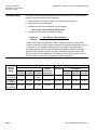
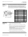
Technical Instructions
Document No. 155-029P25
AP 331-3
December 3, 2004
POWERS™ Controls
No. 6 Pneumatic Damper Actuator
331-2793 Actuator
331-2857 Actuator
with Clevis and Pin
331-3012 Extended Shaft and Frame
Mounting
Description
The POWERS Controls No. 6 Pneumatic Damper Actuator is a heavy-duty, rolling
diaphragm, spring return actuator designed to drive large dampers, centrifugal
refrigeration inlet vanes, and other applications requiring a large, effective diaphragm
area and long stroke.
Features
•
All metal body construction
•
Replaceable ozone-resistant, silicone rubber, rolling diaphragm
•
Pivot mounting for extended shaft or frame mounting
•
Positioning relay (optional)
•
Adjustable forward travel stops (optional)
•
Three spring ranges for sequencing with other control devices
Product Numbers
Application
See Table 1.
The No. 6 Pneumatic Damper Actuator controls outdoor, return air, exhaust, face and
bypass, and fan discharge dampers. It is recommended for heavy-duty applications
using multi-section dampers where either unison or sequence operation is required.
Certain actuators in Table 1 are UL Recognized Components for
fire/smoke applications under category EMKU2. This category covers
pneumatic damper actuators used on fire dampers and leakage rated
dampers.
Siemens Building Technologies, Inc.
Technical Instructions
Document No. 155-029P25
December 3, 2004
POWERS™ Controls No. 6 Pneumatic Damper Actuator
Table 1. Product Numbers for No. 6 Pneumatic Damper Actuators.
Product Numbers
Nominal Spring Range
Description
Mounting Style
Actuator, integral pivot
3-8 psi
(21-55 kPa)
3-13 psi
(21-90 kPa)
8-13 psi
(55-90 kPa)
1
Pivot
331-2793
331-2794
331-3060
Actuator, integral pivot and forward travel stops (Figure Pivot
1)
—
331-2796
331-2988
331-2858
331-28561
Actuator with clevis for frame mounting (Figure 2) or
remote extended shaft mounting (Figure 3)
Pivot2
331-2857
Actuator with clevis and positioning relay (Figure 16)
Pivot
2
—
Actuator, integral pivot with pivot post
3
Actuator, integral pivot with pivot post and positioning
relay3 (Figure 16)
1
2
3
Extended Shaft
Extended Shaft with
Positioning Relay
331-3012
—
—
331-3013
—
332-2856
331-30111
332-3011
UL Recognized Components for Fire/Smoke Applications.
Also order frame mounting kit accessories.
Mounted on plate for extended shaft with clevis and crank for 3/8-inch (10-mm), 7/16-inch (11-mm), or 1/2-inch
(13-mm) diameter shaft. Parts for frame mounting (blade drive) included with kit.
NOTE:
When the actuator is ordered with universal mounting, the mounting plate, pivot post and hardware, clevis,
damper crank, rocker arm, and all screws/nuts are included. Order other frame mounting accessories as
required, if not supplied by damper manufacturer.
Specifications
Effective diaphragm area
Stroke
Housing
Stem
Diaphragm
Spring
Bearing
Maximum air pressure
Nominal spring ranges
Ambient temperature range
Operation
Air connection
Type of mounting
Thrust and torque rating
Dimensions
Shipping Weight
Agency Approvals
Page 2
17.9 inches2 (115 cm2)
4 inch (102 mm)
Aluminum
Type 416 stainless steel
Ozone-resistant silicone rubber
Steel
Bronze oilite
30 psig (210 kPa)
3 to 8 psi (21 to 55 kPa)
3 to 13 psi (21 to 90 kPa)
8 to 13 psi (55 to 90 kPa)
-20°F to 200°F (-29°C to 93°C)
1/8-inch NPT
Pivot, universal (extended shaft or
frame mount)
See Table 2
See Figure 13 through Figure 16
9 lb (4.08 kg)
Complies with UL555 and UL555S
Siemens Building Technologies, Inc.
POWERS™ Controls No. 6 Pneumatic Damper Actuator
Accessories
Service Kits
Technical Instructions
Document No. 155-029P25
December 3, 2004
Damper shaft extension kits:
1/2-inch (13-mm) diameter, 2-1/4 inch (57-mm) rod
(See TB-128 POWERS™ Controls Damper Shaft Extension
Technical Bulletin 155-205P25)
1/2-inch (13-mm) diameter, 9-inch (229-mm) long hollow rod
1/2-inch (13-mm) diameter, 9-inch (229-mm) long rod
1–inch (25–mm) diameter 11-5/8 inch (295-mm) long (Ruskin)
Damper shaft extension kit adapter - 3/8 inch (10 mm) diameter
(for use with Damper Shaft Extension Kit 333-042)
Actuator shaft extensions:
10-1/8 inch (257-mm) long
Adapter kit for 1/2-inch NPT pipe
Cranks - damper shaft:
3/8-inch (10-mm) - 1/2-inch (13-mm) diameter,
Selectable radius
5/8-inch (16-mm) diameter
3/4-inch (19-mm) diameter
1-inch (25-mm) diameter
Cast iron crank with set screws
Linkage kit, 4-inch (102-mm) link and crank
Universal mounting plate
3/4-inch shaft
1-inch shaft (use with 333-194)
Flange bearing (1/2 inch, 13 mm)
(for 331-623 Universal Mounting Plate)
Right angle mounting plate
Remote mounting kit (extended shaft), Figure 3
Positioning relay
Positioning relay mounting kit
Frame mounting kits
One-section damper (Figure 5)
Two-section damper (Figure 6)
* Order frame mounting kits and damper blade clip kit from
Arrow United Industries.
Frame mounting lug
Mounting lug screws (three required for frame mounting lug)
Offset Mounting Bracket (Figure 14)
Travel Stop Kit (for model 3 and 4 actuators only)
Damper Blade Rocker Arm
Screws (two)
Nuts (two)
Silicone diaphragms (package of five)
Siemens Building Technologies, Inc.
331-631
333-184
333-042
333–194
331-632
331-434A
333-030
331-941
333-182
333-183
333-181
333-078
331-958
331-623
331-623A
331-862
333-208
331-618
147-2000
147-276
751*
752*
331-569
034-123K
333-176
333-197
333-034
030 510J
041-230J
333-572
Page 3
Technical Instructions
Document No. 155-029P25
December 3, 2004
Actuator Sizing
POWERS™ Controls No. 6 Pneumatic Damper Actuator
The quantity of actuators required depends on several torque factors. To determine the
quantity of actuators required for the installation:
1. Obtain damper torque ratings (ft-lb/ft2) from the damper manufacturer.
2. Determine the area of the damper.
3. Calculate the total torque required to move the damper:
Total Torque = Torque Rating x Damper Area
4. Calculate the total quantity of actuators required:
Number of
=
Actuators
1
Total Damper Torque Required
SF1 × Actuator Torque (see Table 2)
Safety Factor: When calculating the number of actuators required, a safety factor
should be included for unaccountable variables such as slight misalignments, aging of
the damper, etc. A suggested safety factor is 0.80 (or 80% of the rated torque).
See AB-300 Damper Actuator Sizing and Selection Application Bulletin in the HVAC
Systems/Controls Reference Data (125-1853) for additional sizing information. See
TB-181 Powers™ Controls Maximum Thrust Ratings of Pneumatic Damper Actuators
Technical Bulletin (155-219P25) for additional torque requirements.
Table 2. Thrust and Torque Rating.
Nominal
Spring
Range
Maximum Thrust lb. (N)
Full Stroke Forward
Spring
Return
(No Stroke)
15psi
18 psi
25 psi
(103 kPa) (124 kPa) (172 kPa) 0 psi (0 kPa)
Torque Rating* lb-in (Nm)
2-Position Operation
Gradual
or Positioner
Operation
15 psi
18 psi
25 psi
(103 kPa) (124 kPa) (172 kPa)
50 (5.6)
75 (8.5)
75 (8.5)
75 (8.5)
3-8 psi
(21-55 kPa)
125 (556)
179 (796)
304
(1352)
54 (240)
3-13 psi
(21-90 kPa)
36 (160)
89 (396)
214 (952)
54 (240)
50 (5.6)
8-13 psi
36 (160)
89 (396) 214 (952)
144 (640)
(55-90 kPa)
* With maximum hysteresis of 2.5 psi (17.2 kPa) @ 90° rotation.
50 (5.6)
Page 4
75 (8.5)
75 (8.5)
75 (8.5)
202 (22.8) 202 (22.8) 202 (22.8)
Siemens Building Technologies, Inc.
POWERS™ Controls No. 6 Pneumatic Damper Actuator
Operation
Standard Actuator
(Figure 1)
Technical Instructions
Document No. 155-029P25
December 3, 2004
The air tubing from a controlling instrument is connected to the actuator’s upper housing.
With no control pressure to the actuator, the compression spring forces the spring seat
and actuator shaft toward the upper housing, but is limited by the E-ring. As the control
pressure increases, the spring compression is overcome and the actuator shaft
gradually moves outward. Conversely, as control pressure decreases, the spring returns
the shaft to the position at which the air pressure on the diaphragm balances the spring
tension. For each value of control pressure there is a corresponding position of the shaft.
Table 3. Standard Actuator Components.
Figure 1. Standard Actuator.
Extended Shaft
Mounting—Pivot
Actuator
Item
Part No.
Description
Qty.
Material
1
047-061J
Retaining E-ring
1
Steel
2
333-217
1 × 1-1/4 in. Hex Nut
1
Brass
3
—
Spring Retainer
1
—
4
—
Stem Guide Assembly
1
—
5
—
Lower Housing
1
Aluminum
6
333-572
(pkg. of 5)
Diaphragm
1
Silicone
rubber
7
599-00413
5/16 in.-18 × 1
Large Hex Cap Screw
6
Steel
8
—
Upper Housing
1
Aluminum
—
Helical Compression Spring
1
9
331-091
3 to 13 psi (21 to 90 kPa)
—
331-208
3 to 8 psi (21 to 55 kPa)
—
331-094
8 to 13 psi (55 to 90 kPa)
—
10
—
Piston Plate and Stem
Assembly
1
Aluminum/
SS
11
—
Retaining C-ring
1
Steel
12
333-197
Stop Kit (Optional)
—
Steel
1. Order one of the following and see Table 4 for parts lists:
Actuator: 331-3011, 331,-3012, 331-3013, or 332-3011
2. Slip the 3/4-inch (19-mm) diameter hole in the mounting plate over the damper
shaft.
3. Slip the crank over the damper shaft. With the actuator assembly to the left of the
damper shaft, an increase in actuator pressure rotates the damper blade CW
when the crank is above the damper shaft, or CCW when the crank is below the
damper shaft. See Figure 2.
With the actuator assembly to the right of the damper shaft, an increase in
actuator pressure rotates the damper blade CCW when the crank is above the
damper shaft or CW when the crank is below the damper shaft.
4. Position the mounting plate and attach it to the duct with four screws.
5. When the actuator cannot be directly mounted, drive the extended damper shaft
using the Remote Mounting Kit 331-618 and Actuator 331-2856. See Figure 3.
Siemens Building Technologies, Inc.
Page 5
Technical Instructions
Document No. 155-029P25
December 3, 2004
POWERS™ Controls No. 6 Pneumatic Damper Actuator
Table 4. Extended Shaft/Frame Mounting Assemblies Components.
Item
Part No.
Description
Qty.
Material
1
041-162J
Nut
1
Steel
2
046-020K
Lockwasher
1
Steel
3
047-061K
Retaining E-ring
2
Steel
4
331-565
Pivot Post
1
Steel
5
041-142
Nut
1
Steel
6
333-207
Clevis
1
Zinc Plated Steel
7
331-293
Clevis Pin
1
Zinc Plated Steel
8
331-807
Hitch Pin
1
Zinc Plated Steel
9
331-941
Crank Assembly
1
—
10
331-623
Actuator Mounting Plate
1
Steel
—
034-283
Mounting Screws
4
Steel
Figure 2. Extended Shaft/Frame Mounting Actuator Assembly.
Figure 3. Remote Mounting Kit 331-618 with 331-2856 Actuator Mounted.
Frame Mounting Type A
Page 6
Order one each of the following. See Table 4 for parts lists:
Actuator and Clevis: 331-2856, 331-2857, or 331-2858
Frame Mounting Kit: 751 for one-section damper, or 752 for two-section damper
All frame mounting kits must be ordered from Arrow United Industries.
Siemens Building Technologies, Inc.
POWERS™ Controls No. 6 Pneumatic Damper Actuator
One-Section Damper
Kit 751
See Figure 4 and
Figure 5
Technical Instructions
Document No. 155-029P25
December 3, 2004
1. Attach the damper mounting bracket to the lower right-hand corner (or upper
left-hand corner if necessary) of the damper section with the six screws provided.
For Arrow United Industries 1770 dampers, add the shim provided between the
bracket and bottom of the frame. Have the damper manufacturer drill the holes in the
damper frame (Figure 5).
2. Have the damper manufacturer drill the holes in the damper blade for the blade clips
(Figure 4). Use the same clip location for both normally open and normally closed
dampers. Attach the damper blade clip to the damper blade (Figure 4). Put the
damper in its normal position, open or closed. Connect the push rod to the trunnion
in the blade clip and tighten the setscrew. Connect the other end of the push rod to
the crank on the drive shaft and tighten the trunnion setscrew on the push rod.
Position the crank so the push rod is parallel to the bracket, then tighten the crank
setscrews.
3. lnstall the actuator in the actuator support bracket using the pivot shaft and hitch
pins. The pivot shaft should be in the holes about 17-1/2 inch (445 mm) from the
drive shaft. The actuator support bracket can also mount in the vertical position for
installations where space is limited.
Figure 4. Damper Blade Clip.
4. Position the crank driven by the actuator as follows:
a. Normally open damper: the crank is above the drive shaft.
b. Normally closed damper: the crank is below the drive shaft.
5. Connect the actuator clevis to the crank. Put the damper in its normal position, open
or closed. Stroke the actuator 1/4-inch (6 mm) with a hand pump, then tighten the
crank setscrews. This will ensure tight damper closure.
Figure 5. One-section Damper.
Siemens Building Technologies, Inc.
Page 7
Technical Instructions
Document No. 155-029P25
December 3, 2004
Frame Mounting Type A,
Continued
Two-Section Damper
Kit 752
POWERS™ Controls No. 6 Pneumatic Damper Actuator
1. Follow the steps in One-Section Damper.
2. Attach the Damper Blade Clip to the damper blade in the second damper section.
Repeat Step 2 in One-Section Damper. The push rod will connect to the extra crank
on the drive shaft.
See Figure 6 and
Figure 7
Figure 6. Two-section Damper.
Figure 7. Actuator and Clevis Assembly 331-2857 (Typical)
Attached to Frame Mounting Kit 752.
Dimensions in Inches (Millimeters).
Page 8
Siemens Building Technologies, Inc.
POWERS™ Controls No. 6 Pneumatic Damper Actuator
Technical Instructions
Document No. 155-029P25
December 3, 2004
Frame Mounting Type B
1. Order one each of the following:
Actuator assembly: 331-3011, 331-3012, 331-3013, or 332-3011
Mounting Lug: 331-569
See Figure 8 through
Figure 10
2. Weld the mounting lug parallel and 5/16-inch (8 mm) from the inside edge of the
damper frame and perpendicular to it. See Figure 8. Weld the lug along both sides.
The lug should be as close as possible to the corner of the damper frame to
minimize deflection. The damper manufacturer should weld the lug.
Figure 8. Frame Mounting—Type B.
Dimensions in Inches (Millimeters).
3. If the damper frame is aluminum, light gauge sheet metal, or an unusual shape, bolt
a 3/16-inch (5-mm) thick, flat piece of steel to the frame. Then weld the mounting lug
to it.
4. Attach Rocker 333-034 to blade in proper position for normally open or normally
closed damper using 2 nuts, 041-230K, and 2 screws, 030-510J. See Figure 9 and
Figure 10.
5. Attach the mounting plate to the mounting lug as follows:
a. Normally Open damper: attach the plate to the lug. Place the pivot post in Hole
4. See Figure 9.
b. Normally Closed damper: attach the plate to the lug. Place the pivot post in Hole
3. See Figure 10.
6. Fasten the clevis to the rocker. Discard the crank and other parts not used.
7. The actuator mounting plate has a tendency to pivot at the point where the lug is
welded to the damper frame when the actuator strokes. It is recommended that
some means be devised in the field to prevent this from happening. A threaded rod
attached to the mounting plate and duct wall will normally work.
Siemens Building Technologies, Inc.
Page 9
Technical Instructions
Document No. 155-029P25
December 3, 2004
POWERS™ Controls No. 6 Pneumatic Damper Actuator
Frame Mounting - Type B, Continued
Figure 9. Frame Mounting,
Normally Open Damper.
Figure 10. Frame Mounting,
Normally Closed Damper.
Actuator Mounting
Table 5. Mounting Plate Hole Identification.
Hole
1
Used For
No. 6 Actuator extended shaft
mounting.
2
Not used.
3
No. 4 Actuator extended shaft.
No. 6 Actuator frame mounting NC
4
No. 6 Actuator frame mounting NO
5
No. 4 Actuator frame mounting NC
6
No. 4 Actuator frame mounting NO
Figure 11. Actuator Mounting Plate 331-623
Pivot Shaft Locations.
Dimensions in Inches (Millimeters).
Table 6. Pivot Post Hole Identification.
Figure 12. Actuator Mounting Plate 331-623A
Pivot Shaft Locations.
Page 10
Hole
Used For
1
2
3
No. 6 Actuator extended shaft mounting
Not used
No. 4 Actuator extended shaft
4
5
No. 6 Actuator frame mounting NC
No. 6 Actuator frame mounting NO
No. 4 Actuator frame mounting NC
6
No. 4 Actuator frame mounting NO
Siemens Building Technologies, Inc.
POWERS™ Controls No. 6 Pneumatic Damper Actuator
Technical Instructions
Document No. 155-029P25
December 3, 2004
Dimensions
Figure 13. Extended Shaft Remote Mounting with Travel Stops.
Dimensions in Inches (Millimeters).
Offset Mounting
Bracket
This bracket is
designed to offset
Universal Mounting
Plate 331-623 or
331-623A from the
ductwork.
NOTE: Depending on
the application, two
brackets may be
required to support
the actuator and
universal mounting
plate.
Siemens Building Technologies, Inc.
Figure 14. Offset Mounting Bracket 333-176.
Dimensions in Inches (Millimeters).
Page 11
Technical Instructions
Document No. 155-029P25
December 3, 2004
POWERS™ Controls No. 6 Pneumatic Damper Actuator
Dimensions,
Continued
Figure 15. Actuator Mounting Plate 331-623.
Dimensions in Inches (Millimeters).
Figure 16. No. 6 Actuator with the
RL 147 Positioning Relay Mounting.
Dimensions in Inches (Millimeters).
Information in this publication is based on current specifications. The company reserves the right to make changes in specifications and models as
design improvements are introduced. POWERS is a trademark of Siemens Building Technologies, Inc. Other product or company names
mentioned herein may be the trademarks of their respective owners. © 2004 Siemens Building Technologies, Inc.
Siemens Building Technologies, Inc.
1000 Deerfield Parkway
Buffalo Grove, IL 60089-4513
U.S.A.
Your feedback is important to us. If you have
comments about this document, please send
them to [email protected]
Document No. 155-029P25
Country or Origin: US
Page 12