1
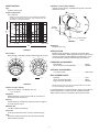
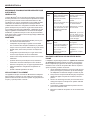
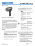
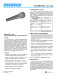
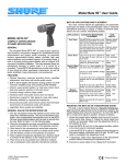
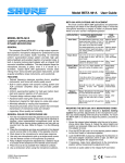
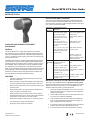
Model BETA 52®A User Guide
MODEL BETA 52®A
APPLICATIONS AND PLACEMENT
The most common BETA 52A applications and placement techniques are listed in the following table. Keep in mind that microphone technique is largely a matter of personal taste– there is no
one “correct” microphone position.
Application Suggested Microphone
Placement
Kick Drum
5 to 7.5 cm (2 to 3 in.) away
from beater head, slightly
off-center from beater.
SUPERCARDIOID DYNAMIC INSTRUMENT
MICROPHONE
GENERAL
The Shure BETA 52®A is a high output dynamic microphone
with a tailored frequency response designed specifically for kick
drums and other bass instruments. It provides superb attack and
“punch,” and delivers studio quality sound even at extremely high
sound pressure levels.
The BETA 52A features a modified supercardioid pattern throughout its frequency range to insure high gain before feedback and
excellent rejection of unwanted sound. A built–in dynamic locking
stand adapter with an integral XLR connector simplifies installation, particularly if the microphone is to be placed inside a kick
drum. The stand adapter keeps the microphone position fixed and
resists slipping, even when subjected to sharp blows and strong
vibrations. A hardened steel mesh grille protects the BETA 52A
from the abuse and wear associated with touring.
FEATURES
Tone Quality
Sharp attack; maximum
bass sound, highest sound
pressure level.
20 to 30 cm (8 to 12 in.)
from beater head, on-axis
with beater.
Medium attack; balanced
sound.
20 to 30 cm (8 to 12 in.)
from beater head, 15 to 20
cm (6 to 8 in.) from edge
of head.
Medium attack; thin, reduced bass sound.
5 to 7.5 cm (2 to 3 in.) away Softer attack; balanced,
from outside head, on-axis resonant sound.
with beater (double head
kickdrum only).
NOTE: To “tighten” the
beat, place a pillow or
blanket on bottom of drum
against beater head.
Electric
2.5 cm (1 in.) from speaker,
Bass Ampli- on-axis with center of
fier
speaker cone.
2.5 cm (1 in.) from speaker,
at edge of speaker cone.
Sharp attack; emphasized
bass.
Sharp attack; higher frequency sound.
10 to 15 cm (4 to 6 in.) from Sharp attack; full, balanced
speaker, on-axis with center sound.
of speaker cone.
60 to 90 cm (2 to 3 ft.) from Soft attack; mellow, higher
speaker, on-axis with center frequency sound.
of speaker cone.
•
Frequency response shaped specifically for kick drums
and bass instruments
•
Built–in dynamic locking stand adapter with integral XLR
connector simplifies setup, especially inside a kick drum
•
Studio quality performance, even at extremely high sound
pressure levels
•
Supercardioid pattern for high gain before feedback and
superior rejection of unwanted noise
•
Hardened steel mesh grille that resists wear and abuse
1. Screw the integral stand adapter onto the end of a microphone stand (see Figure 3). Adjust the stand height and
position as necessary.
•
Advanced pneumatic shock mount system that minimizes
transmission of mechanical noise and vibration
2. Pivot the BETA 52A until it is in the desired position relative to the drum head or loudspeaker.
•
Neodymium magnet for high signal–to–noise ratio output
•
Low sensitivity to varying load impedance
•
Legendary Shure quality and reliability
3. Lock the BETA 52A in place by rotating the adjustment
knob on the stand adapter clockwise until it is tight. Do
NOT overtighten the knob with tools.
MOUNTING THE BETA 52A ON A MICROPHONE STAND
The built–in stand adapter features a dynamic locking system
that permits adjustments to the microphone’s position, but resists
slipping when struck or bumped. To mount the BETA 52A on a
stand and adjust its position, proceed as follows:
4. If necessary, make minor adjustments to the microphone
position without loosening the adjustment knob.
5. Connect an audio cable to the integral XLR connector.
27D2799 (Rev. 5)
©2005, Shure Incorporated
Printed in U.S.A.
SPECIFICATIONS
Adjustable, Locking Stand Adapter
Integral, dynamic locking, adjustable through 180°, with standard 5/8”-27 thread
Type
Dynamic (moving coil)
Frequency Response
20 to 10,000 Hz
4.451
NOTE: The curve below shows on–axis response at a distance
of 2 feet from a uniform sound source. Your response may vary,
depending on microphone position
+20
3 mm
(1/8 in.)
51 mm
(2 in.)
dB
180
6.406
3.750
STAND
ADAPTER
25 mm
(1 in.)
+10
ADJUSTMENT
KNOB
0
.06 m
(2 ft)
–10
MICROPHONE
STAND
-20
2
20
50 100
3 4 5 6 7 89
1000
2
FIGURE 3
3 4 5 6 7 89
10000 20000
Net Weight
605 grams (21.6 oz)
Hz
FIGURE 1
CERTIFICATION
Eligible to bear CE Marking. Conforms to European EMC
Directive 89/336/EEC. Meets applicable tests and performance
criteria in European Standard EN55103 (1996) parts 1 and 2,
for residential (E1) and light industrial (E2) environments.
Polar Pattern
Supercardioid, rotationally symmetrical about microphone axis
180°
180°
150°
150°
150°
120°
120°
90°
90°
Storage Bag . . . . . . . . . . . . . . . . . . . . . . . . . . . . . .26A25
5/8” to 3/8” (Euro) Thread Adapter . . . . . . . . . . . .95A2050
90°
90°
–20 dB
–20 dB
–15 dB
–10 dB
FURNISHED ACCESSORIES
120°
120°
–15 dB
60°
60°
150°
OPTIONAL ACCESSORIES
60°
60°
–10 dB
–5 dB
7.6 m (25 ft) Cable . . . . . . . . . . . . . . . . . . . . . . . . .C25E, C25F
–5 dB
30°
30°
30°
30°
0
REPLACEMENT PARTS
0
250 Hz
Cartridge . . . . . . . . . . . . . . . . . . . . . . . . . . . . . . . .R175
Screen and Grille Assembly . . . . . . . . . . . . . . . . .RK321
Plug (connector) Assembly . . . . . . . . . . . . . . . . . .90F1984
2500 Hz
500 Hz
1000 Hz
FIGURE 2
NOTE: Use care when removing the cartridge holder from the base
to prevent breakage of the lead wires.
Output Level (at 1,000 Hz)
Open Circuit Voltage: –64 dBV/Pa* (0.6 mV)
For additional Service or parts information, please contact Shure’s
Service department at 1–800–516–2525. Outside the United
States, please contact your authorized Shure Service Center.
*1 Pa = 94 dB SPL
Impedance
Rated impedance is 150 Ω (45 Ω actual) for connection to
microphone inputs rated low Z
Phasing
Positive pressure on diaphragm produces positive voltage on
pin 2 with respect to pin 3
Maximum SPL
174 dB at 1000 Hz (calculated)
Connector
Three–pin professional audio connector (male XLR type)
Case
Silver blue enamel–painted die cast metal with hardened,
matte-finished steel grille
2
MODÈLE BETA 52®A
MICROPHONE DYNAMIQUE SUPERCARDIOÏDE POUR
INSTRUMENTS
GÉNÉRALITÉS
Application Placement Suggéré
Sonorit
Grosse
caisse
5 à 7,5 cm de la peau de
frappe, légèrement décalé
par rapport à la batte.
Attaque franche, basse
maximum, pression acoustique maximum.
20 à 30 cm de la batte,
dans son axe.
Attaque moyenne, son
équilibré.
Le Shure BETA 52®A est un microphone dynamique à haut niveau
de sortie présentant une courbe de réponse spécialement étudiée
pour les grosses–caisses et autres instruments basse. Il offre
une attaque et un ”punch” exceptionnels et une qualité de studio,
même dans des conditions de pression acoustique extrême.
20 à 30 cm de la batte, 20 à Attaque moyenne, petit
30 cm du cerclage.
son, basses réduites.
Le BETA 52A maintient une configuration cardioïde dans toute sa
gamme de fréquences pour assurer un gain élevé avant Larsen
et un excellent rejet des bruits indésirables. L’adaptateur de pied
intégral, réglable et verrouillable avec connecteur XLR simplifie
l’installation, en particulier lorsque le micro est placé à l’intérieur
de la grosse caisse. La grille en acier trempé protège le BETA 52A
des rigueurs des tournées.
5 to 7.5 cm (2 to 3 in.) away Attaque douce, son équilifrom outside head, on-axis bré et résonnant.
with beater (double head
kickdrum only).
REMARQUE : pour un son
plus ”net” placer un coussin ou une couverture dans
le bas de la caisse, contre
la peau de frappe
AVANTAGES
•
Courbe de réponse spécialement étudiée pour les grosses–caisses et instruments basse.
•
L’adaptateur de pied intégral, réglable et verrouillable
avec connecteur XLR simplifie l’installation, en particulier
lorsque le micro est placé à l’intérieur de la grosse caisse.
•
Qualité studio, même à des pressions acoustiques élevées.
•
Configuration supercardioïde pour un gain élevé avant
Larsen et rejet supérieur des bruits indésirables.
•
Grille en acier trempé résistante à l’usure et aux mauvais
traitements.
MONTAGE DU BETA 52A SUR UN PIED DE MICROPHONE
•
Système antichocs pneumatique avancé, réduisant la
transmission des bruits mécaniques et des vibrations.
•
Aimant au néodymium pour un rapport signal/bruit élevé.
•
Faible sensibilité aux changements d’impédance de
charge.
L’adaptateur de pied intégré présente un système de verrouillage dynamique permettant d’ajuster la position du microphone
tout en empêchant qu’il glisse s’il est heurte’ par les baguettes
du batteur. Pour monter le microphone BET 52A sur un pied et
ajuster la position, procéder comme suit :
•
Qualité et fiabilité légendaires de Shure.
Amplis de
basse
électrique
2,5 cm du haut–parleur, au
centre.
Attaque franche, dominance graves.
2,5 cm du haut–parleur, sur
le bord de la membrane.
Attaque franche, son plus
aigu.
10 à 15 cm du haut–parleur, au centre.
Attaque franche, son plein
et équilibré.
60 à 90 cm du haut–parleur, au centre.
Attaque douce, son plus
aigu.
1. Visser l’adaptateur intégré sur le haut d’un pied de microphone (voir la figure 3). S’assurer que la vis de blocage
de l’adaptateur est desserrée. Régler a hauteur du pied.
APPLICATIONS ET PLACEMENT
Les applications les plus courantes du BETA 52A sont indiquées
dans le tableau ci–dessous. Ne pas oublier que la technique de
placement des micros est surtout une question de goût personnel
et qu’il n’y a pas de position ”correcte”.
2. Faire pivoter le microphone BETA 52A jusqu’a la position
désirée par rapport a la peau de la caisse ou au haut–
parleur.
3. Serrer la vis de blocage a la main (en la tournant vers la
droite) pour bloquer le microphone en position. NE PAS
serrer la vis en excès.
4. Si nécessaire, modifier légèrement la position du microphone sans desserrer la vis.
5. Brancher un câble de microphone sur le connecteur XLR
intégré.
3
CARACTÉRISTIQUES
Adaptateur de pied réglable, verrouillable
Intégral, à emboîtement, verrouillable, réglable à travers 180.
avec filet standard de 5/8”–27
Type
Dynamique (bobine mobile)
Courbe de réponse
20 à 10 000 Hz
4.451
REMARQUE : la courbe ci–dessous montre la réponse en axe à
une distance de 60 cm d’une source sonore uniforme. La courbe de
réponse peut varier en fonction du placement du microphone.
+20
51 mm
(2 in.)
dB
3.750
ADAPTATEUR
DE PIED
25 mm
(1 in.)
+10
180
6.406
3 mm
(1/8 in.)
VIS DE
0
BLOCAGE
.06 m
(2 ft)
–10
PIED
-20
2
20
50 100
3 4 5 6 7 89
1000
2
FIGURE 3
3 4 5 6 7 89
10000 20000
Poids net
605 grammes
Hz
FIGURE 1
HOMOLOGATION
Autorisé à porter la marque CE. Conforme à la directive CEM
européenne 89/336/CEE. Conforme aux critères applicables
de test et de performances de la norme européenne EN 55103
(1996) parties 1 et 2 pour les environnements résidentiels (E1) et
d’industrie légère (E2).
Courbe de directivité
Supercardioïde, rotativement symétrique autour de l’axe du
microphone
180°
180°
150°
150°
150°
120°
120°
90°
90°
Étui de rangement . . . . . . . . . . . . . . . . . . . . . . . . .26A25
Adaptateur de filet 5/8 à 3/8 po. (Europe). . . . . . .95A2050
90°
90°
–20 dB
–15 dB
–15 dB
–10 dB
ACCESSOIRES FOURNIS
120°
120°
–20 dB
60°
60°
150°
ACCESSOIRES EN OPTION
Câble de 7,6 m . . . . . . . . . . . . . . . . . . . . . . . . . . .C25E, C25F
60°
60°
PIÈCES DE RECHANGE
–10 dB
–5 dB
–5 dB
30°
30°
Cartouche . . . . . . . . . . . . . . . . . . . . . . . . . . . . . . .R175
Grille . . . . . . . . . . . . . . . . . . . . . . . . . . . . . . . . . . . .RK321
Prise (connecteur) . . . . . . . . . . . . . . . . . . . . . . . . .90F1984
30°
30°
0
0
250 Hz
2500 Hz
500 Hz
1000 Hz
Pour plus de détails sur les réparations ou les pièces, contacter
le service Entretien Shure au 1–800–516–2525. À l’extérieur des
États–Unis, contacter le centre de réparations Shure agréé.
FIGURE 2
Niveau de sortie (à 1000 Hz)
Tension en circuit ouvert : –64 dBV/Pa* (0,6 mV)
*1 Pa = 94 dB SPL
Impédance
L’impédance nominale est de 150 Ω (45 Ω réelle) pour connexion aux entrées de micros basse impédance.
Phase
Une pression positive sur le diaphragme produit une tension
positive sur la broche 2 par rapport à la broche 3.
Pression acoustique maximum
174 dB à 1 000 Hz (calculée)
Connecteur
Connecteur professionnel 3 broches type XLR.
Corps
Fonte émaillé bleu argenté avec grille sphérique matte en acier
trempé.
4
SHURE Incorporated http://www.shure.com
United States, Canada, Latin America, Caribbean:
5800 W. Touhy Avenue, Niles, IL 60714-4608, U.S.A.
Phone: 847-600-2000 U.S. Fax: 847-600-1212 Int’l Fax: 847-600-6446
Europe, Middle East, Africa:
Shure Europe GmbH, Phone: 49-7131-72140 Fax: 49-7131-721414
Asia, Pacific:
Shure Asia Limited, Phone: 852-2893-4290 Fax: 852-2893-4055