1
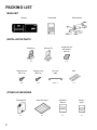
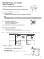
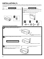
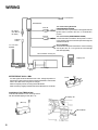
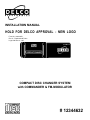
INSTALLATION MANUAL
HOLD FOR DELCO APPROVAL - NEW LOGO
Form No. 128-4487A
Rev. A - Replaced old Delco
Logo with New. 2-1-95.
COMPACT DISC CHANGER SYSTEM
with COMMANDER & FM-MODULATOR
# 12344632
PACKING LIST
MAIN UNIT
Changer
FM Modulator
Commander
INSTALLATION PARTS
Bracket (L)
Bracket (R)
Hexagonal bolt
with washer
(M5 x 8)
x1
x1
x4
Tapping screw
(M5 x 12)
Tapping screw
(M3 x 12)
Din 8 pin
cable
Seal
x4
x2
5mx1
x1
OTHER ACCESSORIES
2
CD Magazine
Index seal sheet
Installation
Manual
Owner's
guide
x1
x1
x1
x1
BEFORE INSTALLING THE UNIT
Transport Lock Screws
The mechanism in the CD changer is "locked" into place during shipment by the
transport screws. Be sure to remove the screws prior to installation.
Caution
After removing the transport lock screws, place the supplied seals over the screw
holes. These seals are used to keep dust out of the unit, which could cause a malfunction.
Installation and Wiring Precautions
1
To prevent a short-circuit,
Be sure to turn off the ignition and remove the negative (-) battery cable, prior to installation.
Connect power wires last.
Note
If the changer is to be installed in a car that is equipped with an on-board drive or navigation computer, do not disconnect the battery
cable. If the cable is disconnected, the computer memory may be lost. Under these conditions, use extra caution during installation,
not to cause a short circuit.
2
Do not install the unit in the following locations.
Locations exposed to direct sunlight.
Where hot air is discharged from the car heater.
In areas subject to extreme temperatures.
3
Incorrect installation can cause the sound to "skip" when playing a disc.
Mount the unit firmly in place, using the supplied brackets and screws.
4
5
Be careful not to damage the car wiring.
6
Be sure to use the supplied screws.
Be careful not to snag any wires when tightening screws.
Do not use any of the screws that are part of the brake or steering system, to install the unit.
Install the unit as closely to vertically or horizontally as possible. If the unit must be inclined, the angle must be 15° or less.
Installation and inclination angle
Vertical mounting
Horizontal mounting
Installation
15° max.
15° max.
Angle
7
ID (Identity) Switch for 2nd CD Changer
When used with a compatible controller, an additional CD changer can be installed.
When an additional CD changer has been attached in this fashion, the ID switch is
used to indicate the number of each respective changer unit.
Changer Identity Switch
Do not use this switch if only 1 CD changer is being used.
Refer to the manual of the divider unit for further details on 2 changer operation.
Changer Identity Switch
3
INSTALLATION (1)
The unit can be installed vertically or horizontally. The position of the built-in anti-vibration springs (left and right side), must correspond
to the mounting position chosen. If the springs are not set correctly for the type of installation chosen, the anti-vibration compensation will
not be effective.
Horizontal Installation
Note
The unit is shipped with the springs installed for horizontal installation.
Vertical Installation
It is necessary to change the spring attachment position.
1) Remove the lock screws on the side of the set using a Phillips
screwdriver.
2) Turn the spring attachment to the (V) mark side using a screwdriver.
3) Replace the removed screws on the (V) mark side.
1
1
2
3
Procedure for Horizontal Installation
1
Attach bracket (L) and bracket (R) to each side of the unit,
using the hexagonal bolts with washer base (M5 x 8).
Hexagonal bolt with washer base
(M5 x 8)
2
Determine the mounting location, and drill four mounting
holes.
Never mount the unit near the fuel tank.
Drill holes 4mm in diameter.
3
Secure the unit in place, using four self-tapping screws
(M5 x 12).
Use RTV (silicone sealer) on screw threads or around
the holes to prevent moisture intrusion.
Self-tapping screw (M5 x 12)
Bracket (R)
4
INSTALLATION (2)
Procedure for Vertical Installation
Note
If the anti-vibration spring position has been changed and verified for vertical mounting (as shown on page 3), start with step 2.
1
It is necessary to change the spring attachment position.
1) Remove the lock screws on the side of the set using a
Phillips screwdriver.
2) Turn the spring attachment to the (V) mark side using a
screwdriver.
3) Replace the removed screws on the (V) mark side.
2
Attach bracket (L) and bracket (R) to each side of the unit,
using the hexagonal bolts with washer base (M5 x 8).
H
Bracket (R)
Hexagonal bolt
with washer base
3
Determine the mounting location, and drill four mounting
holes.
Never mount the unit near the fuel tank.
4
Mount the unit in place, using four self-tapping screws
(M5 x 12).
Use RTV (silicone sealer) on screw threads or around
the holes to prevent moisture intrusion.
Self-tapping screw
(M5 x 12)
Drill holes 4 mm in diameter.
Bracket (R)
5
WIRING
To car antenna
FM Modulator
Fuse 2A
RF output
(89.1MHz or
88.7MHz)
Fuse 5A
Antenna
socket
+12 volt Accessory/Switched
(ORANGE/WHITE STRIPE)
Connect this wire to a point which is energized when the
ignition switch is turned to the "ON" or "ACCESSORY"
position.
+12 volt Constant (GREEN/WHITE STRIPE)
Connect this lead to the cable to which power is continuously supplied and which has been passed through the
vehicle's fuse block.
Ground (BLACK)
Screw this to a metal part of the vehicle. Clean connecting
area of paint, dirt, etc. Poor ground can cause damage
and affect playability.
To +12V ACC,
Speaker
DIN connection cord (6 pin)
Display Unit
FM Radio
DIN cable
(8pin)
CD changer
INTERFERENCE ON 89.1 MHz
If a clear signal cannot be obtained on 89.1 MHz, change the position of
the frequency select switch on the back of the FM Modulator and tune the
radio to 88.7 MHz when using the CD changer.
Select a frequency before mounting the FM Modulator.
Radio sensitivity is slightly reduced when the FM Modulator is connected.
Driver
Installation of the FM Modulator:
Install the FM Modulator to the mounting surface
with the included tapping screws (M3 x 12).
Display unit
(M3 x 12)
FM Modulator
6
INSERT VEHICLE WIRING DIAGRAM
DWG. NO. 128-4487S
Features:
Shuffle Play
Conveniently shuffles the tracks on the disc selected, or entire 10 discs
giving the user a different concert mix every time.
Disc Select
Easily moves up (+) or down (-) discs with the disc select buttons.
Track Search
Advances to the next track on the disc or returns to the beginning of the
current track.
Track/Disc
Repeat
Repeat current track or disc. Allows user to play favorite CD or songs
over.
Track/Disc
Scan
Preview tracks and disc for 10 second per selection until you reach the
desired one.
Wired Remote
Eliminates the possibility of remote loss. Easy to locate. Conveniently
backlit.
Warranty
One year limited GM warranty.
Delco Electronics 10 Disc Changer Part #12344632
Also requires applicable antenna adapters listed:
All Geo's through 1995, Pre-1988 GM, most Domestic and Foreign Vehicles:
-No adapters required.
1988 - 1993 Vehicles with 12 Pin Radios:
-No adapters required.
1988 - 1993 Vehicles with 21 Pin Radios:
-Require the following adapters (one each):
GM Part # 16056152
GM Part # 16047347
1994 & 1995 Vehicles:
-Require the following adapters (one each):
GM Part # 16169591
GM Part # 16169611
For more information on the 10 Disc Changer,
please contact Delco Electronics at
1-800-428-0501
16213708
2/95