1
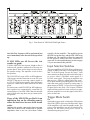
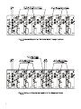
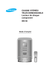
Sherbourn
Technologies, Inc.
Owner’s Manual for
Model LDS16-40
Power Amplifier
Thank you so much for your decision to purchase
one of our superb Sherbourn amplifiers. We take
enormous pride in the design and build quality of
all of our products and we are confident that our
product will provide you with many years of
enjoyable and trouble-free service. Should you have
any need to call upon our services please feel free
to contact us at the address shown at the end of
this booklet; or, of course, you can contact the
dealership from which you purchased the product.
Full details of the warranty coverage provided by
Sherbourn Technologies can be found at the end
of this booklet.
Safety Instructions
1. Important Safety Instructions! Please read
all the safety and operating instructions shown
in this manual before operating this equipment.
WARNING SHOCK HAZARD - DO NOT OPEN
AVIS RISQUE DE CHOC ELECTRONIQUE
-NE PAS OUVRIR
1. The lightening flash within an equilateral triangle
shown above is intended to alert you to the presence
of uninsulated ‘dangerous voltage’ within the
product’s enclosure that may be of sufficient
magnitude to constitute an electric shock.
3. The exclamation point within an equilateral
triangle shown above is intended to alert you to
the presence of important operating and
maintenance (servicing) instructions in the
literature accompanying this appliance.
4. Please retain this manual in a safe place for future
reference about safety and operating matters.
5. Adhere to all warnings and follow all operating
instructions.
6. Warning: To reduce the risk of fire or electrical
shock, do not expose this equipment to rain or
moisture.
There are no user serviceable parts inside. Refer
servicing to qualified personnel.
7. Caution: To prevent electrical shock do not use
this (polarized) plug with an extension cord,
receptacle or other outlet unless the blades can
be fully inserted to prevent blade exposure.
8. For added protection for this product during a
lightening storm or when it is left unattended and
unused for long periods of time, it is recommended
that you unplug the unit from the wall outlet. This
will prevent damage to the product due to
lightening or power line surges.
9. Do not use attachments not recommended in this
owner’s manual as they may cause hazards.
10. Locate the equipment for proper ventilation.
For example, the product should never be allowed
to operate while positioned on a bed, rug, sofa or
any such surface where proper ventilation is not
possible. Nor should the unit be placed in a builtin installation such as a cabinet or armoire, etc. in
such a way as to impede the air flow. Always ensure
adequate ventilation openings - please see later
comments regarding such an installation.
11. Locate the product away from heat sources such
as stoves, heat registers, radiators or other
appliances including other amplifiers that produce
heat.
12. Mount the equipment in a wall or cabinet only
as described in this owner’s manual.
13. Do not use the equipment near water; for
example near a bathtub, washbowl, kitchen sink, a
swimming pool, a wet basement, etc.
14. Do not place the product on an unstable cart,
stand tripod, bracket or table. The equipment is
heavy and should it fall, it could cause serious injury
to a person and/or serious damage to the equipment.
Caution for Installation
1. Your Sherbourn amplifier can be placed on any
table or shelf. It can also be custom installed in a
rack, and/or in a piece of cabinetry or furniture of
your choice. It is however, important that if the
amplifier is going to be housed in an enclosed
environment, that you allow for adequate
ventilation. Despite the adequately sized heatsinks
built into the amplifier, it is still important that good
ventilation be provided. Do not install the amplifier
directly above another heat generating component
such as another amplifier without adequate
ventilation.
1
2. If your amplifier is going to be placed in an
enclosed space such as an armoire, it is essential
that adequate ventilation be provided. We strongly
suggest that the shelf on which the product is being
placed includes a cutout of at least twenty inches
by twelve inches (50 cm by 30 cm) directly under
the ventilation slots on the bottom of the amplifier.
A similarly sized cutout should be made in the
upper or rear wall behind the shelf so that free air
can flow from beneath the unit to the outside
atmosphere. Also allow a minimum of three inches
(7.5 cm) free space above the product and two
inches (5 cm) on either side of the product. This
combination of space will allow for a free flow of
circulating air to help keep the amplifier from
overheating. If your cabinet includes a number of
products, it may be advisable to install a quiet fan
to assist the cooling process.
3. The dealership from which you purchased the
product is an expert on custom installation
procedures and can provide invaluable advice to
help you make an aesthetically pleasing and trouble
free installation.
Caution for Connections
1. Connect this equipment only to the type of AC
power source as marked on the unit. Always route
AC power cords so they are not likely to be walked
on, or tripped over, or where they may be pinched
by items placed on or against them. Always pay
particular attention to cords at plugs and/or
convenience receptacles, and at the point where
they exit from the product.
2. Do not defeat the inherent design features of the
polarized plug. Non polarized line cord adapters
will defeat the safety provided by the polarized AC
plug. If the plug should fail to fit, contact your
electrician to replace your obsolete outlet. Do not
defeat the safety purpose of the grounding-type
plug. If you use this product in a country which
only has two slotted receptacles in the house, you
must use a three-pin adapter plug to earth ground
which is the “E” (earth pin) of the power cord
connected to this product.
3. Do not overload wall outlets, extension or
integral convenience receptacles, as this could
result in a risk of fire or shock.
Operating Voltage
The LDS16-40 amplifier is factory-set for 110V/
120V 60 HZ or 230V 50HZ AC operation,
according to the country for which the unit was
manufactured (230V in European Union countries,
in compliance with CE regulations). The operating
2
voltage cannot be changed by the user and any
attempt to do so may risk of causing damage to the
amplifier and will void the warranty.
Care of the Product
Clean the product by dusting with a dry cloth. Do
not permit objects of any kind to be pushed and/or
fall into the product through the enclosure
openings.
Front Panel Description
The front panel houses the main Power ON/OFF
switch. A blue power LED will illuminate when
the LDS16-40 is ON and will dim when all zone
amplifiers are in the ‘Standby’ mode. The LED will
only extinguish when the Power ON/OFF switch
is in the OFF position or when the LDS16-40 is
disconnected from the electrical outlet.
Rear Panel Connections
The LDS16-40 has been designed to provide
multiple stereo zones with identical performance
and features. The following descriptions apply to
all zones.
The connections of the audio signal between your
preamp/control center and your LDS16-40 will be
made discretely via cables from the outputs of your
preamp to the gold plated inputs of your LDS1640. Please ensure that the cables are installed for
each channel as described on the following pages.
Volume Controls
Two separate controls are provided for left and right
volume control. When functioning under the
bridge-mono mode, only the right volume control
is used for volume adjustment.
LDS Operation
Each time the power comes on, the LDS16-40 will
perform the LDS (Load Detection System) test
sequence from zone-1 to the last zone amplifier.
Sherbourn’s LDS technology incorporated in this
product will automatically detect a short-circuit in
the speaker wiring and will also check for
speaker(s) that may be configured with too low an
impedance of less than 4 ohms typically. During
the test sequence, observe the rear panel LDS LEDs
for the following test results.
The power should be off during your
installation. Once your installation is complete
and the unit is powered up, the LDS16-40 will
automatically perform the LDS Test Sequence
described in the previous paragraph. Please note
Fig. 1. Rear Panel of LDS1640 With Eight Zones
that this Test Sequence will be performed just
once, immediately after the unit is first powered
up.
If LDS LEDs are all Green (the test
results are good)
If all the LDS LEDs are in green, bright or dim, it
indicates all speakers connected to the amp are
greater than 4 ohm, and no short-circuit exists in
the speaker wiring. The amplifier is safe to drive
the speakers.
The LDS LED of a zone will be in full brightness,
if the trigger switch of that zone is set to ON, or to
MUSIC if the amp is receiving a music signal, or
to 12V if a 12Vdc trigger input is fed to the trigger
input jack. Otherwise, it shall remain in low-level
green.
For those zones with LDS LED in full brightness,
their speakers are automatically connected (by
internal relays); if an LDS LED is dim, the internal
relay of that zone amp does not get connected to
the speaker.
If any of the LDS LEDs are Red it is an
indication that on the offending zone(s)
either the load is too low or a short circuit
exists.
Indicates the speaker connected to that zone amp
either has a short-circuit connection or speaker
impedance that is too low (less than 4 ohms
typically) for the amplifier. The amplifier repeats
the LDS test on that zone, and the LDS LED keeps
flashing red. The amplifier will not be connected
to the speaker unless the fault condition is
corrected. See the troubleshooting section on page
5 if you encountered this problem.
Input Selection Switches
The zone amplifiers of LDS16-40 are split into two
groups, A and B, with zone 1 to 4 being the A group
and 5 to 8 the B group. Except for zone 1, each
zone contains an input selection switch allowing it
to receive either a GLOBAL main signal or a
LOCAL zone signal. The group A amplifiers can
thus receive a Global-A signal (fed to the zone 1
RCA input) and the group-B amplifiers can receive
either the same group-A signal by setting zone 5’s
input selector to ZONE 1, or receive its own globalB signal (fed to the Zone 5 RCA input). With the
input selection switch of a zone set to its own zone,
the zone amplifiers receive the signal via the RCA
jacks of that zone.
Trigger Mode Switch
On
Setting the trigger mode switch to the ON position
allows the LDS16-40 to stay ON all the time. None
of the amplifiers will enter the standby mode. The
power to the amplifiers can only be turned off by
turning off the front panel power switch or
disconnecting the power cord.
3
Music
Setting a trigger mode switch to MUSIC position,
sets the LDS16-40 zone-amps into auto-onstandby power control mode. Each zone-amp can
sense, individually, a very low level music signal
fed to its signal input, which will turn the amplifier
into an active state and will play the music. When
the music stops and no further signal is received
for more than 10 minutes, the zone-amp will turn
into a standby mode, which cuts off the power
consumption substantially and the green LED will
become dim. The zone-amp will wake up from
the standby mode, or sleep mode, whenever the
zone receives a music signal again.
12V
Setting the trigger mode switch of a zone-amp to
12V allows the power-on-standby function of that
zone-amp to be controlled by a 12V DC voltage
connected to the 12V input jacks of group A and
group B amplifiers. When 12V DC is present at
the 12V trigger input jacks, the zone-amplifiers will
turn on, and when the 12V disappears, the zoneamps will enter the standby mode momentary.
Under standby mode, no music signal will go
through that zone-amps and there is no output sent
to the speakers. The zone-amplifiers will wake up
from the standby mode whenever the zone receives
a 12V trigger input.
Note that the 12V trigger input jack of group A is
not internally connected to the 12V input jack of
group B. A cable must be connected from the
trigger output jack of A group to the trigger input
jack of B group, if amps in both groups are to be
triggered simultaneously by only one 12V trigger
source.
Speaker Terminals and Speaker
Loads
Each LDS16-40 provides one set of speaker
terminals per zone for left and right speaker
connections. When operating a zone amplifier
under a stereo or mono mode, use only a speaker
of 4 ohms or greater impedance for your
installation. But when operating in BRGD (bridge
mode), use only a speaker of 8 ohms or greater
impedance.
4
Stereo/Mono/Bridged Switch
Stereo
Setting the switch to STEREO operates a zone
amplifier, in a regular 2-channel, stereo mode.
Mono
Setting the switch to MONO sums the left and right
inputs together and plays the same signal to both
the left and right speakers.
Bridging
Setting the switch to BRGD operates a zone
amplifier in the bridged mode, which turns the
output of the left channel into the same signal as
the right channel, but in the opposite polarity. Under
this bridged mode, a speaker of 8 ohms minimum
impedance can be connected between the positive
(marked “+”) polarity of the right speaker terminal
and the positive polarity (marked “+”) of the left
speaker terminal in order to receive a two-times
output voltage (for higher power output). The
positive polarity of the speaker should be
connected to the “+” terminal of the right channel
for the speaker to be in the correct phase.
Troubleshooting
Symptom
Possible Cause
Solution
No sound from
one zone
Incorrect input setting
Check setting of the Global/Local switch.
Bad speaker connection
LDS LED in bright green, swap speakers
from other zone to identify the problem.
Bad input connection
Swap inputs from other zone to identify
the problem.
Speaker output shorted, or too
low speaker impedance
LDS LED shall flash red, turn off unit
power, swap speakers from other zone,
then turn on the power again to identify
the problem.
Trigger switch set to 12V
Feed a 12V trigger signal to turn unit on,
or set the switch to “Music” or “on”
position.
Level adjust pot set too low
Turn both “L” and “R” level control up.
One channel out
Can possibility be any of the above Check through above solutions.
Mode switch set at BRGD
Only R-channel will output if speakers
are connected at left and right for
stereo mode listening. Set the mode
mode switch to stereo for correction.
5
6
7
Three Year Limited Warranty
Subject to the terms and conditions stated below,
Sherbourn Technologies, Inc. (Sherbourn)
warrants to the original owner that this model
LDS16-40 shall be free from defects in
workmanship or materials for a term of three
(3) years from its date of purchase from an
Authorized Sherbourn Dealer. Transfer of this
product by its original owner (the ‘Owner’) will
automatically terminate this Warranty
regardless of when occurring.
In the event of any defect covered by this warranty,
Sherbourn shall provide all parts, materials, and
labor necessary to restore the Product to its original
specifications, and shall return the Product to its
owner at Sherbourn’s expense. In the alternative,
Sherbourn may at its sole option either replace the
Product without charge, or if its replacement is not
commercially practicable or repair or replacement
cannot be accomplished within a reasonable time,
Sherbourn may refund the purchase price of the
Product, subject where appropriate to reasonable
depreciation for actual use in accordance with
applicable laws, in full satisfaction of its warranty
obligations.
Sherbourn’s sole obligation under this warranty
shall be to repair or replace the product, or at its
option refund the purchase price, as provided for
hereinabove. Sherbourn does not warrant against,
nor shall it be liable for, any of the following:
removal or installation charges, shipping expenses
to Sherbourn or its authorized service facility, loss
of use, property damage of any kind, or other
incidental or consequential damage or losses of
any kind.
Note: Some states do not allow exclusion or
limitation of consequential damages, so the
foregoing exclusions may not apply to you.
This warranty does not cover any of the following:
(a) cabinetry, trim, or other appearance items (except
where they are defective at the time of original sale
and the Product is delivered for repair within the
first thirty days (30) thereafter): (b) failures arising
from accident, catastrophe, misuse, neglect, or
failure to properly connect and operate the product
in accordance with the accompanying instruction:
(c) failures arising from improper installation of the
Product or incompatibility of other components in
the system of which the Product is a part: (d) failures
of any kind in products (i) which have been
purchased from other than Authorized Sherbourn
dealers, or (ii) which evidence any tampering,
alteration, or attempted servicing by anyone other
than Sherbourn or an Authorized Sherbourn Service
8
Facility; and Sherbourn shall have no liability or
obligation of any kind with respect to any of the
foregoing losses types of failures.
To obtain service under this Warranty, the Owner
must first obtain from Sherbourn a Return
Authorization Number, and must then, at the
owner’s expense (i) arrange for any necessary deinstallation of the Product, and (ii) deliver or ship
the Product, properly packaged and clearly
identified with the Return Authorization Number,
prepaid, and insured, to Sherbourn at the address
shown below, or to an Authorized Sherbourn Service
Facility. In addition, the Owner must provide
evidence that the Product is at the time of delivery
within the scope of this Warranty, by including the
ORIGINAL dated sales receipt with the Product
when submitted for repair. Safeguard your original
sales receipt, as it may be required to validate
Warranty coverage
The owner is solely responsible for payment of all
expenses for removing the Product from its
installation, delivering it to Sherbourn or an
Authorized Sherbourn Service Facility, and
reinstalling it following repair, as well as for any
repairs made to Products which are subject to the
exclusions noted above.
In order to learn the name and address of the nearest
Authorized Sherbourn Service Facility, obtain a
Return Authorization Number and shipping
instructions, or obtain answers to any other
questions you may have concerning this Warranty,
you may telephone Sherbourn between the hours
of 9:00 am and 5:00 pm Eastern Standard Time,
Monday through Friday at (978) 663-7385, or write
to our Service Department at Sherbourn
Technologies, Inc., 19-3A Sterling Road, North
Billerica, MA 01862.
This warranty gives you specific legal rights, and
you may also have other rights which vary from
state to state.
If this product has been purchased outside of the
United States of America, you should contact your
local dealer or distributor to determine the warranty
coverage provided in your country.
Sherbourn
Sherbourn Technologies, Inc.,
R
19-3A Sterling Road, North Billerica MA 01862
Tel (978) 663-7385
Fax (978) 663-7389
Web www.sherbourn.com