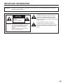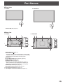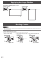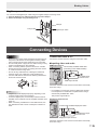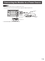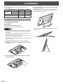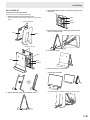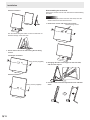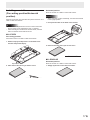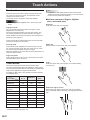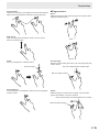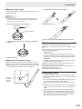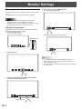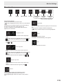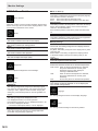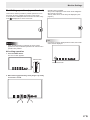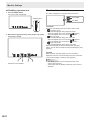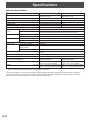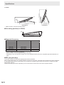
1
LL-S242A-W LL-P202V LCD MONITOR OPERATION MANUAL IMPORTANT: To aid reporting in case of loss or theft, please record the product’s model and serial numbers in the space provided. The numbers are located in the rear of the product. Model No.: Serial No.: U.S.A. ONLY This device complies with Part 15 of the FCC Rules. Operation is subject to the following two conditions: (1) This device may not cause harmful interference, and (2) this device must accept any interference received, including interference that may cause undesired operation. WARNING: FCC Regulations state that any unauthorized changes or modifications to this equipment not expressly approved by the manufacturer could void the user’s authority to operate this equipment. NOTE: This equipment has been tested and found to comply with the limits for a Class B digital device pursuant to Part 15 of the FCC Rules. These limits are designed to provide reasonable protection against harmful interference in a residential installation. This equipment generates, uses and can radiate radio frequency energy and, if not installed and used in accordance with the instructions, may cause harmful interference to radio communications. However, there is no guarantee that interference will not occur in a particular installation. If this equipment does cause harmful interference to radio or television reception, which can be determined by turning the equipment off and on, the user is encouraged to try to correct the interference by one or more of the following measures: - Reorient or relocate the receiving antenna. - Increase the distance between the equipment and receiver. - Connect the equipment into an outlet on a circuit different from that to which the receiver is connected. - Consult the dealer or an experienced radio/TV technician for help. Use nothing but the included cables and AC cord to insure compliance with FCC regulation for Class B computing equipment. U.S.A. ONLY CAN ICES-3(B)/NMB-3(B) CANADA ONLY IMPORTANT INFORMATION WARNING: TO REDUCE THE RISK OF FIRE OR ELECTRIC SHOCK, DO NOT EXPOSE THIS PRODUCT TO RAIN OR MOISTURE. CAUTION RISK OF ELECTRIC SHOCK DO NOT OPEN CAUTION: TO REDUCE THE RISK OF ELECTRIC SHOCK, DO NOT REMOVE COVER. NO USER-SERVICEABLE PARTS INSIDE. REFER SERVICING TO QUALIFIED SERVICE PERSONNEL. The lightning flash with arrowhead symbol, within a triangle, is intended to alert the user to the presence of uninsulated “dangerous voltage” within the product’s enclosure that may be of sufficient magnitude to constitute a risk of electric shock to persons. The exclamation point within a triangle is intended to alert the user to the presence of important operating and maintenance (servicing) instructions in the literature accompanying the product. 3 E DEAR SHARP CUSTOMER Thank you for your purchase of a SHARP LCD product. To ensure safety and many years of trouble-free operation of your product, please read the Safety Precautions carefully before using this product. SAFETY PRECAUTIONS Electricity is used to perform many useful functions, but it can also cause personal injuries and property damage if improperly handled. This product has been engineered and manufactured with the highest priority on safety. However, improper use can result in electric shock and/or fire. In order to prevent potential danger, please observe the following instructions when installing, operating and cleaning the product. To ensure your safety and prolong the service life of your LCD product, please read the following precautions carefully before using the product. 1. Read instructions — All operating instructions must be read and understood before the product is operated. 2.Keep this manual in a safe place — These safety and operating instructions must be kept in a safe place for future reference. 3. Observe warnings — All warnings on the product and in the instructions must be observed closely. 4. Follow instructions — All operating instructions must be followed. 5.Cleaning — Unplug the power cord from the AC outlet before cleaning the product. Use a dry cloth to clean the product. Do not use liquid cleaners or aerosol cleaners. 6.Attachments — Do not use attachments not recommended by the manufacturer. Use of inadequate attachments can result in accidents. 7.Water and moisture — Do not use the product near water. Do not install the product in a place where water may splash onto it. Be careful of equipment which drains water such as an air-conditioner. 8. Ventilation — The vents and other openings in the cabinet are designed for ventilation. Do not cover or block these vents and openings since insufficient ventilation can cause overheating and/or shorten the life of the product. Do not place the product on a sofa, rug or other similar surface, since they can block ventilation openings. Do not place the product in an enclosed place such as a bookcase or rack, unless proper ventilation is provided or the manufacturer’s instructions are followed. 9.Power cord protection — The power cords must be routed properly to prevent people from stepping on them or objects from resting on them. 10.The screen used in this product is made of glass. Therefore, it can break when the product is dropped or applied with impact. Be careful not to be injured by broken glass pieces in case the screen breaks. 11. Overloading — Do not overload AC outlets or extension cords. Overloading can cause fire or electric shock. 12.Entering of objects and liquids — Never insert an object into the product through vents or openings. High voltage flows in the product, and inserting an object can cause electric shock and/or short internal parts. For the same reason, do not spill water or liquid on the product. 13.Servicing — Do not attempt to service the product yourself. Removing covers can expose you to high voltage and other dangerous conditions. Request a qualified service person to perform servicing. 14.Repair — If any of the following conditions occurs, unplug the power cord from the AC outlet, and request a qualified service person to perform repairs. a. When the power cord or plug is damaged. b. When a liquid was spilled on the product or when objects have fallen into the product. c. When the product has been exposed to rain or water. d. When the product does not operate properly as described in the operating instructions. Do not touch the controls other than those described in the operating instructions. Improper adjustment of controls not described in the instructions can cause damage, which often requires extensive adjustment work by a qualified technician. e. When the product has been dropped or damaged. f.When the product displays an abnormal condition. Any noticeable abnormality in the product indicates that the product needs servicing. 15.Replacement parts — In case the product needs replacement parts, make sure that the service person uses replacement parts specified by the manufacturer, or those with the same characteristics and performance as the original parts. Use of unauthorized parts can result in fire, electric shock and/or other danger. 16.Safety checks — Upon completion of service or repair work, request the service technician to perform safety checks to ensure that the product is in proper operating condition. 17.Wall mounting — When mounting the product on a wall, be sure to install the product according to the method recommended by the manufacturer. 18.Heat sources — Keep the product away from heat sources such as radiators, heaters, stoves and other heat-generating products (including amplifiers). E 4 SAFETY PRECAUTIONS (Continued) 19.Usage of the monitor must not be accompanied by fatal risks or dangers that, could lead directly to death, personal injury, severe physical damage or other loss, including nuclear reaction control in nuclear facility, medical life support system, and missile launch control in a weapon system. 20.Do not touch the parts of the product or the AC adapter that become hot for long periods of time. Doing so may result in low-temperature burns. To maintain compliance with EMC regulations, use shielded cables to connect to the following terminals: HDMI input terminal and DisplayPort input terminal. If a monitor is not positioned in a sufficiently stable location, it can be potentially hazardous due to falling. Many injuries, particularly to children, can be avoided by taking simple precautions such as: •Using fixing devices like wall mount brackets recommended by the manufacturer. •Only using furniture that can safely support the monitor. •Ensuring the monitor is not overhanging the edge of the supporting furniture. •Not placing the monitor on tall furniture (for example, cupboards or bookcases) without anchoring both the furniture and the monitor to a suitable support. •Not standing the monitors on cloth or other materials placed between the monitor and supporting furniture. •Educating children about the dangers of climbing on furniture to reach the monitor or its controls. 5 E TIPS AND SAFETY INSTRUCTIONS - The TFT color LCD panel used in this monitor is made with the application of high precision technology. However, there may be minute points on the screen where pixels never light or are permanently lit. Also, if the screen is viewed from an acute angle there may be uneven colors or brightness. Please note that these are not malfunctions but common phenomena of LCDs and will not affect the performance of the monitor. - Do not display a still picture for a long period, as this could cause a residual image. - Never rub or tap the monitor with hard objects. - Please understand that SHARP CORPORATION bears no responsibility for errors made during use by the customer or a third party, nor for any other malfunctions or damage to this product arising during use, except where indemnity liability is recognized under law. - This monitor and its accessories may be upgraded without advance notice. - Do not use the monitor where there is poor ventilation, where there is a lot of dust, where humidity is high, or where the monitor may come into contact with oil or steam. - Ensure that the monitor does not come into contact with water or other fluids. Ensure that no objects such as paper clips or pins enter the monitor as this could lead to fire or electric shock. - Do not place the monitor on top of unstable objects or in unsafe places. Do not allow the monitor to receive strong shocks or to strongly vibrate. Causing the monitor to fall or topple over may damage it. - Continuous Operation Time and Warranty This product has been designed based on the assumption of 15 or fewer hours of usage in one day. Continuous usage that exceeds 15 hours in one day is not covered by the warranty. - Do not use the monitor near heating equipment or in places where there is likelihood of high temperature, as this may lead to generation of excessive heat and outbreak of fire. - Do not use the monitor in places where it may be exposed to direct sunlight. - The AC outlet shall be installed near the equipment and shall be easily accessible. - Do not touch the screen when starting the LCD monitor. If the screen is touched, the monitor may not function correctly. In this situation, turn the LCD monitor off, wait at least 5 seconds, and then turn on the monitor again. - Do not use in applications where water or other fluid may adhere to the screen. If fluid adheres to the screen, the touch panel may not operate correctly. - Do not use your nails, touch pens or digitizer pens other than the one supplied, sharp pencils, or other hard objects to operate the unit. - If the pen tip of the digitizer pen is worn or damaged, replace the pen tip. Failure to do so may scratch the screen or cause the digitizer pen functions to not operate correctly. - Depending on the application you are using, the supplied touch pen and digitizer pen may not function. - If another USB device is connected to the computer to which the touch panel is connected, do not operate the USB device during touch panel input. Input may not take place correctly. - Do not use liquid such as alcohol in cleaning the screen. - Keep all cables off the touch panel. Not doing so may lead to LCD monitor malfunctions. - If used in a room (or location) with drastic temperature differences, the display quality of the screen and the quality of touch panel performance may decrease. E 6 The Power Cord and AC Adapter - Use only the power cord and AC adapter supplied with the monitor. - When handling the AC adapter, observe the following: Incorrect handling may result in fire, electric shock, or injury. • Do not drop the AC adapter or subject it to impact. • Never disassemble the AC adapter. It contains high voltage parts that are dangerous to touch. • The AC adapter is for indoor use only. Do not use it outside. • Do not use the supplied AC adapter with other devices. - Do not damage the power cord and AC adapter nor place heavy objects on it, stretch it or over bend it. Also, do not add extension cords. Damage to the cord may result in fire or electric shock. - Do not use the power cord with a power tap. Adding an extension cord may lead to fire as a result of overheating. - Do not remove or insert the power plug with wet hands. Doing so could result in electric shock. - Unplug the power cord if it is not used for a long time. - Do not attempt to repair the power cord if it is broken or malfunctioning. Refer the servicing to the service representative. - Do not stay in contact with the parts of the product and the AC adapter that become hot for long periods of time. Doing so may result in low-temperature burns. - For your health, observe the following: • If using the monitor continuously, take a 10- to 15-minute break every hour to rest your eyes. • Do not use the monitor in high-contrast light conditions. • Do not use the monitor in locations where the screen is subject to direct sunlight. Manual Scope - This document is the operation manual for both the LL‑S242A-W and the LL-P202V. - Illustrations of the LL-P202V are used in this document as an example. - Microsoft, Windows and Windows Vista are registered trademarks of Microsoft Corporation. - The terms HDMI and HDMI High-Definition Multimedia Interface, and the HDMI Logo are trademarks or registered trademarks of HDMI Licensing LLC in the United States and other countries. - DisplayPort is a registered trademark of Video Electronics Standards Association. - Adobe, Acrobat, and Reader are either registered trademarks or trademarks of Adobe Systems Incorporated in the United States and/or other countries. - MHL, the MHL logo, and Mobile High-Definition Link are trademarks or registered trademarks of MHL, LLC in the United States and other countries. - All other brand and product names are trademarks or registered trademarks of their respective holders. - Language of OSD menu used in this manual is English by way of example. - Illustrations in this manual may not exactly represent the actual product or display. LED Backlight ● The LED backlight in this product has a limited lifetime. * If the screen gets dark or does not turn on, it may be necessary to replace the LED backlight. This LED backlight is exclusive to this product and must be replaced by an authorized Sharp servicing dealer or service center. * Please contact your local Sharp servicing dealer or service center for assistance. Contents IMPORTANT INFORMATION.............................................3 DEAR SHARP CUSTOMER...............................................4 SAFETY PRECAUTIONS...................................................4 TIPS AND SAFETY INSTRUCTIONS................................6 Supplied Components......................................................7 System Requirements......................................................8 Part Names........................................................................9 Applying the Logo Sticker.............................................10 Binding Cables................................................................10 Video cable and USB cable........................................10 Digitizer pen cable....................................................... 11 Connecting Devices....................................................... 11 Connection with a PC.................................................. 11 Connecting USB devices............................................12 Connecting the digitizer pen (LL-P202V)....................12 Connecting the Monitor to a Power Source.................13 Installation.......................................................................14 Installing on a stand (Standing position).....................14 Installing on a table (Pen writing position/Horizontal position)....................17 Turning Power On/Off.....................................................18 Turning on the power..................................................18 Turning off the power..................................................18 Installing the Software...................................................19 Installation...................................................................19 Touch Actions.................................................................20 Touch action modes....................................................20 Touch action................................................................20 Digitizer pen................................................................22 Other functions............................................................23 Cautionary points........................................................23 Monitor Settings.............................................................24 Menu operations.........................................................24 Menu functions............................................................25 SETUP Menu Details..................................................26 Prohibiting operations (operation lock)........................27 Monitor status indicators.............................................28 Troubleshooting..............................................................29 Specifications ................................................................30 For information on the Pen Software, see the Pen Software Operation Manual. Supplied Components If any component should be missing, please contact your dealer. Component LL-S242A-W LL-P202V Liquid Crystal Display Monitor 1 AC adapter 1 Power cord 1 Digitizer pen - 1 Digitizer pen stand - 1 Digitizer pen cable clamper (clamper, fixing screw: 1) - 1 Digitizer pen spare pen tips - 1 Touch pen 1 - Variable stand (stand, fixing screws: 4, hexagonal wrench) - 1 Rack stand (front, back, support, fixing screws: 2) 1 - USB cable (USB-microUSB Type B) 1 CD-ROM (Utility Disc) 1 Setup Manual 1 Logo sticker 1 * SHARP Corporation holds authorship rights to the Utility Disk program. Do not reproduce it without permission. * Keep packaging for use when transporting monitor, etc. 7 E System Requirements nTouch panel To use the touch panel, the monitor must be connected to a computer using a USB cable. Touch panel operating conditions are as described below. Computer PC/AT compatible computer with a USB 1.1 port and able to output a resolution of 1920 x 1080. Windows 8.1 (32-bit or 64-bit version), Windows 8 (32-bit or 64-bit version), OS Windows 7 (32-bit or 64-bit version), Windows Vista (32-bit or 64-bit version) • Windows 7 or later is recommended for touch action. • The digitizer pen can be used with Windows 7 or later. • On Windows 7 or later, the touch panel operates with the standard Windows driver. On Windows Vista, the touch panel driver must be installed on the computer from the supplied CD-ROM. (See page 19) E 8 Part Names nFront view LL-S242A-W LL-P202V 1 1. Power LED (See page 18.) 1 nRear view LL-P202V 3 2 LL-S242A-W 1 3 3 2 1 3 6 6 7 7 8 8 9 4 10 11 9 4 10 11 5 5 1. VESA holes (See page 31.) 2. Anti-theft hole ( ) Allows the monitor to be secured using a commercially available anti-theft lock. The anti-theft hole is compatible with Kensington’s MicroSaver security system. 3. Speakers 4. Power/Menu button (See page 18, page 24.) 5. Cable clamp (See page 10.) 6. USB terminal (See page 12.) 7. Digitizer pen connection terminal (See page 12.) The LL-S242A-W is not supplied with a digitizer pen. Purchase a commercially available pen, as required. 8. HDMI input terminal (See page 11.) 9. DisplayPort input terminal (See page 11.) 10. Touch panel terminal (See page 12.) 11. AC adapter connection terminal (See page 13.) 9 E Applying the Logo Sticker You can apply the supplied logo sticker to the unit. Attach as shown in the following diagram, as required. Landscape orientation Portrait orientation Power LED Power LED Binding Cables Caution • When connecting cables, spread a soft cloth on a stable level surface such as a desk, and gently place the monitor on it with the screen facing down. Video cable and USB cable Secure the video cable (HDMI or DisplayPort) and USB cable using the cable clamp. 1. Remove the cable clamp. 2. Route the cables through the cable 3. Push the cable clamp down into place. restraint slot. Cable restraint slot Cable clamp E 10 Cable clamp Binding Cables Digitizer pen cable You can secure the digitizer pen cable using the supplied clamper and fixing screw. 1. Pass the digitizer pen cable through the ring of the clamper. 2. Attach the clamper using the fixing screw. Clamper Fixing screw Digitizer pen cable Connecting Devices Caution • Be sure to turn off the power and disconnect the plug from the power outlet before connecting/disconnecting cables. Also, read the manual of the equipment to be connected. • Do not forcibly bend or apply force to cables. Doing so may result in wire breakage or other damage. • When connecting cables, spread a soft cloth on a stable level surface such as a desk, and gently place the monitor on it with the screen facing down. • Do not use any cable that has a damaged or deformed terminal. Using such cables may cause malfunctions. • Connect USB devices that have the following thicknesses around the connector area. B D A A B C D 12mm 38mm 8mm 17mm C TIPS • Images may not be displayed properly depending on the computer (video card) to be connected. • To use the digitizer pen, the necessary software must be installed on the computer from the supplied CD-ROM. (See page 19.) • When connecting a USB device to the USB terminal, use only USB devices with current consumption of 500mA or lower. Connection with a PC Connect the monitor and a PC using the connection cable. nInputting video and audio HDMI input terminal Commercially available HDMI cable (conforming to the HDMI standard) To HDMI output terminal on PC HDMI input terminal Check the orientation of the connector and insert it horizontally as far as it will go. • It is possible to connect the monitor’s HDMI input terminal to a smartphone or similar MHL-compliant device using a commercially available MHL cable. This product supports MHL 1. DisplayPort input terminal Commercially available DisplayPort cable To DisplayPort output terminal on PC DisplayPort input terminal Check the orientation of the connector and insert it horizontally as far as it will go. 11 E Connecting Devices TIPS • The length of the signal cables or surrounding environment may affect the image quality. • The video from the terminal that has signal input is displayed. In this state, even if a signal is input from the other terminal, the display is not switched. To switch the display, use [Input Select] on the menu screen. (See page 25.) • If the LCD monitor is turned on when there are input signals from both terminals, the video from the DisplayPort input terminal is displayed (factory default). Connecting the digitizer pen (LL-P202V) When using the supplied digitizer pen, connect the digitizer pen cable. Digitizer pen cable nUsing the touch panel To use the touch panel, connect the monitor to a USB port on a PC using the supplied USB cable. Digitizer pen connection terminal Check the orientation of the connector and insert it horizontally as far as it will go. Supplied USB cable USB terminal To USB port on PC Touch panel terminal Check the orientation of the connector and insert it horizontally as far as it will go. Connecting USB devices When using a commercially available mouse, keyboard, or other device, connect the device to the USB port. USB cable USB terminal Check the orientation of the connector and insert it horizontally as far as it will go. E 12 Connecting the Monitor to a Power Source Caution • Use only the AC adapter and power cord supplied with the monitor. 1. Connect the monitor to the power outlet using the supplied AC adapter and power cord. Back of monitor For power outlet AC adapter connection terminal Core restrainer AC adapter (Supplied) Power cord (Supplied) AC adapter core 2. Push the AC adapter core into the core restrainer. 13 E Installation You can install the touch display for each monitor in the following positions. Installation position LL-S242A-W LL-P202V Rack stand Yes No Variable stand No Yes Pen writing position No Yes Horizontal position Yes Yes Standing position 3. Place the monitor in the standing position, and adjust the angle of the stand. Hold the display with one hand so that it does not fall over, hold the rear leg of the stand with your other hand, and adjust the angle of the stand. Installing on a stand (Standing position) nLL-P202V Placement on the variable stand Place the unit on the supplied variable stand. Caution • The variable stand is designed for placement of the unit in the landscape orientation. It cannot be used for the portrait orientation. • For installation, place the monitor face-down carefully on a soft cloth on top of a flat, stable surface. • Applying excessive pressure to the LCD panel with your hands may result in damage to the unit. • Be careful not to get your fingers caught when adjusting the angle, for example. The legs can extend about 20 to 75 degrees in relation to the flat surface. 20° 1. Place the variable stand on the rear of the monitor, insert the fixing screws and tighten by hand to position the stand. 75° 2. Securely tighten the fixing screws using the supplied hexagonal wrench. E 14 Installation 3. Peel off the adhesive tape securing the support to the back side. nLL-S242A-W Placement on the rack stand Place the unit on the supplied rack stand. 1. Attach the back of the stand to the front. Place the front and back sides together, and attach the hinge. Tape Back Front hinge part Front Support Back 4. Fold down the support, inserting the tabs into the holes on the front side. Back hinge part 5. Position the stand. Tape Front Back Support 6. Place the monitor in the stand. Landscape orientation 2. Spread the base of the front and back sides. Run the cables out between the legs of the back side. 15 E Installation Disassembling the rack stand Portrait orientation Remove the monitor from the rack stand before disassembling the stand. Caution • After removing the monitor from the rack stand, store the stand so that the screws will not be lost. 1. Remove the screws and remove the monitor. Remove fixing screws Run the cables along the hollow on the front side and out between the legs of the back side. 7. Secure the monitor to the stand using the two fixing screws. Landscape orientation Fixing screws (supplied) 2. Disengage the tabs of the support on the front side, and raise the support. Portrait orientation Fixing screws (supplied) E 16 3. Fold the stand closed and separate the front and back sides. Installing on a table (Pen writing position/Horizontal position) Remove the monitor from the stand and place face-down on a table or other level surface. Horizontal position Place the monitor on a table or other level surface. Caution • When using the monitor horizontally, use the horizontal tab in the upright position. 1. Lift up the two tabs on the back of the monitor. Caution • Do not exert a large amount of force on the monitor from above. Doing so may damage the flap. (LL-P202V) • After removing the monitor from the rack stand, store the stand so that the screws will not be lost. nLL-P202V Pen writing position Place the monitor on a table or other level surface. 1. Hold the flap by the depression on the back of the monitor and pull the flap up. 2. Place the monitor where you want to use it. nLL-S242A-W Depression 2. Place the monitor where you want to use it. Horizontal position Place the monitor on a table or other level surface. 1. Simply lay the unit on the desired location. 17 E Turning Power On/Off Turning on the power Turning off the power 1. Press the POWER button. 1. Turn off the PC. 2. Depress the POWER button for around 2 seconds. POWER button POWER button Press Power LED The power LED turns on. Caution Status of the monitor Green lit Signal input Orange lit No signal input Alternately flashing red and Abnormal temperature green Caution • When switching the POWER button off and back on, always wait for an interval of at least 5 seconds. Rapid switching may lead to errors or malfunctions. • For a complete electrical disconnection, pull out the main plug. E 18 The power LED turns off. • If the monitor will not be used for a long time, disconnect the power plug from the power outlet. 2. Turn on the PC. The screen appears. Status Depress for around 2 seconds Installing the Software To use the touch panel or the supplied digitizer pen, the required software must be installed for the operating system of the connected computer. The required software is given below. LL-S242A-W LL-P202V Windows 8.1 / 8 Windows 7 Windows Vista Windows 8.1 / 8 Windows 7 Windows Vista Digitizer pen utility No No No Yes Yes No Touch panel driver for Windows Vista No No Yes No No Yes Installation Install the software from the suppolied CD-ROM. For details, refer to the “Digitizer Pen Utility Operation Manual” and “Touch Panel Driver Operation Manual for Windows Vista” in the Manual folder on the supplied CD-ROM. 19 E Touch Actions Touch action modes TIPS There are three touch action modes: finger/pen mode, penonly mode, and finger-only mode. These modes can be changed on the menu screen. The monitor is set to finger/pen mode when shipped. Caution • Use the supplied pen (digitizer pen or touch pen) in pen mode. • In Windows 7, if the checkmark has been removed from “Enable multi-touch gestures and inking” in “Pen and touch” in Control Panel, select the checkbox. nActions common to fingers, digitizer pens, and touch pens Single-tap Touch the screen with your finger/pen. Finger/pen mode You can perform touch actions with your fingers or pens (digitizer pen and touch pen). Touch actions performed with a pen are given priority, and any actions performed at the same time with your fingers will be disabled. Pen actions have priority, even during hover operations. (See page 22.) Finger actions will be enabled again about 0.5 seconds after you remove the pen from the screen. Pen-only mode This mode is for pen (digitizer pen and touch pen) use only. You cannot touch the screen with your finger. You can touch the menu screen (See page 24) with your finger. When the digitizer pen is connected, the touch panel does not respond to the touch pen. Double-tap Quickly touch the screen twice with your finger/pen. Finger-only mode This mode is for finger use only. You cannot touch the screen with the digitizer pen or touch pen. Touch action Touch actions that can be used with this monitor differ according to operating system and application. The functions of touch actions are also different. For details, check Windows Help and the application’s support documentation. For details on Mac, refer to the operation manual for the Mac touch display driver. Touch action Windows 8.1 / 8 Windows 7 Windows Vista* Single-tap Yes Yes Yes Double-tap Yes Yes Yes Swipe Yes Yes Yes Swipe from edge of screen Yes No No Drag-and-drop Yes Yes Yes Slide to pan Yes Yes No Flicks Yes Yes No Press-and-hold Yes Yes Yes Zoom Yes Yes No Press-and-tap No Yes No Rotate Yes Yes No OS * You must install the touch panel driver to your PC from the included CD-ROM. (See page 19.) E 20 Swipe Touch the screen with your finger/pen, move without lifting, and then stop. Swipe from edge of screen After touching the edge of the screen with your finger/pen, move horizontally without releasing your finger/pen and then stop. Touch Action Drag-and-drop Touch the screen with your finger/pen and move without lifting. When you have finished the movement, lift your finger/pen. nFinger actions Zoom While touching the screen with two fingers, move them closer together and farther apart. Slide to pan With your finger/pen touching the screen, move it up and down to scroll the screen. Flicks Move your finger/pen in a flicking motion. Flick your finger Pinch Stretch Press-and-tap With one finger touching the screen, tap once (single tap) with another finger. Tap once (single tap) with another finger With one finger touching Press-and-hold Press briefly with your finger/pen, and then lift your finger/pen from the screen. Rotate While touching the monitor with one finger, move the other finger in the direction you wish to rotate in. Move another finger in the desired direction of rotation With one finger touching 21 E Touch Action Digitizer pen The LL-P202V monitor supports a digitizer pen. To use the digitizer pen, the utility software must be installed. (See page 19.) nDigitizer pen actions Button operations Function button 2 Pen tip TIPS • The shortcut launcher is not displayed on the Windows 8.1/8 Start screen or on the Windows Store screen. • When the digitizer pen is connected, digitizer pen actions are enabled and touch pen actions are disabled. To use touch pen actions, disconnect the digitizer pen. • The digitizer pen supports pen pressure functions. The pen can be used with software that responds to pen pressure. • If the digitizer pen does not operate correctly, try placing the tip of the pen vertically on the screen. nDigitizer pen stand Place the digitizer pen in the pen stand when it is not being used. Function button 1 Function button 1: Pressing and holding this button and touching the screen performs the same action as a right-click on a mouse. (factory default) Function button 2: Pressing and holding this button while moving the pen on the screen enables the eraser function. (factory default) Digitizer pen Pen stand You can change the functions that are assigned to the function buttons using the digitizer pen utility. Hover operations The unit will recognize when the tip of the pen is hovering within 15 mm of the screen, allowing you to position the pointer without touching the screen. Shortcut launcher When you press function button 1 while in the hovering state, a circular shortcut launcher menu will appear. You can select the desired operation from the menu. The shortcut launcher disappears when you select a function or press function button 1 again. You can wrap the digitizer pen cable around the digitizer pen stand. Top cover Pen tip storage cap Bottom cover Close the top cover and bottom cover as shown in the following diagram. You can press [Launch registered app] to register an application and its name. Once registered, [Launch registered app] is changed to the name of the registered application, allowing the application to be launched from the shortcut launcher. E 22 Touch Action nSpare pen tip storage 1. Unscrew the pen tip cover and remove it. The pen stand features a pen tip storage area where you can store spare pen tips. TIPS • Spare pen tips are not stored in the stand at the time of purchase. Store the spare pen tips in the pen stand to make sure you do not lose them. 1. Remove the spare pen tip storage cap. 2. Pull out the pen tip. Cap Pen tip storage 2. Insert the spare pen tips into the holes in the pen tip storage. 3. Insert a new pen tip, and reattach the pen tip cover. Other functions In Windows 8.1/8, input panel functions can be used. In Windows 7, touch pointer and input panel functions can be used. For information about the touch pointer and input panel functions, see Windows Help. 3. Reattach the cap. nReplacing the digitizer pen tip Replace the pen tip when it is worn or damaged. Using the digitizer pen with a worn or damaged pen tip may scratch the surface of the monitor, or may cause the digitizer pen function to stop operating. Pen tips will wear with normal use. Touch pointer : A translucent image of a mouse appears near the point touched. The left/right buttons of the image can be clicked to perform the same actions as left/right clicking a mouse. Input panel : A software keyboard and an input panel with handwriting recognition appear on the screen. Windows 8.1/8 and Windows 7 (excluding Starter), the ink function of Microsoft Office can be used. Handwritten comments can be written, and handwriting can be recognized using this function. For details, see Microsoft Office Help. Cautionary points Replace when worn down to this level. • When performing touch actions, use the ball of your finger. • Use only the supplied digitizer pen or touch pen to perform pen actions. • Do not use the supplied pen (digitizer pen or touch pen) for any purpose other than touch panel operation. • Do not press hard on the tip of the digitizer pen or touch pen. • If there is dirt or foreign matter on the tip of the digitizer pen or touch pen, remove it. Failure to do so may damage the screen. • Even when in pen-only mode, the unit may respond to objects other than the supplied digitizer pen or touch pen. • When performing pen actions with the supplied digitizer pen or touch pen, do not touch the screen with anything other than the hand that is holding the pen. 23 E Monitor Settings Menu operations The monitor settings are configured by displaying the menu screen. The operations on this page are the basic operations. 4. Touch [Exit] or press the MENU button. The menu screen disappears. Caution • Do not turn off the power while the menu screen is displayed. Doing so may initialize the settings. • While the menu screen is displayed, touch actions are not possible other than those for the menu screen. nExample of operation Exit Operations on the menu screen are described here using adjusting the volume as an example. 1. Press the MENU button. The menu screen appears. Return Mute Touch [Return] to return to the level above. MENU button Press Exit Return Mute 2. Touch [Volume]. TIPS • If no actions are made on the adjustment bar display screen for around 10 seconds, the screen returns to the ordinary display screen. • The menu screen can also be operated using your finger in pen-only mode. 3. Touch the adjustment bar and slide your finger to either side to adjust the volume. Exit 30 Return Adjustment bar E 24 Mute Monitor Settings Menu functions Exit Setup Input Select Volume Finger-only Pen-only mode mode Finger/pen mode Touch mode selection Touch mode selection These icons switch the touch action mode. A ( ) mark is displayed at the top of the icon for the selected mode. The mode can be checked using the touch mark located on the right-side of the screen. (See pages 26, 28) On the LL-P202V, the icon pen design varies when the digitizer pen is connected. Finger/pen mode This icon switches the touch action mode to finger/pen mode. When using the touch pen (digitizer pen is not connected), appears. When the digitizer pen is connected, appears. The touch mark (see page 28) becomes the finger/pen mark or . Input Select This icon manually switches the signal input source from the PC. Touching the icon displays HDMI and DisplayPort. A ( ) mark is added to the input source being displayed. Setup This icon configures the monitor. For details on individual settings, see page 26. Exit This icon closes the menu screen. Pen-only mode This icon switches the touch action mode to pen-only mode. When using the touch pen (digitizer pen is not connected), appears. When the digitizer pen is connected, appears. The touch mark becomes the finger/pen mark or . Finger-only mode This icon switches the touch action mode to finger-only mode. . The touch mark becomes the finger-only mark Volume This icon adjusts speaker and headphone volume. Touching [Mute] temporarily sets the volume to 0. Touching [Mute] again returns the volume to the previous level. 25 E Monitor Settings SETUP Menu Details Menu Position Position When the monitor is used in portrait orientation (power/menu button on the top), this icon moves the display position of the menu screen to the bottom of the screen. Mode Mode Normal This mode is suited to normal PC screen display. Pen Writing This mode is suited to pen writing position. Game This mode is suited to video games. Multimedia This mode is suited to video playback. User The user can adjust the image quality. Brightness Brightness This icon adjusts the brightness of the backlight. Other Other Video input RGB Range This setting configures the range of the RGB input signal. Use “Auto” for normal operation. If the range cannot be set correctly in “Auto”, adjust to match the video. Varying the setting may cause floating blacks or reduced gradations to appear. DisplayPort Mode This setting configures the DisplayPort mode. Use “DisplayPort Mode1” for normal operation. If the following symptoms occur in “DisplayPort Mode1”, set the mode to “DisplayPort Mode2”. • The video is interrupted, flickers, or is not displayed. Signage Set to “ON” if using the monitor in a signage application (controlled using e-Signage (optional)). E 26 Mode on Start Up Touch Mode This setting configures the touch action mode (See page 25) used when the monitor is turned on. Reset: The monitor starts in finger/pen mode. Save: The monitor starts in the mode that was last used. Menu Position This setting is used to set the position of the menu at startup. Reset: Sets the display position of the menu at startup to “Bottom in Portrait Orientation”. Save: Sets the position to that when power was last turned off. Pen Position Adjustment This setting adjusts the pointer position if the pen tip position is different than the pointer indicator position. Display Settings Mark Indicators Touch mark: This setting configures how to display the touch mark (See page 28). Key Mark: This setting configures how to display the key mark (See page 28). Mark Position: This setting configures the display position of the status display mark (touch mark/key mark) on the screen. LED Status This mark toggles the power LED on/off. TEMPERATURE ALERT Selects the notification method for an abnormal temperature. OSD & LED:When an abnormal temperature is detected, the power LED flashes in red and green alternately and the screen displays a message: TEMPERATURE. LED:When an abnormal temperature is detected, the power LED flashes in red and green alternately. OFF: Do not notify about an abnormal temperature. Logo Screen This setting configures whether or not to display the logo screen during startup. Language Language This setting changes the menu screen display language. Reset Reset This setting resets all settings to their factory default. Monitor Settings Prohibiting operations (operation lock) This function makes it possible to prohibit operations to turn the power off and to prohibit touch action on the screen. If an operation is attempted when the monitor is locked, a key mark is displayed for around 5 seconds. Operation lock is enabled. A key mark is displayed on the screen and it disappears after around 5 seconds. The key mark can be set to always be displayed. (See page 26.) TIPS Caution • When the MENU button is pressed, the menu screen appears and only the disable operation lock and exit menu operation are possible. • If the menu screen is displayed when locked, the invalid action mark is displayed. Locking operation 1. Press the MENU button. The menu screen appears. MENU button Invalid action mark Press 2. While touching [Input Select], touch [Finger-only mode] for at least 1 second. 27 E Monitor Settings Monitor status indicators n Disabling operation lock 1. Press the MENU button. The menu screen is displayed. The status is displayed on the right-side of the screen. Touch Mark MENU button Press 2. While touching [Input Select], touch [Finger-only mode] for at least 1 second. Key Mark Touch Mark The touch mark displays the current touch action mode. Finger/pen mode This mark is displayed during finger/pen mode. appears. When the digitizer pen is not connected, When the digitizer pen is connected, appears. Pen-only mode This mark is displayed during pen-only mode. When the digitizer pen is not connected, appears. When the digitizer pen is connected, appears. Finger-only mode This mark is displayed during finger-only mode. Marks are displayed for about 5 seconds after changing setting. You can also set marks to always be displayed. (See page 26.) Key Mark When operation lock (See page 27) is set, the mark is displayed for around 5 seconds when the screen is touched. It can be set to display constantly. (See page 26.) TIPS Operation lock is disabled. E 28 • The display position can be changed from the menu screen. (See page 26.) • These marks are not displayed while the menu screen is displayed. Troubleshooting If you are experiencing any problem with your display, before calling for service, please review the following troubleshooting tips. There is no picture or sound. • Are the AC adapter and power cord connected correctly? (See page 13.) • Is the power on? (See page 18.) There is a picture but no sound. • Make sure the volume is not set to minimum. (See page 25.) • Is the sound muted? (See page 25.) • No sound will come from the speakers when the monitor is in standby mode (when the power LED is orange). (See page 18.) The response of the touch screen is slow. Some parts of the screen do not respond. • When starting your computer or connecting the USB cable, do not touch the touch panel. • When starting the LCD monitor, do not touch the screen. If the screen is touched, the monitor may not function correctly. In this situation, turn off the LCD monitor power, wait 5 seconds or longer, and then turn the power on again. • While the menu screen is displayed, touch actions are not possible other than those for the menu screen. First exit the menu screen and then perform the operation. • There may be no response if the supplied digitizer pen / touch pen and your hand that is on the screen are too close. In such cases, perform the operation with the pen and your hand spaced farther apart. The video does not appear. • Is the cable certified for HDMI or DisplayPort? The monitor will not work unless a standards-compliant cable is used. • Is the input signal compatible with this monitor? (See page 33.) • Is the monitor connected correctly to the PC? • Is the PC turned on? • Is video being output from the PC? • Is the PC in power-saving mode? Try pressing a key on the keyboard or moving the mouse. • Turn off the LCD monitor power, wait 5 seconds or longer, and then turn the power on again. The video does not appear properly. • If a powerful amount of strain is exerted on the touch display, a portion of the display may remain on the screen. In this situation, turn off the monitor power, wait 5 seconds or longer, and then turn the power on again. The touch panel does not respond. • Is the USB cable connected properly? (See page 12.) • The touch panel may not work properly if there is a large contact area (e.g. if the screen is touched with the palm of the hand). • Is the monitor in pen-only mode? Touch action is disabled in pen-only mode. (See page 20, 25.) • Is the monitor in finger-only mode? Digitizer pen and touch pen actions are disabled in finger-only mode. (See page 20, 25.) • Are monitor operations locked? (See page 27.) • When there is no signal input to the LCD monitor, actions on the touch panel are not possible. Please operate the PC using the mouse and keyboard. • Is the digitizer pen cable connected properly? (See page 12.) • Is the tip of the digitizer pen worn? If it is worn, replace the pen tip. (See page 23.) • When the digitizer pen is connected, digitizer pen actions are enabled and touch pen actions are disabled. To use touch pen actions, disconnect the digitizer pen. • If you want to position the monitor further away than the supplied USB cable will allow, extend the cable using a USB cable with a repeater. 29 E Specifications nProduct Specifications Model LCD component LL-S242A-W (white) LL-P202V 24” Class [23-5/8” (60.0 cm) 20” Class [19-1/2” (49.5 cm) diagonal] TFT LCD diagonal] TFT LCD Max. resolution (pixels) 1920 x 1080 Max. colors Approx. 16.70 million colors Approx. 16.77 million colors Pixel pitch 0.272 mm (H) x 0.272 mm (V) 0.225mm (H) x 0.225 mm (V) Viewing angle 178° right/left/up/down (contrast ratio ≥ 10) Screen active area inch (mm) 20-1/2 x 11-9/16 (521.3 x 293.2) 17 x 9-9/16 (432 x 243) Plug and play VESA DDC2B Color adjustment Image quality Normal, Pen Writing, Game, Multimedia, User menu Color temperature 9300K, 7500K, 6500K, 5000K, 4200K (with individual RGB adjustment and adjustment reset functions) Input terminals HDMI x 1 (HDMI/MHL) DisplayPort x1 Other terminals USB USB Type A Digitizer pen terminal x1 Speaker output 1 W + 1 W (stereo) Touch panel Touch screen system Capacitive USB (for touch panel x 1, microUSB Type B Ver.1.1 communication) Maximum touch points 10-point multi-touch Power requirement AC 100 V - 240 V, 50/60 Hz (when using the supplied AC adapter), DC 19 V Operating temperature 32°F to 95°F (0°C to 35°C) Operating humidity 20% to 80% (no condensation) Power consumption 48W (36W) (when using the 41W (29W) (when using the (during normal operation) * supplied AC adapter) supplied AC adapter) Dimensions (excluding protrusions) inch (mm) Approx. 22-5/16 x 1-1/8 x 13-5/16 Approx. 18-1/4 x 1 x 10-13/16 (566.4 x 28.7 x 338.3) (WDH) (463.8 x 25.2 x 274.8) (WDH) Weight lbs. (kg) Approx. 10.58 (4.8) (excluding stand) Approx. 5.07 (2.3) (excluding stand) Approx. 12.13 (5.5) (including stand) Approx. 7.94 (3.6) (including stand) * When the DisplayPort input terminal and touch panel are connected. As a part of our policy of continuous improvement, SHARP reserves the right to make design and specification changes for product improvement without prior notice. The performance specification figures indicated are nominal values of production units. There may be some deviations from these values in individual units. E 30 Specifications nDimensional Drawings Note that the values shown are approximate values. LL-S242A-W VESA holes * 1-1/8 [28.7] (excluding protrusions) 1-15/16 1-15/16 [50] [50] 22-5/16 [566.4] Unit: inch [mm] 1-15/16 1-15/16 [50] [50] 13-5/16 [338.3] Screen display size (11-9/16 [293.2]) Screen display size (20-1/2 [521.3]) LL-P202V VESA holes * 1-15/16 1-15/16 [50] [50] 1 [25.2] (excluding protrusions) Unit: inch [mm] 18-1/4 [463.8] 1-15/16 1-15/16 [50] [50] 10-13/16 [274.8] Screen display size (9-9/16 [243]) Screen display size (17 [432]) * Use a VESA-compliant mounting bracket capable of supporting 4 times the weight of the monitor. * When attaching a VESA-compliant mounting bracket, use M4 screws that are 3/16inch to 1/4inch (4 to 6 mm). longer than the thickness of the mounting bracket. * When mounting the monitor on a wall or ceiling, ensure that the mounting location is capable of supporting 4 times the weight of the monitor (e.g. a concrete wall or column). nStanding position LL-S242A-W 11-9/16 [293.4] 1-15/16 [50]* 11-3/4 [298] 22-11/16 [575.5] Portrait orientation 11-3/4 [298] 1-15/16 [50]* 14 [355.2] Landscape orientation 11-9/16 [293.4] * Height of bottom of screen from table surface 31 E Specifications 11-5/16 [287.9] 1-1/2 [38.2]* 1-1/8 [28.7]* 4-9/16 [116.5] LL-P202V 75° 20° 12-11/16 [323] 5-1/2 [137.6] (20 degrees) (75 degrees) * Height of bottom of screen from table surface 2-3/8 [60.7] 9/16 [13.9] nPen writing position (LL-P202V) 10-13/16 [275.3] nSupported frequency Resolution Frame rate 640×480 60Hz VGA 800×600 60Hz SVGA 1024×768 60Hz XGA 720×480p 59.94/60Hz 1280×720p 50/59.94/60Hz 1920×1080p 50/59.94/60Hz 720×576p 50Hz Remarks * All are compliant only with non-interlaced. * Each is scaled to 16:9 and displayed using the full screen. * Depending on the connected PC, images may not be displayed properly even if the compatible signal described above is input. nDDC (plug and play) The monitor supports the VESA DDC (Display Data Channel) standard. DDC is a signal standard for plug and play between monitors and computers. Information about resolution and other parameters is exchanged between the two. This function can be used if the computer supports DDC and it has been configured to detect plug-and-play monitors. There are several types of DDC, depending on the communication method used. This monitor supports DDC2B. E 32 Specifications nHDMI input terminal (HDMITM Connector) No. Function pins nDisplayPort input terminal pins (DisplayPort 20 pin) No. Function No. Function No. Function 1 TMDS data 2+ 11 TMDS clock shield 1 MainLane 3- 11 Gnd 2 TMDS data 2 shield 12 TMDS clock- 2 Gnd 12 MainLane 0+ 3 TMDS data 2- 13 CEC 3 MainLane 3+ 13 Gnd 4 TMDS data 1+ 14 N.C. 4 MainLane 2- 14 Gnd 5 TMDS data 1 shield 15 SCL 5 Gnd 15 Aux + 6 TMDS data 1- 16 SDA 6 MainLane 2+ 16 Gnd 7 TMDS data 0+ 17 DDC/CEC GND 7 MainLane 1- 17 Aux - 8 TMDS data 0 shield 18 +5V 8 Gnd 18 Hot-plug detection 9 TMDS data 0- 19 Hot-plug detection 9 MainLane 1+ 19 Gnd 10 TMDS clock+ 10 MainLane 0- 20 3.3 V 33 E LL-S242AP202V Mu EN14A(1)