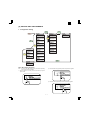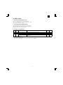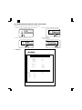
1
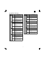
AR-PB8
CODE: 00ZARPB8//A1E
DIGITAL COPIER
OPTION PRINTER
EXPANSION KIT
MODEL
AR-PB8
CONTENTS
[ 1 ] SYSTEM CONFIGURATION . . . . . . . . . . . . . . . . . . . . . . . . . . . . 1-1
[ 2 ] SPECIFICATIONS . . . . . . . . . . . . . . . . . . . . . . . . . . . . . . . . . . . . 1-1
[ 3 ] SETUP . . . . . . . . . . . . . . . . . . . . . . . . . . . . . . . . . . . . . . . . . . . . . 3-1
[ 4 ] SETTING AND ADJUSTMENTS . . . . . . . . . . . . . . . . . . . . . . . . . 4-1
[ 5 ] SIMULATION . . . . . . . . . . . . . . . . . . . . . . . . . . . . . . . . . . . . . . . . 5-1
[ 6 ] CONFIGURATION REPORT AND TEST PAGE . . . . . . . . . . . . . 6-1
[ 7 ] FIRMWARE VERSION UP . . . . . . . . . . . . . . . . . . . . . . . . . . . . . 7-1
[ 8 ] TROUBLE CODE LIST . . . . . . . . . . . . . . . . . . . . . . . . . . . . . . . . 8-1
[ 9 ] CIRCUIT DIAGRAM . . . . . . . . . . . . . . . . . . . . . . . . . . . . . . . . . . . 9-1
Parts marked with “ ” is important for maintaining the safety of the set. Be sure to replace these parts with specified ones
for maintaining the safety and performance of the set.
SHARP CORPORATION
This document has been published to be used
for after sales service only.
The contents are subject to change without notice.
AR-PB8
CONTENTS
[ 1 ] SYSTEM CONFIGURATION . . . . . . . . . . . . . . . 1-1
[ 2 ] SPECIFICATIONS . . . . . . . . . . . . . . . . . . . . . . . . 1-1
5. Network Interface Control PWB installation . . . 3-3
6. INSTALLING THE PRINTER DRIVER . . . . . . . 3-4
1. Basic specifications . . . . . . . . . . . . . . . . . . . . . . 1-1
A. Installing onto Windows 95 . . . . . . . . . . . . . 3-4
2. Printer driver specifications . . . . . . . . . . . . . . . . 1-2
B. Installing onto Windows 98 . . . . . . . . . . . . . 3-5
A. System . . . . . . . . . . . . . . . . . . . . . . . . . . . . . 1-2
C. Installing onto Windows 95/98
without Using the Plug & Play Function . . . . 3-6
B. Kinds of printer drivers . . . . . . . . . . . . . . . . . 1-2
C. Set content . . . . . . . . . . . . . . . . . . . . . . . . . . 1-2
D. Option . . . . . . . . . . . . . . . . . . . . . . . . . . . . . . 1-3
(1) LCD kit . . . . . . . . . . . . . . . . . . . . . . . . . . 1-3
a. LCD message . . . . . . . . . . . . . . . . . . . 1-3
b. LED display . . . . . . . . . . . . . . . . . . . . 1-3
c. Operation keys . . . . . . . . . . . . . . . . . . 1-3
(2) Network board . . . . . . . . . . . . . . . . . . . . 1-4
(3) PS kit . . . . . . . . . . . . . . . . . . . . . . . . . . . 1-4
E. Expansion memory . . . . . . . . . . . . . . . . . . . . 1-4
F. PC environment . . . . . . . . . . . . . . . . . . . . . . 1-4
G. Paper handling specifications . . . . . . . . . . . 1-4
(1) Paper feed direction . . . . . . . . . . . . . . . . 1-4
a. Paper size and image transport
direction . . . . . . . . . . . . . . . . . . . . . . . 1-4
D. Installing onto Windows NT 4.0 . . . . . . . . . . 3-7
E. Changing Printer Configuration Settings . . . 3-7
[ 4 ] SETTING AND ADJUSTMENTS . . . . . . . . . . . . 4-1
1. Configuration setting . . . . . . . . . . . . . . . . . . . . . 4-1
A. Main Menu . . . . . . . . . . . . . . . . . . . . . . . . . . 4-2
B. Network Menu . . . . . . . . . . . . . . . . . . . . . . . 4-2
C. Interface Menu . . . . . . . . . . . . . . . . . . . . . . . 4-2
D. Test Menu . . . . . . . . . . . . . . . . . . . . . . . . . . 4-2
E. PS2 Menu . . . . . . . . . . . . . . . . . . . . . . . . . . 4-2
[ 5 ] SIMULATION . . . . . . . . . . . . . . . . . . . . . . . . . . . . 5-1
1. Entering the simulation mode . . . . . . . . . . . . . . 5-1
2. Cancelling the simulation mode . . . . . . . . . . . . 5-1
3. Contents of simulations . . . . . . . . . . . . . . . . . . 5-1
(2) Paper feed port . . . . . . . . . . . . . . . . . . . . 1-5
[ 6 ] CONFIGURATION REPORT AND
TEST PAGE . . . . . . . . . . . . . . . . . . . . . . . . . . . . . . 6-1
(3) Tray selection . . . . . . . . . . . . . . . . . . . . . 1-5
1. Samples . . . . . . . . . . . . . . . . . . . . . . . . . . . . . . 6-2
(4) Duplex print operation . . . . . . . . . . . . . . 1-5
2. Items and contents . . . . . . . . . . . . . . . . . . . . . . 6-2
a. Tablet operation . . . . . . . . . . . . . . . . . 1-5
A. Hardware status . . . . . . . . . . . . . . . . . . . . . . 6-2
b. Booklet operation . . . . . . . . . . . . . . . . 1-5
[ 7 ] FIRMWARE VERSION UP . . . . . . . . . . . . . . . . . 7-1
H. Print Area . . . . . . . . . . . . . . . . . . . . . . . . . . . 1-6
1. Cases where flash memory rewriting is required 7-1
I. Print reference . . . . . . . . . . . . . . . . . . . . . . . 1-7
2. Necessary tools . . . . . . . . . . . . . . . . . . . . . . . . 7-1
J. Font . . . . . . . . . . . . . . . . . . . . . . . . . . . . . . . 1-7
3. Procedure . . . . . . . . . . . . . . . . . . . . . . . . . . . . . 7-1
(1) For PCL . . . . . . . . . . . . . . . . . . . . . . . . . 1-7
[ 8 ] TROUBLE CODE LIST . . . . . . . . . . . . . . . . . . . . 8-1
(2) For PS2 . . . . . . . . . . . . . . . . . . . . . . . . . . 1-7
[ 9 ] CIRCUIT DIAGRAM . . . . . . . . . . . . . . . . . . . . . . . 9-1
[ 3 ] SET UP . . . . . . . . . . . . . . . . . . . . . . . . . . . . . . . . . . 3-1
1. BLOCK DIAGRAM . . . . . . . . . . . . . . . . . . . . . . 9-1
1. Procedures on the copier (operation panel) . . . 3-1
2. CIRCUIT DIAGRAM . . . . . . . . . . . . . . . . . . . . . 9-2
A. Copier operation panel disassembly . . . . . . 3-1
B. Cover disassembly . . . . . . . . . . . . . . . . . . . . 3-1
C. Printer operation panel installation . . . . . . . . 3-1
2. Procedures on the copier (rear side) . . . . . . . . 3-1
A. Copier rear cabinet disassembly . . . . . . . . . 3-1
B. Copier shield plate disassembly . . . . . . . . . . 3-2
C. PWB fixing plate installation . . . . . . . . . . . . . 3-2
D. Printer PWB installation . . . . . . . . . . . . . . . . 3-2
E. Mother board installation
(Packed together with the LCD kit.) . . . . . . . 3-2
F. Shield plate installation . . . . . . . . . . . . . . . . . 3-2
G. PWB cover installation . . . . . . . . . . . . . . . . . 3-3
3. Expansion memory installation . . . . . . . . . . . . . 3-3
4. PS kit (AR-PS1) installation . . . . . . . . . . . . . . . 3-3
Note for descriptions
The marks of ∗A and ∗B used in this Service Manual
indiciate that the marked functions are not supported as of
February 1999.
AR-PB8
[1] SYSTEM CONFIGURATION
LCD panel kit
(AR-PA1)
PS2 expansion kit
(AR-PS1)
Printer expansion kit
(AR-PB8)
Print server card
Expansion memory
(Commercially available 168 pin EDO DIMM: 16MB/32MB/64MB)
AR-160/200 Series
[2] SPECIFICATIONS
1. Basic specifications
Item
Contents
Item
Contents
Paper size
600 dpi, 300 dpi (1,200 dpi equivalent by
smoothing)
11" × 17", 8.5" ×
14", 8.5" × 11", 8.5"
Tray 1 ∼ 4∗ Inch series
× 11"R, 8.5" × 5.5",
8.5" × 13"
Paper exit
Face down system
Available
Shifter
Available (only in the model with the shifter)
Duplex print
Available (Only in the model with duplex
function)
Page description
PCL6 emulation
language (standard) PCL5e emulation
Dot emulation
None
Paper feed tray
Multi bypass tray
Tray 1, Tray 2, Tray 3, Tray 4 (Depends on
the machine and the option installation.)
Page protection
function
Available
Print speed
16 PPM (16cpm machine)
20 PPM (20cpm machine)
First print
7.2 sec
Resolution
Toner save
Multi bypass tray
Paper size
Tray 1 ∼ 4∗ AB series
A3, B4, A4R, B5R,
A5R, 11" × 17", 8.5"
× 14", 8.5" × 11"R,
8.5" × 5.5"R, 8.5" ×
13", 8.3" × 13",
7.25" × 10.5"R, DL,
C5, COM10
IEEE1284 port
Interface
Expansion slot
Interface cable
A3, B4, A4, A4R,
B5, B5R, A5
1–1
Nibble mode
Expansion slot for
Print Server Card × 1
Use IEEE1284 conforming parallel cable.
(shielded and grounded)
Max. length
∗ The number of trays supported depends on each model.
Compatibility mode
Within 3.0 m
AR-PB8
Item
C. Set content
Contents
Interface select
Auto
Emulation select
Auto
Plug and play
Conforming (only with Windows 95/98)
Item
∗A
Microsoft Windows 3.1
Microsoft Windows 98
Orientation
Portrait, Landscape
Document Style
1-Sided, 2-Sided(Book),
2-Sided(Tablet)∗B
Paper Source
Auto, Tray 1, Tray 2, Tray 3, Tray
4, Bypass Tray
Paper Size
A3 (297 × 420 mm), B4 (257 × 364
mm), A4 (210 × 297 mm), A5 (148
× 210 mm), B5 (182 × 257 mm),
Ledger (11" × 17"), Letter (8.5" ×
11"), Legal (8.5" × 14"), Executive
(7.25" × 10.5"), Folio (8.3" × 13"),
Invoice (5.5" × 8.5"), Foolscap
(8.5" × 13"), DL, C5, COM10,
Custom Paper
N-Up Printing
1-Up, 2-Up, 4-Up
Border
On, Off
Microsoft Windows
NT4.0
Macintosh OS (System
7.5 or later)
— ∗A
Network control
software
Sharp Admin Software
Built-in fonts
Outline Western language 31 fonts (PCL6
compatible)
Screen font
Outline European language 45 fonts (PCL6
compatible) for Windows
Outline European language 35 fonts (PS2
compatible) for Windows∗A
Memory
Fit to Page
On, Off
Standard
8MB
Page Protection
On, Off
Max.
136MB
Toner Save Mode
On, Off
Expansion slot
DIMM slot × 2
Smoothing
On, Off
Resolution Settings
600 dpi, 300 dpi
Graphics Mode
HP-GL/2 (Vector), Raster
Half Tone
Photo Images, Line Art, Scanned
Images
64MB, 32MB, 16MB
Expansion memory
(Commercialiy
(For details, refer to the
available 168 pin
descriptions below.)
EDO DIMM used)
Conforming PC
IBM PC-AT compatible
Apple Macintosh and compatible (AR-PS1
required)∗A
2. Printer driver specifications
Font Source
Resident Fonts, Download Fonts
True Type Mode
Download as True Type,
Download as bitmap font, Print as
graphics
Duplex Capability
Yes, No
Input Tray
One Tray, Two Trays, Three
Trays, Four Trays
Installed RAM
8MB, 24MB, 40MB, 56MB, 72MB,
88MB, 104MB, 136MB
A. System
OS
Microsoft Windows 3.1
IBM PC/AT
Macintosh
PCL5e
1 to 999
Microsoft Windows 95
Printer driver
PCL6
Copies
PCL
<AR-PB8>
∗A
PS2
<AR-PS1>
∗A
Microsoft Windows 95
∗A
Microsoft Windows 98
∗A
Microsoft Windows NT4.0
∗A
Macintosh OS (System
7.5 or later)
∗A
Unit
Set
Width
content of
custom
paper
Length
: Option
B. Kinds of printer drivers
Printer driver name
PCL5e for Windows 3.1∗A/95/98
PCL5e for Windows NT4.0
PCL6 for Windows 3.1∗A/95/98
PCL6 (PCL XL) or SPDL2 for Windows
NT4.0
PostScript Level2 for Windows
3.1/95/98∗A
PostScript Level2 for Windows NT4.0∗A
Name on PC screen
SHARP AR-160/200
Series PCL5e
SHARP AR-160/200
Series PS2
(AR-PS1)
PostScript Level2 for Macintosh OS∗A
1000 to 2969
(In the case of 0.1 mm)
394 to 1169 (In the case of 0.01")
1480 to 4318
(In the case of 0.1 mm)
583 to 1700 (In the case of 0.01")
Position
Depends on the paper size.
MAX Short –5.84" ∼ 5.84"
Long –8.5" ∼ 8.5"
Size
6 ∼ 900
Angle
±90˚
Set
content of Text
water
mark
Edit Fonts
SHARP AR-160/200
Series PCL6
0.01", 0.1 mm
TOP SECRET
CONFIDENTIAL
DRAFT
ORIGINAL
COPY
Refer to the following Font List.
Edit Density
0 ∼ 255
Transparent Text
Yes, No
On First Page Only Yes, No
As Outline Only
1–2
Yes, No (Only when Transparent
Text is OFF.)
AR-PB8
D. Option
Status
LCD display
(1) LCD kit
AR-PA1
Key
6 pcs.
(LINE, MENU, ITEM, ←, →, ENTER)
Lamp
2 (DATA, ONLINE)
Display
20 digits × 2 lines
Network
Menu ∗1
∗ When installing the AR-PB8 to a model which is not equipped with
the LCD panel, the LCD kit (AR-PA1) must be installed to.
a. LCD message
Status
LCD display
Online Online
Data Loss
Error
User
setting
Content
AUTO
Auto select to
emulation
PCL
PCL
PS2∗A
PS2∗A
HEX
HEX
PS2 Menu
∗2, ∗A
Interface
Menu
Clear Paper
Path
Main Menu
User
setting
Network
Menu ∗1
Enable/Disable
Netware
Enable EtherTalk
Enable/Disable
EtherTalk
Reset to Defaults
Reset Print Server
Card to default
Print PS2 Error
Setting of printing in
case of PS Error
I/O Time Out
If data reception is
not completed
within the set time,
it is judged as a
time out error.
Configuration Page
Configuration page
is printed.
When the paper
feed tray is
selected to AUTO.
Printing of the set
quantity is made.
Resolution
Printing at the set
resolution is made.
Smoothing
Smoothing function
setting.
Toner Save
Toner save mode
setting
Page Protection
Setting of page
protection function
2-Sided Printing∗B
Setting of duplex
function and
binding direction
Paper Source
Tray select
Paper Size
Paper size select
Orientation
Setting of print
direction
Emulation
Emulation setting
Set IP Address
IP address setting
is made.
Set Subnet Mask
Subnet Mask
setting is made.
Set Default
Gateway
Default Gateway
setting is made.
PS2 Font page is
printed∗A.
Extinguished
Indicates that the printer is
off-line and data cannot be
transferred or printed. Make
settings from the operation
panel in this mode. Note,
however, that you cannot make
settings if the “Data Remaining”
message is displayed.
Lit
Indicates that the printer is
on-line and data can be
transferred and printed.
Extinguished
Indicates that there is no data
being received or processed.
Lit
Indicates that the printer is
receiving or processing print
data.
Blinking
Indicates that there is print data
remaining in memory that has
not yet been printed.
ON LINE light
Paper jam
Paper exit tray full
Copies
PCL6 Font page is
printed.
b. LED display
Toner empty
Drum replacement
Cover open
Service call error
Check Panel
Enable Netware
∗1 When installing the network Interface card.
∗2 When installing the AR-PS1.
Tray 2 <Paper Size> When the paper
Tray 3 <Paper Size> feed tray is
Tray 4 <Paper Size> selected to other
than AUTO.
Bypass <Paper
Size>
Tray <Paper Size>
Enable/Disable
TCP/IP
PS2 Font Page
Tray 1 <Paper Size>
Error
Enable TCP/IP
Test Printing
PCL6 Font Page
Menu
Press ENTER
Memory Full Press ENTER
Paper Out
Content
DATA light
c. Operation keys
LINE key
Changes between the on-line and off-line
modes.
When the printer is on-line, it can receive data
from the computer with which it is connected.
When the printer is off-line, you can use
operation panel keys to make print settings.
Note, however, that you cannot make settings
if the "Data Remaining" message is displayed.
MENU key
Used to show setting menus on the display in
sequence.∗
ITEM key
Used to show the setting items of the selected
menu in sequence.∗
Left arrow key
Used to change the value of any item.∗
Right arrow key
ENTER key
Used to enter a new value.
∗ Invalid when the printer is on-line.
1–3
AR-PB8
(2) Network board
G. Paper handling specifications
10/100 Base TX
TCP/IP, IPX/SPX, Ether Talk, Jet Admin∗A
10 Base 2/T
TCP/IP, IPX/SPX, Ether Talk, Jet Admin∗A
(1) Paper feed direction
a. Paper size and image transport direction
(3) PS kit∗A
Model name
AR-PS1
Page description
language
PostScript level 2 emulation
Built-in fonts
Outline European 35 fonts (PS2 compatible)
Screen fonts
Outline European 35 fonts (PS2 compatible) for
Windows
Printer driver
Short side
A4
Long side
A4R
Short side
B5
Long side
B5R
Short side
A5
Long side
A5R
Short side
Ledger
Short side
Microsoft Windows 98
Legal
Short side
E. Expansion memory
Letter
Long side
LetterR
Short side
Invoice
Long side
InvoiceR
Short side
Foolscap
Short side
DIMM (60ns/EDO/168pin) (Use commercially
available one.)
Folio
Short side
Executive
Short side
64MB, 32MB, 16MB
COM-10
Short side
Vendor
Capacity
Model name
C5
Short side
Viking
Components
16MB
32MB
64MB
VE2641U2EN3-60
VE4641U4EN3-60
VE8641U4EN3-60
DL
Short side
Kingston
16MB
32MB
64MB
KTA4400/16
KTM4X64VN42-60EG
KTM8X64VN84-60EG
Simple
Technology
16MB
64MB
STI642004UD1-60VG
STI648104UD1-60VG
Transcend
16MB
32MB
32MB
64MB
TS2MLE64V6PN
TS4MLE64V6TN
TS4MLE64V6UN
TS8MLE64V6VN
Side set to the
= Long side
paper feed port
Transport direction
Side set to the
= Short side
paper feed port
Transport direction
ABC...
ABC...
Recommendable
product
Short side
B4
Microsoft Windows 95
Macintosh OS (System 7.5 or later)
Capacity
Side set to the paper feed port
A3
Microsoft Windows 3.1
Microsoft Windows NT4.0
Type
Paper Size
F. PC environment
Computer IBM PC/AT or compatible computer equipped with a
Type
bi-directional parallel interface and CD-ROM drive
For paper feed of the multi bypass tray, the short side must be set
to the paper fed port regardless of paper size for making print
data.
Operating
Windows 95, Windows 98, Windows NT4.0
System
CPU
Windows 95 : 486SX or better
Windows 98 : 486DX/66MHz or better (Pentium or
better is recommended.)
Windows NT4.0 : 486/25MHz or better
RAM
Windows 95 : 8MB or more (12MB or more is
recommended.)
Windows 98 : 16MB or more (32MB or more is
recommended.)
Windows NT4.0 : 16MB or more
1–4
AR-PB8
a. Tablet operation
Tablet means printing so that each page is aligned to be read
properly when binding the short edge of paper. Therefore, the
front page (odd number page) and the back page (even number
page) are in upside down each other. This reversion is mechanically made, and the printer software needs no additional process.
(2) Paper feed port
Tray kind
Bypass
Tray
Tray 1
Tray 2
Tray 3
Tray 4
Capacity
100
sheets
250
sheets
250
sheets
250
sheets
250
sheets
A3
B4
A4
A4R
B5
B5R
A5
A5R
Ledger
b. Booklet operation
Booklet means printing so that each page is aligned to be read
properly when binding the long edge of paper. Therefore, the front
page (odd number page) and the back page (even number page)
are in the same direction. This paper is reversed mechanically,
and the printer software needs to rotate the paper 180 degrees.
Legal
Letter
LetterR
Invoice
InvoiceR
Foolscap
Folio
Executive
COM-10
C5
DL
Custom
∗ The number of trays supported depends on each model.
∗ When printing with the multi bypass tray, the printer board cannot
recognize the set paper direction, and therefore it regards that the
short side of paper would be set (vertical transport direction) to
make data.
Duplex transport availability by paper size
Paper size
A3
B4
A4R
B5
B5R
A5
A5R
Ledger
Legal
Letter
LetterR
Invoice
InvoiceR
Foolscap
Folio
Executive
COM-10
C5
DL
Custom
(3) Tray selection
Paper handling is controlled on the copier side. The printer board
sends the Video I/F command to the digital copier according to the
computer direction of the tray.
(4) Duplex print operation∗B
The basic operation of duplex is described below.
Paper exit is made in face down. After printing an even number page,
the former odd number page is printed.
HOST
Printer(Tablet)
Page2
HOST
PAGE
2
Page1
PAGE
2
Page1
PAGE
3
Page4
PAGE
3
Page4
PAGE
4
Page3
PAGE
4
Page3
PAGE
1
PAGE
1
Printer(Booklet)
Page2
Duplex
Note: 1. Since duplex printing cannot be made for the special paper
(Custom) and Invoice, the computer’s direction of Custom
or Duplex printing is ignored and simplex printing is made.
2. Since duplex printing cannot be made in the case of paper
feed from the multi bypass tray, the computer’s direction to
the multi bypass tray to make duplex printing is ignored
and simplex printing is made.
3. Since printing order differs in simplex printing and duplex
printing, the insert surface differs in simplex and duplex in
the case where there is a difference between the front and
the back, for example, the letter head.
1–5
AR-PB8
H. Print Area
H
H
Physical
Page
E
E
E
Printable
Area
D
Logical
Page
F
D
E
E
E
F
D
D
HP/GL
Picture
Frame
B
B
F
E
C
G
A
F
E
C
H
G
H
Physical
Page
Logical
Page
Printable
Area
HP/GL
Picture
Frame
A
Paper
size
A
B
C
D
E
F
G
H
PAPER
SIZE
A
B
C
D
E
F
G
H
A3
7014 9920 6730
142
100
300
6814
0
A3
9920 7014 9684
118
100
300
9720
0
B4
6070 8597 5786
142
100
300
5870
0
B4
8597 6070 8361
118
100
300
8397
0
A4
4960 7014 4676
142
100
300
4760
0
A4
7014 4960 6778
118
100
300
6814
0
B5
4298 6070 5770
142
100
300
4098
0
B5
6070 4298 5830
118
100
300
5870
0
A5
3508 4960 3224
142
100
300
3308
0
A5
4960 3508 4720
118
100
300
4760
0
Ledger
6600 10200 6300
150
100
300
6400
0
Ledger
8400 5100 8160
120
100
300
8200
0
Legal
5100 8400 4800
150
100
300
4900
0
Legal
8400 5100 8160
120
100
300
8200
0
Letter
5100 6600 4800
150
100
300
4900
0
Letter
6600 5100 6360
120
100
300
6400
0
Invoice
3300 5100 3000
150
100
300
3100
0
Invoice
5100 3300 2860
120
100
300
4900
0
Foolscap 5100 7800 4800
150
100
300
4900
0
Foolscap 7800 5100 7560
120
100
300
7600
0
4980 7800 4680
150
100
300
4780
0
7800 4980 7560
120
100
300
7600
0
Executive 4350 6300 4050
Folio
150
100
300
4150
0
Executive 6300 4350 6060
Folio
120
100
300
6100
0
COM-10
2474 5700 2174
150
100
300
2274
0
COM-10
5700 2474 3460
120
100
300
5500
0
C5
3826 5408 3542
142
100
300
3626
0
C5
5408 3826 5172
118
100
300
5208
0
DL
2598 5196 2314
142
100
300
2398
0
DL
5196 2598 4960
118
100
300
4996
0
(Unit: Dots/600DPI)
(Unit: Dots/600DPI)
∗ Top Margin
The set value is received from the digital copier and data are made
according to the set value.
∗ Left margin
Since the paper size sensor is not set, the digital copier does not
know the size and direction of paper inserted. Therefore, the left
margin is set according to the paper size indicated by the print data
sent from the computer, and printing is made. If the computer does
not specify the paper size or in the case of custom size, the left
margin is set according to the default paper size.
1–6
AR-PB8
I. Print reference
Font No.
This machine employs the center reference system.
Since the digital copier is not equipped with the paper size detection,
format is made not by the actual paper size but by the paper size
specified by the computer, and center distribution is made.
Origin
Actual paper size
ABCDEFGHIJKLMN
12345
abc
Paper feed direction
Size specified by the host computer
Center reference line
Font Name
33
Dutch 801 SWM
34
Dutch 801 Bold SWM
35
Dutch 801 Italic SWM
36
Dutch 801 Bold Italic SWM
37
Symbol SWA
38
Wingbats SWM
39
Fixed Pitch 810 Courier Bold SWC
40
Fixed Pitch 810 Courier Italic SWC
41
Fixed Pitch 810 Courier Bold Italic SWC
42
Fixed Pitch 850 Letter Gothic 12 pitch/text SWC
43
Fixed Pitch 850 Letter Gothic Bold 12 pitch/text SWC
44
Fixed Pitch 850 Letter Gothic Italic 12 pitch/text SWC
45
Line Printer
J. Font
(2) For PS2∗A
(1) For PCL
Font Name
TrueDoc Format 45 fonts
1 bitmap font
Font No.
Dutch 801 SWA
DutchTM 801 Bold SWA
Font Name
0
Fixed Pitch 810 Courier Roman SWC
Dutch 801 Italic SWA
1
DutchTM 801 SWC
Dutch 801 Bold Italic SWA
2
Dutch 801 Bold SWC
SwissTM 721 SWA
3
Dutch 801 Italic SWC
Swiss 721 Bold SWA
4
Dutch 801 Bold Italic SWC
Swiss 721 Oblique SWA
5
Zapf Humanist 601 SWC
Swiss 721 Bold Oblique SWA
6
Zapf Humanist 601 Bold SWC
Fixed Pitch 810 Courier® SWA
7
Zapf Humanist 601 Italic SWC
Fixed Pitch 810 Courier Bold SWA
8
Zapf Humanist 601 Bold Italic SWC
Fixed Pitch 810 Courier Italic SWA
9
Ribbon 131 SWC
Fixed Pitch 810 Courier Bold Italic SWA
10
Clarendon 701 Clarendon Condensed SWC
Symbol SWA
11
SwissTM 742 SWC
Century 702 Century Schoolbook SWA
12
Swiss 742 Bold SWC
Century 702 Century Schoolbook Italic SWA
13
Swiss 742 Italic SWC
Century 702 Century Schoolbook Bold SWA
14
Swiss 742 Bold Italic SWC
Century 702 Century Schoolbook Bold Italic SWA
15
Swiss 742 Condensed SWC
Revival 711 ITC Bookman SWA
16
Swiss 742 Condensed Bold SWC
Revival 711 ITC Bookman Italic SWA
17
Swiss 742 Condensed Italic SWC
Revival 711 ITC Bookman® Demi SWA
18
Swiss 742 Condensed Bold Italic SWC
Revival 711 ITC Bookman Demi Italic SWA
19
Incised 901 SWC
Swiss 721 Narrow Bold SWA
20
Incised 901 Bold SWC
Swiss 721 Narrow Bold Oblique SWA
21
Incised 901 Italic SWC
Swiss 721 Narrow SWA
22
Aldine 430 Original Garamond SWC
Swiss 721 Narrow Oblique SWA
23
Aldine 430 Original Garamond Bold SWC
Geometric 711 ITC Avant Garde Gothic® Book SWA
24
Aldine 430 Original Garamond Italic SWC
Geometric 711 ITC Avant Garde Gothic Book Oblique SWA
25
Aldine 430 Original Garamond Bold Italic SWC
Geometric 711 ITC Avant Garde Gothic Demi SWA
26
Audrey Two SWC
Geometric 711 ITC Avant Garde Gothic Demi Oblique SWA
27
Flareserif 821 SWC
Chancery 801 ITC Zapf Chancery® Medium Italic SWA
28
Flareserif 821 Extra Bold SWC
ITC Zapf Dingbats® SWA
29
Swiss 721 SWM
Zapf Calligraphic 801 SWA
30
Swiss 721 Bold SWM
Zapf Calligraphic 801 Bold SWA
31
Swiss 721 Oblique SWM
Zapf Calligraphic 801 Italic SWA
32
Swiss 721 Bold Oblique SWM
Zapf Calligraphic 801 Bold Italic SWA
1–7
AR-PB8
[3] SET UP
1. Procedures on the copier (operation panel)
∗ When installing the LCD panel kit simultaneonsly.
A. Copier operation panel disassembly
• Remove screws and connector, and remove
C. Printer operation panel installation
• Engage pawls and fix the printer operation panel with screw.
the operation
panel.
Then connect the flat cable to the connector.
B. Cover disassembly
• Remove screw and disengage pawls, and remove the cover.
2. Procedures on the copier (rear side)
A. Copier rear cabinet disassembly
• Remove screws and remove the rear cabinet.
3–1
AR-PB8
B. Copier shield plate disassembly
• Remove screws, and remove the shield plate.
D. Printer PWB installation
• Fix the printer PWB with screws.
• Before introduction of the Expansion memory, the PS PWB, or
the network PWB, this procedure must be performed.
E. Mother board installation (Packed together with
the LCD kit.)
• Insert the connectors and fix them, then connect the connectors of the copier to them.
C. PWB fixing plate installation
• Fix the plate with screws.
F. Shield plate installation
• Fix the shield plate with screws.
3–2
AR-PB8
G. PWB cover installation
• Install the PWB cover with screws.
4. PS kit (AR-PS1) installation
•
Fix the PS PWB with pawl.
∗Note: The DIMM connector and the PS-PWB are provided with
the reverse insertion protection key(notch). A strong push,
however, allows reverse insertion. Use great care of the
inserting direction.
3. Expansion memory installation
•
Fix the memory PWB with pawls.
5. Network Interface Control PWB
installation
•
3–3
Insert the network PWB into the printer PWB connector and fix
it with screws.
AR-PB8
•
6. INSTALLING THE PRINTER DRIVER
To use this printer with your computer, you must install the printer
driver.
Install the printer driver using the supplied SHARP Software CDROM. This kit is supplied with the following printer drivers:
• PCL6 for Windows 95/98
• PCL6 for Windows NT 4.0
• PCL5e for Windows 95/98
• PCL5e for Windows NT 4.0
Note: • It is recommended that you install the PCL6 printer
driver. If you have a problem printing from older
software using the PCL6 driver, remove it and install the
PCL5e driver.
• The printer driver data in the CD-ROM can be copied to
floppy disks.
1. Double-click “My Computer”, “Ar160_200” and
“Makedisk”.
2. Double-click “Makedisk.exe”.
3. Follow the on-screen instructions.
Before installation, make sure that:
•
•
•
•
•
•
•
You read the README.TXT file which is contained on the
SHARP Software CD-ROM. This file contains the information
and restrictions for using the printer.
The printer is connected properly with the computer or network.
The printer is loaded with paper.
The printer is turned on and on-line (the ON LINE light is lit).
You quit all application software that is running on your computer.
Your computer meets the following hardware and software requirements:
2)
3)
Computer Type
IBM PC/AT or compatible computer
equipped with a bi-directional parallel
interface and CD-ROM drive
Operating System Windows 95, Windows 98, Windows NT 4.0
CPU
Windows 95:
486SX or better
Windows 98:
486DX/66MHz or better
(Pentium or better is
recommended.)
Windows NT 4.0: 486/25MHz or better
RAM
Windows 95:
8MB or more (12MB or
more is recommended.)
Windows 98:
16MB or more (32MB or
more is recommended.)
Windows NT 4.0: 16MB or more
4)
5)
This procedure uses the following drive name in examples:
Drive R: CD-ROM drive (holds the CD-ROM containing the
printer drivers)
Change the drive name as required according to your environment.
A. Installing onto Windows 95
This printer is compatible with plug & play. If your computer is incompatible with plug & play or if you want to use this printer as a network
printer, refer to “Installing onto Windows 95/98 without Using the Plug
& Play Function”.
1) Turn the computer on and start Windows 95.
Note: Depending on which version of Windows you are using,
the display examples in this step may differ from those on
your system.
• Either the “Update Device Driver Wizard” window or the “New
Hardware Found” window may appear automatically.
Note: If neither the “Update Device Driver Wizard” window nor
the “New Hardware Found” window appear, refer to “Installing Windows 95/98 without Using the Plug & Play
Function”.
3–4
If the “Update Device Driver Wizard” window appears, click the
[Next] button and proceed to step 2).
If the “New Hardware Found” window appears, perform the
following steps:
<1> Choose “Driver from disk provided by hardware manufacturer” and click the [OK] button.
<2> When the “Install From Disk” window appears, insert the
SHARP Software CD-ROM into the CD-ROM drive, type
R:\English\WinXX and click the [OK] button.
<3> Choose the appropriate printer driver from those listed below
and click the [OK] button.
• PCL6 Printer Driver: SHARP AR-160/200 Series PCL6
• PCL5e Printer Driver: SHARP AR-160/200 Series PCL5e
Note: It is recommended that you install the PCL6 printer driver.
If you have a problem printing from older software using
the PCL6 driver,remove it and install the PCL5e driver.
<4> Proceed to step 5).
Search for the printer driver by clicking [Other Locations...] button.
Insert the SHARP Software CD-ROM into the CD-ROM drive, type
R:\English\WinXX and click the [OK] button.
After Windows finds the printer driver, click the [Finish] button to
continue the installation.
Note: In this step the PCL6 printer driver is installed automatically. If you want to install the PCL5e printer driver, refer to
“Installing onto Windows 95/98 without Using the Plug &
Play Function”.
Set the printer name.
<1> If you want to change the printer name, enter a new name in
the space provided.
<2> If the program displays, “Do you want your Windows-based
programs to use this printer as the default printer?”, check
“Yes”.
<3> Click the [Next] button.
AR-PB8
6) Print a test page by clicking the [Finish] button.
Note: If you check “No” and click the [Finish] button, the printer
does not print a test page after the installation.
• The printer driver installation begins.
3) Click the [Have Disk...] button.
4) Insert the SHARP Software CD-ROM into the CD-ROM drive, type
R:\English\WinXX, and click the [OK] button.
•
If the “Insert Disk” window appears, perform the following
steps:
<1> Click the [OK] button.
<2> When the “Copying Files” window appears, type
R:\English\WinXX and click the [OK] button.
7) When the test page is printed properly, click the [Yes] button.
• The printer is ready for printing.
5) Choose the appropriate printer driver from those listed below and
click the [Next] button.
• PCL6 Printer Driver: SHARP AR-160/200 Series PCL6
• PCL5e Printer Driver: SHARP AR-160/200 Series PCL5e
Note: It is recommended that you install the PCL6 printer driver.
If you have a problem printing from older software using
the PCL6 driver,remove it and install the PCL5e driver.
B. Installing onto Windows 98
This printer is compatible with plug & play. If your computer is incompatible with plug & play or if you want to use this printer as a network
printer, refer to “Installing onto Windows 95/98 without Using the Plug
& Play Function”.
1) Turn the computer on and start Windows 98.
• The “Add New Hardware Wizard” window appears automatically, click the [Next] button.
Note: If the “Add New Hardware Wizard” window does not appear in this step, refer to “Installing onto Windows 95/98
without Using the Plug& Play Function”.
6) After Windows finds the printer driver, click the [Next] button to
continue the installation.
7) Print a test page by clicking the [Finish] button.
Note: If you check “No” and click the [Finish] button, the printer
does not print a test page after the installation.
• The printer driver installation begins.
2) Display a list of all the printer drivers by checking “Display a list of
all the drivers in a specific location, ...” and clicking the [Next]
button.
8) When the test page is printed properly, click the [Yes] button.
• The printer is ready for printing.
3–5
AR-PB8
C. Installing onto Windows 95/98 without Using
the Plug & Play Function
Computers using Windows 95 or Windows 98 that are compatible
with plug & play can install the printer driver automatically. However,
if your computer is incompatible with plug & play, or if you want to use
this printer as a network printer, follow the procedure in this section.
The following steps use Windows 98 in display examples.
1) Turn the computer on and start Windows 95/98.
2) Click the Start menu, point to “Settings”, and choose “Printers”.
3) When the “Printers” window appears, double-click the “Add
Printer” icon.
4) Click the [Next] button.
5) If the screen for choosing the connection method appears, choose
the connection method and click the [Next] button.
9) Choose the port and click the [Next] button.
Note: This screen appears only if you selected “Network printer”
in step 5).
Note: This screen appears only when the computer is connected
to a network.
• When the printer is directly connected to the computer, choose
“Local printer”.
Otherwise, choose “Network printer”.
If you choose “Network printer” you must specify a network
path or queue name.
Contact your network administrator for details.
The following steps use the example of a local printer.
10)Set the printer name.
<1> If you want to change the printer name, enter a new name in
the space provided.
<2> If the program displays, “Do you want your Windows-based
programs to use this printer as the default printer?”, check
“Yes”.
<3> Click the [Next] button.
6) Click the [Have Disk...] button.
11)Print a test page by clicking the [Finish] button.
Note: If you check “No” and click the [Finish] button, the printer
does not print a test page after the installation.
• The printer driver installation begins.
7) Insert the SHARP Software CD-ROM into the CD-ROM drive, type
R:\English\WinXX, and click the [OK] button.
8) Choose the appropriate printer driver from those listed below and
click the [Next] button.
• PCL6 Printer Driver: SHARP AR-160/200 Series PCL6
• PCL5e Printer Driver: SHARP AR-160/200 Series PCL5e
Note: It is recommended that you install the PCL6 printer driver.
If you have a problem printing from older software using
the PCL6 driver,remove it and install the PCL5e driver.
12)When the test page is printed properly, click the [Yes] button.
• The printer is ready for printing.
3–6
AR-PB8
D. Installing onto Windows NT 4.0
1) Turn the computer on and start Windows NT.
2) Click the Start menu, point to “Settings”, and choose “Printers”.
3) When the “Printers” window appears, double-click the “Add
Printer” icon.
4) Choose “My Computer” or “Network printer server” and click the
[Next] button.
• The following steps use “My Computer” as an example.
For more information about using this printer as a network
printer, refer to the Windows NT 4.0 networking documentation.
9) Set the printer name.
<1> If you want to change the printer name, enter a new name in
the space provided.
<2> If the program displays, “Do you want your Windows-based
programs to use this printer as the default printer?”, check
“Yes”.
<3> Click the [Next] button.
5) Check the checkbox for the port you are using and click the [Next]
button.
10)Make the appropriate settings for your environment.
• When using print sharing, choose “Shared” and enter a share
name. If necessary for your environment, select Windows 95
from the list of operating systems.
•
If you are not using shared printing, choose “Not shared”.
6) Click the [Have Disk...] button.
After making the settings on this screen, click the [Next] button.
11)Print a test page by clicking the [Finish] button.
Note: If you check “No” and click the [Finish] button, the printer
does not print a test page after the installation.
• The printer driver installation begins.
7) Insert the SHARP Software CD-ROM into the CD-ROM drive, type
R:\English\WinNT and click the [OK] button.
12)When the test page is printed properly, click the [Yes] button.
• The printer is ready for printing.
E. Changing Printer Configuration Settings
8) Choose the appropriate printer driver from those listed below and
click the [Next] button.
• PCL6 Printer Driver:SHARP AR-160/200 Series PCL6
• PCL5e Printer Driver:SHARP AR-160/200 Series PCL5e
Note: It is recommended that you install the PCL6 printer driver.
If you have a problem printing from older software using
the PCL6 driver,remove it and install the PCL5e driver.
After installing the printer driver use the procedure in this section to
change the printer configuration settings. Also refer to the print driver
help for more information.
1. Click the Start menu, point to “Settings”, and choose “Printers”.
2. Right-click the appropriate printer and choose “Properties”
fromthe menu.
3. Click the Configuration tab and change the printer settings.
3–7
AR-PB8
[4] SETTING AND ADJUSTMENTS
1. Configuration setting
MENU
MENU
Main Menu
ONLINE
Network Menu
PS2 Menu
Copies
Set IP Address
Print PS2 Error
1*
No *
Off *
Resolution
MENU
ITEM
Test Printing Menu
Configuration Page
PCL6 Font List
ITEM
Set Subnet Mask
600 *
No *
Smoothing
Set Default Gateway
On *
No *
Toner Save
Enable TCP/IP
Off *
No *
Page Protection
Enable Netware
Off *
No *
2-Sided Printing
Enable EtherTalk
Off *
No *
Paper Source
Reset to Default
Auto *
No *
Paper Size
MENU
A4 *
PS2 Font List
Orientation
Portrait *
Emulation
Auto *
MENU
Interface Menu
I/O Time Out
60 second *
(Basic Menu Setting Procedure)
2) Press the MENU key repeatedly until the required menu appears.
Note: The menus and items displayed may be different depending
on the optional functions installed.
1) When the printer is not in use, press the ON LINE key to put the
printer off-line.
DATA
ON LINE
MENU
ITEM
ENT
DATA
ON LINE
MENU
ITEM
ENTER
3) Press the ITEM key repeatedly until the required item appears.
DATA
ON LINE
4–1
MENU
ITEM
ENT
AR-PB8
4) Press the Left or Right arrow key to change the setting.
• The current value is marked with an asterisk (∗).
Item
DATA
LINE
MENU
ITEM
ENTER
Paper Size
5) After choosing the required value, press the ENTER key.
• The new value is registered.
Orientation
DATA
NE
MENU
ITEM
ENTER
Emulation
Possible
Settings
A3
B4
A4∗
B5
A5
Ledger
Legal
Letter∗
Executive
Folio
Invoice
Foolscap
COM-10
DL
C5
Description
Sets the size of the paper where data
will be printed. If this size is different
from the paper size present in the tray,
the size set on the operation panel takes
precedence.
∗ Depending on where the printer was
purchased, the default value is either A4
or Letter.
Sets the page orientation for printing.
Specify “Portrait” to print the paper with
Portrait
its long side (longer edge) vertical.
Landscape Specify “Landscape” to print the paper
with its long side (longer edge)
horizontal.
Auto
PCL
Specifies the printer language used.
HEX
B. Network Menu
Item
Set IP Address
A. Main Menu
Item
Copies
Resolution
Possible
Settings
1 ∼ 999
600dpi
300dpi
Set Subnet Mask
Description
Sets how many copies to print.
Set Default Gateway
Sets the printing resolution.
Enable TCP/IP
Sets whether smoothing is done or not.
This function improves the appearance
of printed documents by smoothing the
angles and curves of images. This
allows printing at a higher apparent
On
Smoothing
resolution. For example, if the printer is
Off
set to 600dpi, resolution equivalent to
1200dpi can be achieved.
When printing image data, you may
need to select "Off" to achieve best
results.
Sets whether toner save mode is in
effect or not. This function prints slightly
On
Toner Save
fainter to save toner. This item is
Off
different from the copier “toner save
mode”.
Sets page protection. Page protection is
a function designed to prevent data loss
Page
On
errors when complex data is printed.
Protection
Off
This menu item is displayed only if the
installed printer memory is 24MB or
more.
2-Sided
On
Setting of duplex function and binding
Printing ∗B
Off
direction.
Sets the tray used for paper feeding.
Auto
Setting to “Auto” automatically selects
Tray 1
the paper tray loaded with the paper of
Paper
Tray 2∗
the size specified in the “Paper Size”
Source
Tray 3∗
item.
Tray 4∗
∗ The available settings reflect the
Bypass Tray
installed trays.
Enable Netware
Enable EtherTalk
Reset to Defaults
Setting Choice
Yes
No
Yes
No
Yes
No
YES
NO
YES
NO
YES
NO
YES
NO
Description
Sets the IP address.
Sets the subnet
mask.
Sets the default
gateway.
Enable/Disable
TCP/IP
Enable/Disable
Netware
Enable/Disable
EtherTalk
Reset Print Server
Card to default.
∗ Displayed only if the optional Network Interface Control card is
installed.
C. Interface Menu
Item
I/O Time Out
Setting Choice
1 second
:
60 second
:
999 second
Description
Sets I/O time-out. If
no data is received
within the preset
time, print
processing is ended.
D. Test Menu
Item
Configuration Page
PCL6 Font List
PS2 Font List∗1, ∗A
Description
Prints the configuration page.
Prints the PCL6 font list.
Prints the PS2 font list.
∗ 1 Displayed only when the PS Kit (AR-PS1) is installed.
E. PS2 Menu ∗A
Item
Print PS2 Error
Description
When set to “On”, PS error print is made.
∗ Displayed only when the PS Kit (AR-PS1) is installed.
4–2
AR-PB8
[5] SIMULATION
1. Entering the simulation mode
Perform the following procedure to enter the simulation mode.
Clear key → Interruption key → “0” key → Interruption key → Main
code → Start key → Sub code → Start key
2. Cancelling the simulation mode
When the all clear key is pressed, the simulation mode is cancelled.
When the interruption key is pressed, the process is interrupted and
the screen returns to the sub code entering display.
3. Contens of Simulations
Main
code
Sub
code
22
18
24
9
67
14
Contents
Details of operation
Printer counter display
Used to display the current printer counter value. ∗1
Printer counter clear
Used to clear the printer counter. ∗2
Printer Flash ROM
The machine enters the version up mode of the printer PWB flash ROM.
Data Download
For details, refer to the printer PWB flash ROM version up procedure
described later.
∗1: Each counter display method
To display 123456: 123 (0.75 sec) → Blank (0.35sec) → 456 (0.75 sec) → Blank (1.0 sec) → repetition
∗2: Display after clearing each counter
000 (0.75 sec) → Blank (0.35sec) → 000 (0.75 sec) → Blank (1.0 sec) → Repetition
5–1
Initial
value
Set range
AR-PB8
[6] CONFIGURATION REPORT AND TEST PAGE
To test print the configuration page and font list, use the following procedure:
1) Press the ON LINE key to switch the printer to the offline mode.
3) Press the ITEM key to display the required item.
DATA
DATA
ON LINE
MENU
ON LINE
ENTER
ITEM
2) Press the MENU key to display the Test Menu.
ITEM
4) Press the ENTER key.
The test page prints.
DATA
ON LINE
MENU
DATA
MENU
ITEM
ENT
NE
MENU
1. Samples
Printer Configuration Page
HARDWARE STATUS
Machine Information
Language:
English
Hardware Specs
Base Memory:
Total Memory:
Network Board:
8MB
8MB
Not Installed
Version Information
PCL6:
1.00
Input Paper Trays
-SizePaper Inserted
Letter (8.5x11)
Letter (8.5x11R)
Legal (8.5x14)
Ledger (11x17)
Bypass Tray:
Tray 1:
Tray 2:
Tray 3:
Tray 4:
KEY MENU STATUS
Main Menu
Copies:
Resolution:
Smoothing:
Toner Save:
Paper Source:
Paper Size:
Orientation:
Emulation:
Interface Menu
I/O Time Out
1
600dpi
On
Off
Auto
Letter (8.5x11)
Portrait
PCL
60 sec.
PCL is a registered trademark of Hewlett-Packard Cmpany. All other trademarks and copyrights are the property of their respective owners.
6–1
ITEM
ENTER
ENT
AR-PB8
Available Paper Size
2. Items and contents
Appearance on Configuration Page
A. Hardware status
(Machine information)
a. Language
Value:
(English/French/German/Italian/Dutch/Spanish/Swedish)
Example: English
Default:
Depends on the Destination setting
Description: Depends on the LCD display, the configuration page, and
the font list language.
Letter (8 1/2 × 11)
Letter/Long Edge Feed
Letter (8 1/2 × 11R)
Letter/Short Edge Feed
Legal (8 1/2 × 14)
Legal/Short Edge Feed
Ledger (11 × 17)
Ledger/Short Edge Feed
Executive (7 1/4 × 10 1/2)
(Hardware specifications)
a. Base memory
Value:
8MB
Example: 8MB
Default:
8MB
Description: Indicates the printer PWB base memory capacity.
b. Total memory
Value:
(8, 24, 40, 56, 72, 88, 104, 136MB)
Example: 8MB
Default:
8MB
Description: Indicates the printer PWB total memory capacity, which is
the total of the base memory and the option memory.
Executive/Short Edge Feed
Invoice (5 1/2 × 8 1/2)
Invoice/Long Edge Feed
Foolscap (8 1/2 × 13)
Foolscap/Short Edge Feed
A4
A4/Long Edge Feed
A4R
A4/Short Edge Feed
B5
B5/Long Edge Feed
B5R
B5/Short Edge Feed
B4
B4/Short Edge Feed
A3
A3/Short Edge Feed
A5
A5/Long Edge Feed
A6
A6/Short Edge Feed
(Unknown)
Other size (EXTRA)
(No Paper)
No paper availadle on this
tray.
(No Tray)
(Tray Open)
c. Network board
Value:
Example: Not Installed.
Default:
Not Installed.
Description: Ubducates the network board installation status.
Description
There is a problem with this
tray.
This tray is opened (except
Bypass-Tray) or Tray is lifting
up.
a. Manual paper feed tray
Value:
(Suitable paper size)
Example: Letter (8 1/2 × 11")
Default:
Depends on the size of paper set on the manual paper
feed tray.
Description: Indicates the size of paper set on the manual paper feed
tray. Depends on the paper size detected on the manual
paper feed tray. “Unclear” means that the paper size is
not detected. If there is no paper, no print is made here.
(Firmware version)
a. PCL6
Value:
#.##
Example: 1.00
Default:
Depends on the printer firmware version.
b. Tray1, tray 2, tray 3, tray 4
Value:
(Suitable paper size)
Example: Letter (8 1/2 × 11")
Default:
Depends on the paper tray configuration.
Description: Indicates the paper size configuration of tray 1, tray 2,
tray 3, tray 4.
6–2
AR-PB8
[7] FIRMWARE VERSION UP
1. Cases where flash memory rewriting is
required
In the following cases, the program in the printer control PWB flash
memory must be rewritten.
1) When a bug or other error is found
2) Data stored in the flash memory is destroyed or deleted.
3) When the flash memory is replaced.
2. Necessary tools
1) Computer (PC) <Operates on MS-DOS.>
2) Parallel cable
3) Program data file (xxx.BIN)
3. Procedure
1) Print the configuration list to check the firmware version.
Use the operation panel of the copier to perform the following
procedure.
ONLINE <off line> → MENU <Test Printing Menu> → ITEM <Configuration Page> → ENTER <The test page prints>
2) Connect the PC and the copier with the parallel cable.
3) Turn on the power
4) Execute SIM 67-14.
“Erase Flash Data?” is displayed on the LCD.
5) Press the ENTER key on the copier’s operation panel.
“Now Erasing” is displayed on the LCD.
6) After deletion of data, “Please Send Data” is displayed on the LCD
and the machine enters the ready state for data input.
7) Download the program file.
(Note) Never turn off the power during download.
Set the PC to DOS mode → Check that the display shows
READY. → Then type COPY /B xxx.BIN LPT1:
and press the enter key.
( : space)
8) The machine enters the data reception mode.
While “Writing” is displayed on the LCD, data are written into the
flash ROM.
9) When data reception and data writing into the flash ROM are
completed, the SUM check is automatically performed.
(Note) In case of an error, “Sum check Error” is displayed.
Turn off the power once, and repeat the procedures from 3).
10)If there is no problem on the result of the SUM check, “Complete”
is displayed on the LCD.
11)Turn off/on the power to print the configuration page with the
above procedures, and check the firmware version.
12)Perform printing on the PC side and check that printing is performed normally.
7–1
AR-PB8
[8] TROUBLE CODE LIST
Main Sub
code code
F9
00 Content
Detail
Cause
Check and
remedy
10
Content
Detail
Cause
Check and
remedy
80
Content
Detail
Cause
Check and
remedy
81
Content
Detail
Cause
Check and
remedy
Main Sub
code code
F9
82 Content
Detail of trouble
F9-∗∗∗ Communication trouble
between MCU and PRT.
Communication setup error, framing,
parity, protocol error
Printer PWB connector disconnection
Printer unit PWB MCU PWB harness
failure
Printer PWB mother board connector
pin breakage.
Printer PWB ROM defect, data failure
Check the connectors and harness of
the printer PWB and the MCU PWB.
Check grounding of the machine.
Check the ROM of the printer PWB.
Printer PWB trouble
Communication trouble between MCU
and PRT
Printer PWB connector disconnection
Printer unit PWB MCU PWB harness
failure
Printer PWB mother board connector
pin breakage.
Printer PWB ROM defect, data failure
Check the connectors and harness of
the printer PWB and the MCU PWB.
Check grounding of the machine.
Check the ROM of the printer PWB.
Printer PWB communication trouble
(protocol)
Communication trouble between MCU
and printer PWB (Protocol error)
Printer PWB connector disconnection
Printer PWB MCU PWB harness failure
Printer PWB mother board connector
pin breakage.
Printer PWB ROM defect, data failure
Check the connectors and harness of
the printer PWB and the MCU PWB.
Check grounding of the machine.
Check the ROM of the printer PWB.
Printer PWB communication trouble
(Parity)
Communication trouble between MCU
and printer PWB (Parity error)
Printer PWB connector disconnection
Printer PWB MCU PWB harness failure
Printer PWB mother board connector
pin breakage.
Printer PWB ROM defect, data failure
Check the connectors and harness of
the printer PWB and the MCU PWB.
Check grounding of the machine.
Check the ROM of the printer PWB.
Detail
Cause
Check and
remedy
84
Content
Detail
Cause
Check and
remedy
88
Content
Detail
Cause
Check and
remedy
8–1
Detail of trouble
Printer PWB communication trouble
(Overrun)
Communication trouble between MCU
and printer PWB (Overrun error)
Printer PWB connector disconnection
Printer PWB MCU PWB harness failure
Printer PWB mother board connector
pin breakage.
Printer PWB ROM defect, data failure
Check the connectors and harness of
the Printer PWB and the MCU PWB.
Check grounding of the machine.
Check the ROM of the Printer PWB.
Printer PWB communication trouble
(Framing)
Communication trouble between MCU
and printer PWB (Framing error)
Printer PWB connector disconnection
Printer PWB MCU PWB harness failure
Printer PWB mother board connector
pin breakage.
Printer PWB ROM defect, data failure
Check the connectors and harness of
the Printer PWB and the MCU PWB.
Check grounding of the machine.
Check the ROM of the Printer PWB.
Printer PWB communication trouble
(Time-out)
Communication trouble between MCU
and printer PWB (Time-out error)
Printer PWB connector disconnection
Printer PWB MCU PWB harness failure
Printer PWB mother board connector
pin breakage.
Printer PWB ROM defect, data failure
Check the connectors and harness of
the Printer PWB and the MCU PWB.
Check grounding of the machine.
Check the ROM of the Printer PWB.
AR-PB8
[9] CIRCUIT DIAGRAM
1. BLOCK DIAGRAM
14.318MHz
PDATA[7:0]
SCLK
PARACONN
MODECLK
22.22MHz
MODEIN
G/A (2)
44.44MHz
MASTERCLK
SYSAD[15:0]
MODEIN
CY2292
14.318MHz
CPU
SYSAD[53:33]
MBA[11:0]
RCS0_
MD[63:0]
SYSAD[31:0]
RAD[21:0]
SYSCMD[8:0]
2MB
NR4650
(Internal 133MHz)
SYSAD[63:0]
SYSAD[31:0]
Boot ROM
SYSAD[31:0]
RAD[21:1]
RAD[5:2]
EEPROM
RAM
SYSAD[31:0]
Code ROM 0
2MB
RAD[21:0]
MASTERCLK
RCS_[3:0]
RCS1_
RAS0
CAS[7:0]
8MB
MBRAS1
CAS[7:0]
DIMM168 64MB Max
MBRAS2
CAS[7:0]
DIMM168 64MB Max
SCLK
RAM
SYSAD[31:0]
Code ROM 1
DIMM72
MD[63:0]
RAD[21:0]
RCS2_
Optional
RAM
MA[11:0]
(AR-PS1)
G/A (1)
PIACS0_
RAS0 CAS[7:0]
MBRAS1 MBRAS2
PIACS1_
PIACS2_
LDT[15:0]
SYSAD[15:0]
LDT[7:0]
NETWORKCONN
Digital copier I/F
RAD2
VFCLK
D9001MFH
VFCLK
81.2376MHz
9–1
AR-PB8
AR-PB8
2. CIRCUIT DIAGRAM
A
C
B
E
D
CPU
SYSAD[63:0]
3.3V
IC1
R114
R113
R112
R115
R116
R117
R118
R119
R120
4
SYSCMD[8:0]
R173
R199
R305
R252
R174
R200
R306
R253
3.3V
4.7K
4.7K
4.7K
4.7K
4.7K
4.7K
4.7K
4.7K
4.7K
SYSCMD0
SYSCMD1
SYSCMD2
SYSCMD3
SYSCMD4
SYSCMD5
SYSCMD6
SYSCMD7
SYSCMD8
3.3V
R69
R67
R102
R222
R304
4.7K
4.7K
4.7K
4.7K
4.7K
3
R135
R161
R134
R162
R136
R163
R137
R164
R165
SYSADC0
SYSADC1
SYSADC2
SYSADC3
SYSADC4
SYSADC5
SYSADC6
SYSADC7
10
10
10
10
10
10
10
10
10
R175
3.3V
4.7K
4.7K
4.7K
4.7K
4.7K
4.7K
4.7K
4.7K
4.7K
34
193
125
172
33
192
126
173
SYSADC0
SYSADC1
SYSADC2
SYSADC3
SYSADC4
SYSADC5
SYSADC6
SYSADC7
63
58
55
40
37
32
25
20
17
SYSCMD0
SYSCMD1
SYSCMD2
SYSCMD3
SYSCMD4
SYSCMD5
SYSCMD6
SYSCMD7
SYSCMD8
12 SYSCMDP
102
119
113
46
94
99
EXREQ_
RLS_
READY_
VALIN_
VALOUT_
185
MASTERCLK
INTR0_
INTR1_
INTR2_
PARINTR_
R185
R186
3.3V
89
84
81
78
75
70
4.7K
4.7K
122
NMI_
VCCOK
COLDRES_
CPURES_
MODECLK
MODEIN
R307
4.7K
3.3V
3.3V
C18
C87
EXTRQST_
RELEASE_
RDRDY_
WRRDY_
VALIDIN_
VALIDOUT_
MASTERCLK
INT0_
INT1_
INT2_
INT3_
INT4_
INT5_
NMI_
171
145
150
45
114
VCCOK
COLDRES_
RESET_
MODECLK
MODEIN
137
140
IOOUT
IOIN
188
161
SYNCIN
SYNCOUT
181
VCCP
C88
0.1u 0.1u
22u
182
VSSP
2
3.3V
1
C16
C19
C85
C81
C95
C96
0.1u 0.1u 0.1u 0.1u
22u
A
B
9–2
22u
4
10
16
22
30
36
42
50
60
66
74
80
86
92
98
109
117
123
127
129
135
141
147
153
163
169
174
186
189
195
201
VCC
VCC
VCC
VCC
VCC
VCC
VCC
VCC
VCC
VCC
VCC
VCC
VCC
VCC
VCC
VCC
VCC
VCC
VCC
VCC
VCC
VCC
VCC
VCC
VCC
VCC
VCC
VCC
VCC
VCC
VCC
SYSAD0
SYSAD1
SYSAD2
SYSAD3
SYSAD4
SYSAD5
SYSAD6
SYSAD7
SYSAD8
SYSAD9
SYSAD10
SYSAD11
SYSAD12
SYSAD13
SYSAD14
SYSAD15
SYSAD16
SYSAD17
SYSAD18
SYSAD19
SYSAD20
SYSAD21
SYSAD22
SYSAD23
SYSAD24
SYSAD25
SYSAD26
SYSAD27
SYSAD28
SYSAD29
SYSAD30
SYSAD31
SYSAD32
SYSAD33
SYSAD34
SYSAD35
SYSAD36
SYSAD37
SYSAD38
SYSAD39
SYSAD40
SYSAD41
SYSAD42
SYSAD43
SYSAD44
SYSAD45
SYSAD46
SYSAD47
SYSAD48
SYSAD49
SYSAD50
SYSAD51
SYSAD52
SYSAD53
SYSAD54
SYSAD55
SYSAD56
SYSAD57
SYSAD58
SYSAD59
SYSAD60
SYSAD61
SYSAD62
SYSAD63
77
72
69
62
57
48
44
39
31
24
19
14
11
6
203
198
82
87
90
95
100
111
115
120
128
133
138
143
146
151
162
167
76
71
64
61
56
47
43
38
26
23
18
13
8
5
200
197
83
88
93
96
101
112
116
121
131
134
139
144
149
152
165
168
GND
GND
GND
GND
GND
GND
GND
GND
GND
GND
GND
GND
GND
GND
GND
GND
GND
GND
GND
GND
GND
GND
GND
GND
GND
GND
GND
GND
GND
GND
3
9
15
21
29
35
41
49
59
65
73
79
85
91
97
110
118
124
130
136
142
148
154
164
170
175
187
190
196
202
R145
R146
R147
R148
R149
R150
R151
R152
R153
R154
R155
R156
R157
R158
R159
R160
R236
R237
R238
R239
R240
R241
R242
R243
R244
R245
R246
R247
R248
R249
R250
R251
R182
R183
R184
R181
R187
R188
R189
R190
R191
R192
R193
R194
R195
R196
R197
R198
R254
R308
R255
R309
R256
R310
R311
R312
R313
R314
R315
R316
R317
R318
R319
R320
10
10
10
10
10
10
10
10
10
10
10
10
10
10
10
10
10
10
10
10
10
10
10
10
10
10
10
10
10
10
10
10
10
10
10
10
10
10
10
10
10
10
10
10
10
10
10
10
10
10
10
10
10
10
10
10
10
10
10
10
10
10
10
10
SYSAD0
SYSAD1
SYSAD2
SYSAD3
SYSAD4
SYSAD5
SYSAD6
SYSAD7
SYSAD8
SYSAD9
SYSAD10
SYSAD11
SYSAD12
SYSAD13
SYSAD14
SYSAD15
SYSAD16
SYSAD17
SYSAD18
SYSAD19
SYSAD20
SYSAD21
SYSAD22
SYSAD23
SYSAD24
SYSAD25
SYSAD26
SYSAD27
SYSAD28
SYSAD29
SYSAD30
SYSAD31
SYSAD32
SYSAD33
SYSAD34
SYSAD35
SYSAD36
SYSAD37
SYSAD38
SYSAD39
SYSAD40
SYSAD41
SYSAD42
SYSAD43
SYSAD44
SYSAD45
SYSAD46
SYSAD47
SYSAD48
SYSAD49
SYSAD50
SYSAD51
SYSAD52
SYSAD53
SYSAD54
SYSAD55
SYSAD56
SYSAD57
SYSAD58
SYSAD59
SYSAD60
SYSAD61
SYSAD62
SYSAD63
R85
R84
R83
R82
R81
R80
R79
R78
R124
R123
R122
R121
R131
R132
R133
R130
R143
R144
R212
R177
R178
R172
R180
R179
R214
R213
R211
R207
R206
R209
R208
R210
R111
R217
R216
R215
R221
R220
R219
R218
R272
R273
R274
R275
R276
R277
R278
R279
R303
R283
R282
R281
R280
R287
R257
R258
R259
R260
R261
R262
R263
R264
R265
R266
4.7K
4.7K
4.7K
4.7K
4.7K
4.7K
4.7K
4.7K
4.7K
4.7K
4.7K
4.7K
4.7K
4.7K
4.7K
4.7K
4.7K
4.7K
4.7K
4.7K
4.7K
4.7K
4.7K
4.7K
4.7K
4.7K
4.7K
4.7K
4.7K
4.7K
4.7K
4.7K
4.7K
4.7K
4.7K
4.7K
4.7K
4.7K
4.7K
4.7K
4.7K
4.7K
4.7K
4.7K
4.7K
4.7K
4.7K
4.7K
4.7K
4.7K
4.7K
4.7K
4.7K
4.7K
4.7K
4.7K
4.7K
4.7K
4.7K
4.7K
4.7K
4.7K
4.7K
4.7K
3.3V
4
3
2
1
NR4650
C
D
E
9–3
AR-PB8
A
AR-PB8
C
B
E
D
ASIC 1
SYSCMD[8:0]
SYSCMD0
SYSCMD1
SYSCMD2
SYSCMD3
SYSCMD4
SYSCMD5
SYSCMD6
SYSCMD7
SYSCMD8
4
120
10 107
10 106
10 105
119
VALOUT_
VALIN_
READY_
EXREQ_
RLS_
R73
R72
R71
INTR0_
INTR1_
INTR2_
NMI_
R70
R68
R103
R101
VCCOK
COLDRES_
CPURES_
R100
R99
R98
10
10
10
10
104
103
102
101
INTR0_
INTR1_
INTR2_
NMI_
VCCOK
CRST_
CPURST_
118
R94
257
SYNCEN_
VFCLK
SYNCEN_
262 VFCLK
HSYNC_
PAGE_
VDIN_
R95
R96
265
267 HSYNC_
PAGE_
268
VDATA_
10
10
74LVC08
4
4.7K
4.7K
4.7K
3.3V
3
11
10u
10u
C69
0.1u
C100
0.1u
RESET_
R66
10
122
108
121
R39
R74
PIACS0_
2
D
10
10
IC25A
74LVC74
3
Q
PIAWE_
PIARD_
WAIT
R322
5
NICCS_
10
CLK
Q
6
3.3V
MASTERCLK
IC25B
74LVC74
12
D
Q
11
IC26B
Q
R323
6
5
9
EETCS_
10
74LVC08
CLK
3.3V
4
3.3V
8
C101
3.3V
0.1u
C45
0.1u
C70 C76
0.1u 0.1u
IC27C
CY2292
IC24C
9
3.3V
8
5
10
C102
74LVC32
6
SCAN_EN
SCAN_TEST
DC2_TEST
TESTMODE
78 PLLVDD
3.3V
3.3V
134 ROMCS0_
133
132 ROMCS1_
131 ROMCS2_
ROMCS3_
269 ROMWE_
70
69
68
67
0.01u
10
10
L2
20K
R104
C60
13
C13 C9
75
R105
153
152 RAS0_
151 RAS1_
150 RAS2_
RAS3_
146 CAS0_
145 CAS1_
144
143 CAS2_
142 CAS3_
CAS4_
141 CAS5_
140 CAS6_
139 CAS7_
270
271 BUFOE_
BUFDIR
72
71 PLL_TEST
79 PLL_EN
VCOIN
76 CPOUT
RESET_
R38
R65
2
10
10
10
10
10
R60
R61
R62
R63
R64
RCS3_
ROMWE_
0.1u
MA0
MA1
MA2
MA3
MA4
MA5
MA6
MA7
MA8
MA9
MA10
MA11
136
135 MOE_
MWE_
BUFDIR
RESET_
1
10
10
10
10
10
10
10
10
C99
CL
R166
R168
R167
14
2
14.318MHz
GND
GND
10
4.7K
RCS0_
RCS1_
RCS2_
3.3V
PR
VCC
5 XTALOUT VCC
R169
R138
Q 6
3.3V
GA2CLK
8
10
9
1
7
6
MOE_
MWE_
CLK
MASTERCLK
10
2
3
74LVC08
D
IC28A
74LVC74
Q 5
1
X2
10
CL
1
8
2
8
74LVC04
GA1
1
IC26C
9
R26
R27
R23
R24
R28
R29
R11
R12
CAS0_
CAS1_
CAS2_
CAS3_
CAS4_
CAS5_
CAS6_
CAS7_
RESET_
IC24D
9
10
6
74LVC32
SYNCEN_
254
253
252
249
248
247
246
245
244
243
240
239
R25
RAS0_
RAS1_
RAS2_
IC27B
5
130
129
126
125
124
123
IC18
CPUCLK
SP_
SHUTDN_ CLKA
CLKB
S0
CLKC
S1
CLKD
XTALIN XBUF
MPARREQ_
74LVC32
13
R125
15
16
12
13
4
11
PR
MASTERCLK
SCLK
113
PARREQ_
3
2
4
66
10
PIACS0_
PIACS1_
PIACS2_
PIACS3_
PIACS4_
PIACS5_
PIAWE_
PIARD_
WAIT
IC26D
12
MD[63:0]
IC17-2
MA0
MA1
MA2
MA3
MA4
MA5
MA6
MA7
MA8
MA9
MA10
MA11
IC27A
1
1
3.3V
SYSAD0
SYSAD1
SYSAD2
SYSAD3
SYSAD4
SYSAD5
SYSAD6
SYSAD7
SYSAD8
SYSAD9
SYSAD10
SYSAD11
SYSAD12
SYSAD13
SYSAD14
SYSAD15
SYSAD16
SYSAD17
SYSAD18
SYSAD19
SYSAD20
SYSAD21
SYSAD22
SYSAD23
SYSAD24
SYSAD25
SYSAD26
SYSAD27
SYSAD28
SYSAD29
SYSAD30
SYSAD31
SYSAD32
SYSAD33
SYSAD34
SYSAD35
SYSAD36
SYSAD37
SYSAD38
SYSAD39
SYSAD40
SYSAD41
SYSAD42
SYSAD43
SYSAD44
SYSAD45
SYSAD46
SYSAD47
SYSAD48
SYSAD49
SYSAD50
SYSAD51
SYSAD52
SYSAD53
SYSAD54
SYSAD55
SYSAD56
SYSAD57
SYSAD58
SYSAD59
SYSAD60
SYSAD61
SYSAD62
SYSAD63
CL
R93
274
275
276
277
278
279
280
283
284
285
286
287
288
289
292
293
2
3
4
5
6
7
8
11
12
13
14
15
16
17
20
21
22
23
24
25
26
29
30
31
32
33
34
35
40
41
42
43
44
45
46
47
50
51
52
53
54
55
56
57
60
61
62
63
PR
STS
CMD
DREQ0_
DREQ1_
DREQ2_
DREQ3_
10 95 DACK0_
94 DACK1_
93 DACK2_
92
DACK3_
266
TC_
263 RXD1
10 255 TXD1
4.7K 264 RXD2
256
TXD2
R97
PARACK_
POR_
117
4.7K116
4.7K115
4.7K114
R77
R76
R75
MA[11:0]
SYSAD[63:0]
SYSAD0
SYSAD1
SYSAD2
SYSAD3
SYSAD4
SYSAD5
SYSAD6
SYSAD7
SYSAD8
SYSAD9
SYSAD10
SYSAD11
SYSAD12
SYSAD13
SYSAD14
SYSAD15
SYSAD16
SYSAD17
SYSAD18
SYSAD19
SYSAD20
SYSAD21
SYSAD22
SYSAD23
SYSAD24
SYSAD25
SYSAD26
SYSAD27
SYSAD28
SYSAD29
SYSAD30
SYSAD31
SYSAD32
SYSAD33
SYSAD34
SYSAD35
SYSAD36
SYSAD37
SYSAD38
SYSAD39
SYSAD40
SYSAD41
SYSAD42
SYSAD43
SYSAD44
SYSAD45
SYSAD46
SYSAD47
SYSAD48
SYSAD49
SYSAD50
SYSAD51
SYSAD52
SYSAD53
SYSAD54
SYSAD55
SYSAD56
SYSAD57
SYSAD58
SYSAD59
SYSAD60
SYSAD61
SYSAD62
SYSAD63
4
3.3V
2
VALOUT_
VALIN_
READY_
EXREQ_
RLS_
10 98
10 97
10 96
RESET_
MPARREQ_
3
IC17-1
SYSCMD0
SYSCMD1
SYSCMD2
SYSCMD3
SYSCMD4
SYSCMD5
SYSCMD6
SYSCMD7
SYSCMD8
91
88
87
86
85
84
83
82
81
LDTOE_
74LVC04
C12
10u
77 PLLGND
10
19
28
36
37
38
49
59
65
73
80
90
100
110
111
112
128
138
147
159
168
177
184
185
186
196
205
214
224
233
242
251
258
259
260
273
282
291
294
295
GND
GND
GND
GND
GND
GND
GND
GND
GND
GND
GND
GND
GND
GND
GND
GND
GND
GND
GND
GND
GND
GND
GND
GND
GND
GND
GND
GND
GND
GND
GND
GND
GND
GND
GND
GND
GND
GND
GND
GND
MD0
MD1
MD2
MD3
MD4
MD5
MD6
MD7
MD8
MD9
MD10
MD11
MD12
MD13
MD14
MD15
MD16
MD17
MD18
MD19
MD20
MD21
MD22
MD23
MD24
MD25
MD26
MD27
MD28
MD29
MD30
MD31
MD32
MD33
MD34
MD35
MD36
MD37
MD38
MD39
MD40
MD41
MD42
MD43
MD44
MD45
MD46
MD47
MD48
MD49
MD50
MD51
MD52
MD53
MD54
MD55
MD56
MD57
MD58
MD59
MD60
MD61
MD62
MD63
238
236
234
230
228
226
221
219
217
215
211
209
207
203
201
199
197
193
191
189
183
181
179
175
173
171
169
165
163
161
157
155
237
235
231
229
227
225
220
218
216
212
210
208
206
202
200
198
194
192
190
188
182
180
178
174
172
170
166
164
162
160
156
154
VCC
VCC
VCC
VCC
VCC
VCC
VCC
VCC
VCC
VCC
VCC
VCC
VCC
VCC
VCC
VCC
VCC
VCC
VCC
VCC
VCC
VCC
VCC
VCC
VCC
VCC
VCC
VCC
VCC
VCC
VCC
VCC
VCC
VCC
1
9
18
27
39
48
58
64
74
75
89
99
109
127
137
148
149
158
167
176
187
195
204
213
222
223
232
241
250
261
272
281
290
296
MD0
MD1
MD2
MD3
MD4
MD5
MD6
MD7
MD8
MD9
MD10
MD11
MD12
MD13
MD14
MD15
MD16
MD17
MD18
MD19
MD20
MD21
MD22
MD23
MD24
MD25
MD26
MD27
MD28
MD29
MD30
MD31
MD32
MD33
MD34
MD35
MD36
MD37
MD38
MD39
MD40
MD41
MD42
MD43
MD44
MD45
MD46
MD47
MD48
MD49
MD50
MD51
MD52
MD53
MD54
MD55
MD56
MD57
MD58
MD59
MD60
MD61
MD62
MD63
B
9–4
C
C8
C44
0.1u 0.1u 10u
10u
1
E
9–5
2
C7
C59
GA1
D
3
3.3V
0.1u
A
4
AR-PB8
A
AR-PB8
C
B
E
D
ASIC 2
SV
R126
R127
R128
R129
4
4
R176
56
57
10
PARREQ_
PD ACK_
PDREQ_
R223
7
10
PARINTR_
CPUINTR_
1.2K
1.2K
1.2K
1.2K
IC19
PARACK_
IC20
38
37
36
35
INIT_
SLCTIN_
AUTOFD_
STB_
18
16
14
12
1Y1
1A3
1A4
1Y4
2Y1
9
7
5
3
RAD[21:1]
1A1
1A2
1Y2
1Y3
2A1
2Y2
2A2
2A3
2Y3
2Y4
13
14
15
16
RAD2
RAD3
RAD4
RAD5
ADR2
ADR3
ADR4
ADR5
1
2A4
R139
R140
R141
R142
6
8
22
22
22
22
INIT_
SLCTIN_
AUTOFD_
STB_
11
13
C80
C79
C78
C77
100p
100p
100p
100p
15
17
20
10
1G
2G
19
2
4
5V
74LS244
SYSAD[15:0]
C71
64
65
66
67
SYSAD0
SYSAD1
SYSAD2
SYSAD3
SYSAD4
3
68
SYSAD5
70
SYSAD6
SYSAD7
71
73
SYSAD8
74
SYSAD9
SYSAD10
75
77
SYSAD11
78
79
SYSAD12
SYSAD13
SYSAD14
SYSAD15
2
3
4
CPUD1
CPUD2
CPUD3
CPUD4
CPUD5
CPUD6
CPUD7
IC21
ACK_
BUSY
PE
FAULT_
CPUD8
CPUD10
CPUD11
CPUD14
CPUD15
R231
10K
R234
R235
10K
10K
R228
10K
2
5V
10K
R232
R233
R227
10K
R229
10K
BSEL0
BSEL1
BSEL2
BSEL3
BSEL4
PARAD0
PARAD1
PARAD2
PARAD4
PARAD5
PARAD6
PARAD7
100p
100p
100p
100p
100p
5V
5V
50
49
47
18
17
16
46
15
45
14
43
13
42
12
39
11
53
B1
B2
A1
A2
B3
A3
B4
B5
B6
A4
B7
A7
B8
A8
A5
A6
2
3
4
R41
R42
R43
22
22
22
5
6
R44
R45
22
22
7
R46
R47
R48
22
22
22
8
9
20
10
G
DIR
19
PDATA[7:0]
0.1u
1
SCANEN
5V
C53
C52
C51
C50
C49
C48
C47
C46
100p
100p
100p
100p
100p
100p
100p
100p
PD A TA0
PD A TA1
PD A TA2
PD A TA3
PD A TA4
PD A TA5
PD A TA6
PD A TA7
54
55
2
SCANTEST
C39
17
18
19
20
21
READY_
CRDY_
PSON_
NETON_
EX ON_
3.3V
VDD
VDD
VDD
VDD
R230
20
10
74LS245
IC23
3.3V
2Y4
C61
REV_
NETON_
3.3V
C62
IC22
RES_
MODECLK
VCCOK
MODEIN
10K
EREADY_
CRDY_
3.3V
C63
1.2K
1.2K
1.2K
10K
10K
10K
C64
R30
R31
R32
R203
R202
R201
29
28
27
26
25
10K
10K
C65
1.2K
1.2K
1.2K
R204
3
C66
74LS244
DEVCS_
DEVWR_
DEVRD_
PARAD3
R205
3.3V
22
1.2K
6
10
22
R110
1.2K
R224
R109
ACK_
BUSY
PE
FAULT_
SLCT
3
1G
2G
19
22
22
22
7
5
2Y3
2A4
1
CPUD12
CPUD13
2Y2
12
9
R106
R107
R108
R33
R34
R35
VCCOK
MODEIN
A0
A1
A2
GND
2A2
2A3
15
17
CPUD9
1Y4
2Y1
2A1
13
16
14
1Y2
1Y3
1A3
1A4
11
SLCT
18
1Y1
R36
5
63
MODECLK
8
VCC
7
TEST
6
SCK
5
SDA
1A1
1A2
62
RESET_
1
2
3
4
2
4
6
8
34
33
32
31
30
R37
59
60
61
PIACS0_
PIAWE_
PIARD_
0.1u
CPUD0
22
23
24
10K
SCK
VDD
SDAOUT
SDAIN
VDD
1
40
0.1u
3.3V
41
48
72
80
24C16
C17
C97
C89
C86
0.1u
0.1u
0.1u
R226
R225
R7
SRDY_
PREADY_
DUMMY
10
22
22
22
9
8
22u
SRDY_
EREADY_
DUMMY
GND
GND
GND
58
GA2CLK
GND
SCLK
GND
GND
11
12
44
51
52
69
76
GND
1
1
GA2
A
B
9–6
C
D
E
9–7
AR-PB8
A
B
AR-PB8
C
D
E
MEMORY BUFFER
SYSAD[63:0]
MBA[11:0]
RAD[21:1]
3.3V
47
46
44
43
41
40
38
37
36
35
33
32
30
29
27
26
1A1
1A2
1A3
1A4
2A1
2A2
2A3
2A4
3A1
3A2
3A3
3A4
4A1
4A2
4A3
4A4
1
48
25
24
1OE_
2OE_
3OE_
4OE_
7
18
31
42
VCC
VCC
VCC
VCC
CPWBX0034QS51
MA[11:0]
IC10
SYSAD33
SYSAD34
SYSAD35
SYSAD36
SYSAD37
SYSAD38
SYSAD39
SYSAD40
SYSAD41
SYSAD42
SYSAD43
SYSAD44
SYSAD45
SYSAD46
SYSAD47
SYSAD48
4
1Y1
1Y2
1Y3
1Y4
2Y1
2Y2
2Y3
2Y4
3Y1
3Y2
3Y3
3Y4
4Y1
4Y2
4Y3
4Y4
GND
GND
GND
GND
GND
GND
GND
GND
2
3
5
6
8
9
11
12
13
14
16
17
19
20
22
23
R271
R302
R301
R300
R299
R298
R297
R296
R295
R294
R293
R292
R291
R290
R289
R288
10
10
10
10
10
10
10
10
10
10
10
10
10
10
10
10
IC11
RAD1
RAD2
RAD3
RAD4
RAD5
RAD6
RAD7
RAD8
RAD9
RAD10
RAD11
RAD12
RAD13
RAD14
RAD15
RAD16
MA0
MA1
MA2
MA3
MA4
MA5
MA6
MA7
MA8
MA9
MA10
MA11
RAS1_
RAS2_
MWE_
MOE_
4
10
15
21
28
34
39
45
47
46
44
43
41
40
38
37
36
35
33
32
30
29
27
26
1
48
25
24
3.3V
7
18
31
42
74LVC16244
C94
3
1A1
1A2
1A3
1A4
2A1
2A2
2A3
2A4
3A1
3A2
3A3
3A4
4A1
4A2
4A3
4A4
1Y1
1Y2
1Y3
1Y4
2Y1
2Y2
2Y3
2Y4
3Y1
3Y2
3Y3
3Y4
4Y1
4Y2
4Y3
4Y4
1OE_
2OE_
3OE_
4OE_
GND
GND
GND
GND
GND
GND
GND
GND
VCC
VCC
VCC
VCC
2
3
5
6
8
9
11
12
13
14
16
17
19
20
22
23
R86
R87
R88
R89
R90
R91
R92
R49
R50
R51
R52
R53
R54
R55
R56
R57
10
10
10
10
10
10
10
10
10
10
10
10
10
10
10
10
4
MBA0
MBA1
MBA2
MBA3
MBA4
MBA5
MBA6
MBA7
MBA8
MBA9
MBA10
MBA11
MBRAS1_
MBRAS2_
MBWE_
MBOE_
4
10
15
21
28
34
39
45
74LVC16244
0.1u
C55
3
0.1u
IC12
SYSAD49
SYSAD50
SYSAD51
SYSAD52
SYSAD53
ROMWE_
BUFDIR
2
4
6
8
11
13
15
17
1
19
1A1
1A2
1A3
1A4
2A1
2A2
2A3
2A4
1Y1
1Y2
1Y3
1Y4
2Y1
2Y2
2Y3
2Y4
1G
2G
VCC
GND
18
16
14
12
9
7
5
3
20
10
R267
R268
R269
R270
R286
R285
R284
10
10
10
10
10
10
10
RAD17
RAD18
RAD19
RAD20
RAD21
FWE_
ROE_
3.3V
74LVC244
SYSAD[15:0]
C93
LDT[15:0]
IC13
0.1u
SYSAD0
SYSAD1
SYSAD2
SYSAD3
SYSAD4
SYSAD5
SYSAD6
SYSAD7
SYSAD8
SYSAD9
SYSAD10
SYSAD11
SYSAD12
SYSAD13
SYSAD14
SYSAD15
2
47
46
44
43
41
40
38
37
36
35
33
32
30
29
27
26
1
24
48
25
PIARD_
LDTOE_
3.3V
7
18
31
42
1B1
1B2
1B3
1B4
1B5
1B6
1B7
1B8
2B1
2B2
2B3
2B4
2B5
2B6
2B7
2B8
1A1
1A2
1A3
1A4
1A5
1A6
1A7
1A8
2A1
2A2
2A3
2A4
2A5
2A6
2A7
2A8
1DIR
2DIR
1OE_
2OE_
GND
GND
GND
GND
GND
GND
GND
GND
VCC
VCC
VCC
VCC
2
3
5
6
8
9
11
12
13
14
16
17
19
20
22
23
LDT0
LDT1
LDT2
LDT3
LDT4
LDT5
LDT6
LDT7
LDT8
LDT9
LDT10
LDT11
LDT12
LDT13
LDT14
LDT15
2
4
10
15
21
28
34
39
45
74LVC16245
C75
0.1u
1
1
A
B
9–8
C
E
D
9–9
AR-PB8
A
AR-PB8
B
C
D
E
ROM
SYSAD[63:0]
RAD[21:1]
IC2
RAD1
RAD2
RAD3
RAD4
RAD5
RAD6
RAD7
RAD8
RAD9
RAD10
RAD11
RAD12
RAD13
RAD14
RAD15
RAD16
RAD17
RAD18
RAD19
RAD20
RAD21
4
3.3V
3
32
28
27
26
25
24
23
22
20
19
18
17
13
12
11
10
8
7
6
5
4
A0
A1
A2
A3
A4
A5
A6
A7
A8
A9
A10
A11
A12
A13
A14
A15
A16
A17
A18
A19
A20
14
2
55
54
CE0_
CE1_
WE_
OE_
16
31
56
53
1
RP_
BYTE_
WP_
RY/BY_
3/5_
33
35
38
40
44
46
49
51
34
36
39
41
45
47
50
52
Vpp
Vcc
Vcc
Vcc
9
37
43
SYSAD0
SYSAD1
SYSAD2
SYSAD3
SYSAD4
SYSAD5
SYSAD6
SYSAD7
SYSAD8
SYSAD9
SYSAD10
SYSAD11
SYSAD12
SYSAD13
SYSAD14
SYSAD15
RAD1
RAD2
RAD3
RAD4
RAD5
RAD6
RAD7
RAD8
RAD9
RAD10
RAD11
RAD12
RAD13
RAD14
RAD15
RAD16
RAD17
RAD18
RAD19
RAD20
RAD21
15
NC 3
NC 29
NC 30
3.3V
32
28
27
26
25
24
23
22
20
19
18
17
13
12
11
10
8
7
6
5
4
14
2
55
54
C74
0.1u
3.3V
21
GND
42
GND
GND 48
16
31
56
53
1
LH28F800SUT
A0
A1
A2
A3
A4
A5
A6
A7
A8
A9
A10
A11
A12
A13
A14
A15
A16
A17
A18
A19
A20
CE0_
CE1_
WE_
OE_
RP_
BYTE_
WP_
RY/BY_
3/5_
D0
D1
D2
D3
D4
D5
D6
D7
D8
D9
D10
D11
D12
D13
D14
D15
33
35
38
40
44
46
49
51
34
36
39
41
45
47
50
52
SYSAD0
SYSAD1
SYSAD2
SYSAD3
SYSAD4
SYSAD5
SYSAD6
SYSAD7
SYSAD8
SYSAD9
SYSAD10
SYSAD11
SYSAD12
SYSAD13
SYSAD14
SYSAD15
15
Vpp
9
Vcc
37
Vcc
43
Vcc
3
NC
29
NC
30
NC
5V
3.3V
RAD1
RAD2
RAD3
RAD4
RAD5
RAD6
RAD7
RAD8
RAD9
RAD10
RAD11
RAD12
RAD13
RAD14
RAD15
RAD16
RAD17
RAD18
RAD19
RAD20
RAD21
12
13
14
15
16
17
18
28
31
32
29
33
34
36
65
66
67
68
69
70
71
C72
C73
40
41
42
43
0.1u
0.1u
44
21
GND
42
GND
48
GND
47
3.3V
LH28F800SUT
RCS3_
RCS0_
RCS1_
RCS2_
19
48
46
45
11
A0
A1
A2
A3
A4
A5
A6
A7
A8
A9
A10
A11
A12
A13
A14
A15
A16
A17
A18
A19
A20
1CE0_
1CE1_
2CE0_
2CE1_
OE_
WE_
RP
BYTE_
WP
RY/BY_
3/5_
D0
D1
D2
D3
D4
D5
D6
D7
D8
D9
D10
D11
D12
D13
D14
D15
D16
D17
D18
D19
D20
D21
D22
D23
D24
D25
D26
D27
D28
D29
D30
D31
SYSAD0
SYSAD1
SYSAD2
SYSAD3
SYSAD4
SYSAD5
SYSAD6
SYSAD7
SYSAD8
SYSAD9
SYSAD10
SYSAD11
SYSAD12
SYSAD13
SYSAD14
SYSAD15
SYSAD16
SYSAD17
SYSAD18
SYSAD19
SYSAD20
SYSAD21
SYSAD22
SYSAD23
SYSAD24
SYSAD25
SYSAD26
SYSAD27
SYSAD28
SYSAD29
SYSAD30
SYSAD31
2
3
4
5
6
7
8
9
21
22
23
24
25
26
27
35
37
38
49
50
51
52
53
54
56
57
58
60
59
62
63
64
55
VPP
10
VCC1
30
VCC1
61
VCC2
VSS1
VSS1
VSS1
VSS2
IC5
IC4
RAD1
RAD2
RAD3
RAD4
RAD5
RAD6
RAD7
RAD8
RAD9
RAD10
RAD11
RAD12
RAD13
RAD14
RAD15
RAD16
RAD17
RAD18
RAD19
RAD20
RAD21
32
28
27
26
25
24
23
22
20
19
18
17
13
12
11
10
8
7
6
5
4
14
2
55
54
3.3V
16
31
56
53
1
A0
A1
A2
A3
A4
A5
A6
A7
A8
A9
A10
A11
A12
A13
A14
A15
A16
A17
A18
A19
A20
CE0_
CE1_
WE_
OE_
RP_
BYTE_
WP_
RY/BY_
3/5_
D0
D1
D2
D3
D4
D5
D6
D7
D8
D9
D10
D11
D12
D13
D14
D15
33
35
38
40
44
46
49
51
34
36
39
41
45
47
50
52
15
Vpp
9
Vcc
37
Vcc
43
Vcc
3
NC
29
NC
30
NC
SYSAD16
SYSAD17
SYSAD18
SYSAD19
SYSAD20
SYSAD21
SYSAD22
SYSAD23
SYSAD24
SYSAD25
SYSAD26
SYSAD27
SYSAD28
SYSAD29
SYSAD30
SYSAD31
RAD1
RAD2
RAD3
RAD4
RAD5
RAD6
RAD7
RAD8
RAD9
RAD10
RAD11
RAD12
RAD13
RAD14
RAD15
RAD16
RAD17
RAD18
RAD19
RAD20
RAD21
3.3V
32
28
27
26
25
24
23
22
20
19
18
17
13
12
11
10
8
7
6
5
4
14
2
55
54
C92
0.1u
3.3V
21
GND
42
GND
48
GND
LH28F800SUT
16
31
56
53
1
A0
A1
A2
A3
A4
A5
A6
A7
A8
A9
A10
A11
A12
A13
A14
A15
A16
A17
A18
A19
A20
CE0_
CE1_
WE_
OE_
RP_
BYTE_
WP_
RY/BY_
3/5_
D0
D1
D2
D3
D4
D5
D6
D7
D8
D9
D10
D11
D12
D13
D14
D15
33
35
38
40
44
46
49
51
34
36
39
41
45
47
50
52
SYSAD16
SYSAD17
SYSAD18
SYSAD19
SYSAD20
SYSAD21
SYSAD22
SYSAD23
SYSAD24
SYSAD25
SYSAD26
SYSAD27
SYSAD28
SYSAD29
SYSAD30
SYSAD31
15
Vpp
9
Vcc
37
Vcc
43
Vcc
3
NC
29
NC
30
NC
1
20
39
72
RAD1
RAD2
RAD3
RAD4
RAD5
RAD6
RAD7
RAD8
RAD9
RAD10
RAD11
RAD12
RAD13
RAD14
RAD15
RAD16
RAD17
RAD18
RAD19
RAD20
RAD21
0.1u
C14
+
22u
12
13
14
15
16
17
18
28
31
32
29
33
34
36
65
66
67
68
69
70
71
40
41
42
43
44
47
3.3V
5V
3.3V
C67
FWE_
ROE_
2
CN2
CN1
IC3
D0
D1
D2
D3
D4
D5
D6
D7
D8
D9
D10
D11
D12
D13
D14
D15
19
48
46
45
11
A0
A1
A2
A3
A4
A5
A6
A7
A8
A9
A10
A11
A12
A13
A14
A15
A16
A17
A18
A19
A20
1CE0_
1CE1_
2CE0_
2CE1_
OE_
WE_
RP
BYTE_
WP
RY/BY_
3/5_
D0
D1
D2
D3
D4
D5
D6
D7
D8
D9
D10
D11
D12
D13
D14
D15
D16
D17
D18
D19
D20
D21
D22
D23
D24
D25
D26
D27
D28
D29
D30
D31
SYSAD0
SYSAD1
SYSAD2
SYSAD3
SYSAD4
SYSAD5
SYSAD6
SYSAD7
SYSAD8
SYSAD9
SYSAD10
SYSAD11
SYSAD12
SYSAD13
SYSAD14
SYSAD15
SYSAD16
SYSAD17
SYSAD18
SYSAD19
SYSAD20
SYSAD21
SYSAD22
SYSAD23
SYSAD24
SYSAD25
SYSAD26
SYSAD27
SYSAD28
SYSAD29
SYSAD30
SYSAD31
2
3
4
5
6
7
8
9
21
22
23
24
25
26
27
35
37
38
49
50
51
52
53
54
56
57
58
60
59
62
63
64
VSS1
VSS1
VSS1
VSS2
DIMM72
3
55
VPP
10
VCC1
30
VCC1
61
VCC2
5V
3.3V
C82
0.1u
4
1
20
39
72
C68
C14
+
C83
0.1u
22u
0.1u
DIMM72
2
5V
3.3V
C90
C91
0.1u
0.1u
21
GND
42
GND
48
GND
LH28F800SUT
1
1
A
B
9 – 10
C
D
E
9 – 11
AR-PB8
A
AR-PB8
B
C
D
E
DRAM
MBA[11:0]
MD[63:0]
CN3
IC6
MBA0
MBA1
MBA2
MBA3
MBA4
MBA5
MBA6
MBA7
MBA8
MBA9
MBA10
MBA11
4
RAS0_
CAS0_
CAS1_
MBWE_
MBOE_
3.3V
17
18
19
20
23
24
25
26
27
28
16
15
14
31
30
13
29
32
1
6
21
A0
A1
A2
A3
A4
A5
A6
A7
A8
A9
A10
A11
RAS_
LCAS_
UCAS_
WE_
OE_
NC
Vcc
Vcc
Vcc
16M16
3
CAS2_
CAS3_
TITLE
3.3V
17
18
19
20
23
24
25
26
27
28
16
15
14
31
30
13
29
32
1
6
21
MD0
MD1
MD2
MD3
MD4
MD5
MD6
MD7
MD8
MD9
MD10
MD11
MD12
MD13
MD14
MD15
2
3
4
5
7
8
9
10
33
34
35
36
38
39
40
41
12
11
37
22
42
MD16
MD17
MD18
MD19
MD20
MD21
MD22
MD23
MD24
MD25
MD26
MD27
MD28
MD29
MD30
MD31
C33
I/O1
I/O2
I/O3
I/O4
I/O5
I/O6
I/O7
I/O8
I/O9
I/O10
I/O11
I/O12
I/O13
I/O14
I/O15
I/O16
NC
NC
GND
GND
GND
2
3
4
5
7
8
9
10
33
34
35
36
38
39
40
41
12
11
37
22
42
MD32
MD33
MD34
MD35
MD36
MD37
MD38
MD39
MD40
MD41
MD42
MD43
MD44
MD45
MD46
MD47
0.1u
2
CAS4_
CAS5_
3.3V
17
18
19
20
23
24
25
26
27
28
16
15
14
31
30
13
29
32
1
6
21
A0
A1
A2
A3
A4
A5
A6
A7
A8
A9
A10
A11
RAS_
LCAS_
UCAS_
WE_
OE_
NC
Vcc
Vcc
Vcc
16M16
C38
I/O1
I/O2
I/O3
I/O4
I/O5
I/O6
I/O7
I/O8
I/O9
I/O10
I/O11
I/O12
I/O13
I/O14
I/O15
I/O16
NC
NC
GND
GND
GND
0.1u
IC9
MBA0
MBA1
MBA2
MBA3
MBA4
MBA5
MBA6
MBA7
MBA8
MBA9
MBA10
MBA11
1
CAS6_
CAS7_
3.3V
17
18
19
20
23
24
25
26
27
28
16
15
14
31
30
13
29
32
1
6
21
A0
A1
A2
A3
A4
A5
A6
A7
A8
A9
A10
A11
RAS_
LCAS_
UCAS_
WE_
OE_
NC
Vcc
Vcc
Vcc
16M16
A
C21
I/O1
I/O2
I/O3
I/O4
I/O5
I/O6
I/O7
I/O8
I/O9
I/O10
I/O11
I/O12
I/O13
I/O14
I/O15
I/O16
NC
NC
GND
GND
GND
2
3
4
5
7
8
9
10
33
34
35
36
38
39
40
41
12
11
37
22
42
MD48
MD49
MD50
MD51
MD52
MD53
MD54
MD55
MD56
MD57
MD58
MD59
MD60
MD61
MD62
MD63
28
29
46
47
112
113
130
131
MBWE_
27
48
MBOE_
31
44
R8
R6
R10
R9
R7
82
83
165
166
167
10K
10K
10K
10K
10K
21
22
24
25
42
50
51
52
53
61
62
63
79
80
81
105
106
108
109
111
114
115
125
126
128
129
132
134
135
136
137
145
146
147
163
164
1
12
23
32
43
54
64
78
85
96
107
116
127
138
148
162
A0
A1
A2
A3
A4
A5
A6
A7
A8
A9
A10
A11
A12
DQ0
DQ1
DQ2
DQ3
DQ4
DQ5
DQ6
DQ7
DQ8
DQ9
DQ10
DQ11
DQ12
DQ13
DQ14
DQ15
DQ16
DQ17
DQ18
DQ19
DQ20
DQ21
DQ22
DQ23
DQ24
DQ25
DQ26
DQ27
DQ28
DQ29
DQ30
DQ31
DQ32
DQ33
DQ34
DQ35
DQ36
DQ37
DQ38
DQ39
DQ40
DQ41
DQ42
DQ43
DQ44
DQ45
DQ46
DQ47
DQ48
DQ49
DQ50
DQ51
DQ52
DQ53
DQ54
DQ55
DQ56
DQ57
DQ58
DQ59
DQ60
DQ61
DQ62
DQ63
RAS0_
RAS2_
CAS0_
CAS1_
CAS2_
CAS3_
CAS4_
CAS5_
CAS6_
CAS7_
WE0_
WE2_
OE0_
OE2_
SDA
SCL
SA0
SA1
SA2
NC
NC
NC
NC
NC
NC
NC
NC
NC
NC
NC
NC
NC
NC
NC
NC
NC
NC
NC
NC
NC
NC
NC
NC
NC
NC
NC
NC
NC
NC
NC
NC
NC
NC
NC
NC
VCC
VCC
VCC
VCC
VCC
VCC
VCC
VCC
VCC
VCC
VCC
VCC
VCC
VCC
VCC
VCC
VCC
VSS
VSS
VSS
VSS
VSS
VSS
VSS
VSS
VSS
VSS
VSS
VSS
VSS
VSS
VSS
VSS
2
3
4
5
7
8
9
10
11
13
14
15
16
17
19
20
55
56
57
58
60
65
66
67
69
70
71
72
74
75
76
77
86
87
88
89
91
92
93
94
95
97
98
99
100
101
103
104
139
140
141
142
144
149
150
151
153
154
155
156
158
159
160
161
6
18
26
40
41
49
59
73
84
90
102
110
124
133
143
157
168
MD0
MD1
MD2
MD3
MD4
MD5
MD6
MD7
MD8
MD9
MD10
MD11
MD12
MD13
MD14
MD15
MD16
MD17
MD18
MD19
MD20
MD21
MD22
MD23
MD24
MD25
MD26
MD27
MD28
MD29
MD30
MD31
MD32
MD33
MD34
MD35
MD36
MD37
MD38
MD39
MD40
MD41
MD42
MD43
MD44
MD45
MD46
MD47
MD48
MD49
MD50
MD51
MD52
MD53
MD54
MD55
MD56
MD57
MD58
MD59
MD60
MD61
MD62
MD63
33
117
34
118
35
119
36
120
37
121
38
122
39
MBA0
MBA1
MBA2
MBA3
MBA4
MBA5
MBA6
MBA7
MBA8
MBA9
MBA10
MBA11
30
45
MBRAS2_
28
29
46
47
112
113
130
131
CAS0_
CAS1_
CAS2_
CAS3_
CAS4_
CAS5_
CAS6_
CAS7_
A
P
P
D
MBWE_
MBOE_
3.3V
R22
R20
R19
R21
R18
10K
10K
10K
10K
10K
27
48
31
44
82
83
165
166
167
21
22
24
25
42
50
51
52
53
61
62
63
79
80
81
105
106
108
109
111
114
115
125
126
128
129
132
134
135
136
137
145
146
147
163
164
3.3V
1
12
23
32
43
54
64
78
85
96
107
116
127
138
148
162
A0
A1
A2
A3
A4
A5
A6
A7
A8
A9
A10
A11
A12
DQ0
DQ1
DQ2
DQ3
DQ4
DQ5
DQ6
DQ7
DQ8
DQ9
DQ10
DQ11
DQ12
DQ13
DQ14
DQ15
DQ16
DQ17
DQ18
DQ19
DQ20
DQ21
DQ22
DQ23
DQ24
DQ25
DQ26
DQ27
DQ28
DQ29
DQ30
DQ31
DQ32
DQ33
DQ34
DQ35
DQ36
DQ37
DQ38
DQ39
DQ40
DQ41
DQ42
DQ43
DQ44
DQ45
DQ46
DQ47
DQ48
DQ49
DQ50
DQ51
DQ52
DQ53
DQ54
DQ55
DQ56
DQ57
DQ58
DQ59
DQ60
DQ61
DQ62
DQ63
RAS0_
RAS2_
CAS0_
CAS1_
CAS2_
CAS3_
CAS4_
CAS5_
CAS6_
CAS7_
WE0_
WE2_
OE0_
OE2_
SDA
SCL
SA0
SA1
SA2
NC
NC
NC
NC
NC
NC
NC
NC
NC
NC
NC
NC
NC
NC
NC
NC
NC
NC
NC
NC
NC
NC
NC
NC
NC
NC
NC
NC
NC
NC
NC
NC
NC
NC
NC
NC
2
3
4
5
7
8
9
10
11
13
14
15
16
17
19
20
55
56
57
58
60
65
66
67
69
70
71
72
74
75
76
77
86
87
88
89
91
92
93
94
95
97
98
99
100
101
103
104
139
140
141
142
144
149
150
151
153
154
155
156
158
159
160
161
MD0
MD1
MD2
MD3
MD4
MD5
MD6
MD7
MD8
MD9
MD10
MD11
MD12
MD13
MD14
MD15
MD16
MD17
MD18
MD19
MD20
MD21
MD22
MD23
MD24
MD25
MD26
MD27
MD28
MD29
MD30
MD31
MD32
MD33
MD34
MD35
MD36
MD37
MD38
MD39
MD40
MD41
MD42
MD43
MD44
MD45
MD46
MD47
MD48
MD49
MD50
MD51
MD52
MD53
MD54
MD55
MD56
MD57
MD58
MD59
MD60
MD61
MD62
MD63
4
3
2
VCC
VCC
VCC
VCC
VCC
VCC
VCC
VCC
VCC
VCC
VCC
VCC
VCC
VCC
VCC
VCC
VCC
VSS
VSS
VSS
VSS
VSS
VSS
VSS
VSS
VSS
VSS
VSS
VSS
VSS
VSS
VSS
VSS
6
18
26
40
41
49
59
73
84
90
102
110
124
133
143
157
168
3.3V
1
DIMM168
DIMM168
C34
C3
C35
0.1u
C4
22u
0.1u
22u
0.1u
B
9 – 12
3.3V
33
117
34
118
35
119
36
120
37
121
38
122
39
30
45
MBRAS1_
CAS0_
CAS1_
CAS2_
CAS3_
CAS4_
CAS5_
CAS6_
CAS7_
IC8
MBA0
MBA1
MBA2
MBA3
MBA4
MBA5
MBA6
MBA7
MBA8
MBA9
MBA10
MBA11
MBA0
MBA1
MBA2
MBA3
MBA4
MBA5
MBA6
MBA7
MBA8
MBA9
MBA10
MBA11
0.1u
A0
A1
A2
A3
A4
A5
A6
A7
A8
A9
A10
A11
RAS_
LCAS_
UCAS_
WE_
OE_
NC
Vcc
Vcc
Vcc
16M16
2
3
4
5
7
8
9
10
33
34
35
36
38
39
40
41
12
11
37
22
42
C54
IC7
MBA0
MBA1
MBA2
MBA3
MBA4
MBA5
MBA6
MBA7
MBA8
MBA9
MBA10
MBA11
I/O1
I/O2
I/O3
I/O4
I/O5
I/O6
I/O7
I/O8
I/O9
I/O10
I/O11
I/O12
I/O13
I/O14
I/O15
I/O16
NC
NC
GND
GND
GND
CN4
C
E
D
9 – 13
AR-PB8
A
AR-PB8
B
C
D
E
CONNECTOR & EET
R17
R16
R15
R14
R13
CPWBX0034QS51
2.2K
2.2K
2.2K
2.2K
2.2K
2
4
6
8
11
13
15
17
PREADY_
PAGE_
SRDY_
CMD
VDATA_
1A1
1A2
1A3
1A4
2A1
2A2
2A3
2A4
1
19
1G
2G
1Y1
1Y2
1Y3
1Y4
2Y1
2Y2
2Y3
2Y4
VCC
GND
18
16
14
12
9
7
5
3
R1
R2
R3
R4
R5
20
10
25
10
27
11
14
10
10
10
10
10
C26
C25
C24
C23
C22
100p
100p
100p
100p
100p
PCLREADY_
RESET_
PCLPAGE_
HSYNC_
PCLSRDY_
READY_
PCLCMD
PCLCRDY_
PCLPRD_
PCLSTS
7
8
23
12
26
5V
3.3V
74LVC244
5
6
20
21
3
4
18
19
1
2
9
13
15
16
17
22
24
28
29
30
3.3V
C20
IC15
CN5
IC14
4
0.1u
5V
C5
C40
C6
C1
C37
C41
0.1u
0.1u
100u
100u
0.1u
C2
C36
0.1u
100u
100u
3
C32
C31
C30
C29
C28
100p
100p
100p
100p
1100p
2
4
6
8
11
13
15
17
1A1
1A2
1A3
1A4
2A1
2A2
2A3
2A4
1Y1
1Y2
1Y3
1Y4
2Y1
2Y2
2Y3
2Y4
19
1G
2G
VCC
GND
18
16
14
12
9
7
5
3
EREADY_
CRDY_
STS
20
10
5V
74LS244
3.3V
3.3V
3.3V
3.3V
5V
5V
5V
5V
LGND
LGND
LGND
LGND
LGND
LGND
LGND
LGND
LGND
LGND
LGND
LGND
C27
0.1u
IC24F
R59
2
1
28
27
26
25
24
23
RAD2
17
4
16
15
11
10
EETCS_
RAD[21:1]
PIAWE_
IC26A
LDT[15:0]
3
IC24E
C11
C56
100u
0.1u
Vcc
Vcc
Vcc
NC
ID2
A11
ID1
5
6
7
LDT15
LDT14
LDT13
8
9
10
11
LDT12
LDT11
LDT10
2
12
13
14
15
16
LDT9
LDT8
RAD4
RAD3
RAD2
RAD1
17
18
19
20
21
22
23
LDT7
LDT6
RAD16
24
25
LDT5
RAD15
26
27
LDT4
RAD14
28
1
29
LDT3
RAD13
30
ID15
ID14
ID13
A10
GND
A9
A4
A8
ID12
ID11
ID10
ID0
RESET_
A7
GND
ID9
ID8
NETINT1_
GND
NETRDY_
A6
NETCS_
A3
A2
A1
NC
A0
ID7
ID6
A15
ID5
A14
ID4
A13
A5
NETOE_
A16
NC
NC
GND+
NC
NC
NC
GND
NETON
Vcc
Vcc
Vcc
ID3
A12
9 – 14
RAD12
DUMMY
LDT1
35
4
74LVC04
34
2
RAD11
VCC
OUT
VDATA_
A0
OPT_IN
TEST_
R58
5
13
6
10
HSYNC_
VFCLK
3
19
18
CK0
CK1
8
22
VCC
VCC
GND
GND
GND
VDOCLK
5V
20
12
C42
C43
0.1u
0.1u
7
14
21
GND
VCC
D9001MFH
3
1
1
2
5V
L1
LDT0
3.3V
36
37
38
RAD10
RAD5
RAD9
39
0.1u
R321
10K
RAD8
41
C57
0.1u
C58
0.1u
2
IC24A
1
42
81.2376MHz
C98
5V
RESET_
40
2
WAIT
RAD7
74LVC04
43
NICCS_
44
CN7
STB_
PDATA[7:0]
RAD6
45
PDATA0
PDATA1
PDATA2
PDATA3
PDATA4
PDATA5
PDATA6
PDATA7
PIARD_
IC24B
4
49
50
51
52
53
54
55
56
57
58
59
60
12
74LVC08
X1
33
RAD17
3
74LVC04
ACK_
BUSY
PE
SLCT
AUTOFD_
NETON_
5V
C15
5V
C84
100u
B
2
10
HSYNC_
VDOOUT_
DOTCLK
RESET_
9
11
32
13
74LVC04
D0
D1
D2
D3
D4
D5
D6
D7
CS_
R/W_
IOWR_
BD_
VDOIN_
3
LDT2
46
NC
47
R/W_
48
GND
NETWORKCONN
A
31
VDIN_
1
RESET_
CN6
1
2
3
4
10
IC16
LDT0
LDT1
LDT2
LDT3
LDT4
LDT5
LDT6
LDT7
VIDEO CN
5V
4
RESET_
R170
100(1/2W)
0.1u
1
2
3
4
5
6
7
8
9
DSTB_
DATA1
DATA2
DATA3
DATA4
DATA5
DATA6
DATA7
DATA8
10
11
12
13
14
ACK
BUSY
PE
SLCT
AUTOLF_
15
16
17
18
NC
SG
FG
Vcc
GND
GND
GND
GND
GND
GND
GND
GND
GND
GND
GND
GND
INPRIM_
FAULT_
SG
NC
Vcc
SLCTIN_
19
20
21
22
23
24
25
26
27
28
29
30
31
32
33
34
35
36
INIT_
FAULT_
1
R171
3.3K
5V
SLCTIN_
PARACONN
C
E
D
9 – 15
AR-PB8
COPYRIGHT © 1999 BY SHARP CORPORATION
All rights reserved.
Printed in Japan.
No part of this publication may be reproduced,
stored in a retrieval system, or transmitted,
in any form or by any means,
electronic, mechanical, photocopying, recording, or otherwise,
without prior written permission of the publisher.
SHARP CORPORATION
Printing & Reprographic Systems Group
Quality & Reliability Control Center
Yamatokoriyama, Nara 639-1186, Japan
1999 February Printed in Japan N