1
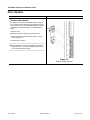
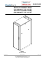
ID-00210-000
Enclosure Installation Guide
37U Cabinet (37”DP / 42”DP)
42U Cabinet (37”DP / 42”DP)
45U Cabinet (37”DP / 42”DP)
Figure 1
42U X 42” DP Shown
ID-00210-000
REV D, ECO2773
Proprietary Information of SharkRack, Inc.
32920 Alvarado-Niles Rd Suite 250, Union City, CA 94587
510-477-7900 • 510-324-1664 • www.sharkrack.com
Page 1 of 46
SharkRack Enclosure Installation Guide
Table of Contents
Table of Contents ...................................................................................................................... 2
Introduction................................................................................................................................ 3
Symbols in Text ......................................................................................................................... 4
Important Safety Notes For Installation ..................................................................................... 4
Chapter 1 Site Preparation ........................................................................................................ 6
Check Facility Provisions ................................................................................................ 6
Cabinet with Full Rear and Front Doors.......................................................................... 7
Cabinet with Split Rear Door........................................................................................... 8
Chapter 2 Receiving and Unpacking ......................................................................................... 9
Unpacking Instructions- Standard Packaging ............................................................... 10
Unpacking Instructions- Integration Packaging............................................................. 12
Chapter 3 Configure Accessories into the Cabinet .................................................................. 14
Configure Optional Accessories.................................................................................... 14
Installing and Removing Doors ..................................................................................... 15
Installing and Removing Doors (cont.) .......................................................................... 16
Door Handles ................................................................................................................ 17
How to Reverse the Door Swing ................................................................................... 18
How to Reverse the Door Swing (cont.)........................................................................ 20
Adjusting the Leveling Feet........................................................................................... 21
Installing the Retractable Tip Guard.............................................................................. 22
Installing the Floor Mounting Brackets .......................................................................... 23
Adjusting or Replacing the Mounting Rails ................................................................... 24
How to Remove or Install a Top Panel.......................................................................... 25
How to Remove or Install Side Panels.......................................................................... 26
Installing a Grounding Kit.............................................................................................. 27
Using the SharkTRAC™ and SharkSNAP™ ................................................................ 28
Installing a Typical 19 inch EIA Power Strip (cont.)....................................................... 29
Installing a Typical 19 inch EIA Power Strip (cont.)....................................................... 30
Installing a Typical 19 inch EIA Power Strip (cont.)....................................................... 31
Cable Management....................................................................................................... 32
Installing a MultiBay Kit................................................................................................. 33
Chapter 4 Install Computer Equipment.................................................................................... 34
Cabinet settings for various manufacturers’ devices..................................................... 34
Chapter 5 Final Assembly........................................................................................................ 36
Appendix A: Glossary .............................................................................................................. 37
Appendix B: Basic Cabinet Components ................................................................................. 40
Appendix C: Cabinet Specifications......................................................................................... 42
Warranty .................................................................................................................................. 46
ID-00210-000
REV D, ECO2773
Page 2 of 46
SharkRack Enclosure Installation Guide
Introduction
Thank you for buying a SharkRack computer cabinet. The SharkRack family of computer
cabinets has been designed with great care and made with the highest quality materials to
provide you with many years of satisfactory use. The SharkRack cabinet provides a top of the
line cabinet with features that make installation, management, and ongoing maintenance fast,
easy, and safe. We sincerely hope you enjoy using your SharkRack cabinet and we always
welcome your feedback. If you have technical questions about any aspect of installing or using
your computer cabinet, please call us at 87-SHARKRACK (877-427-5722).
SharkRack intends this manual to guide you through a smooth cabinet installation. SharkRack
assumes that you are qualified in the servicing of computer equipment and trained in
recognizing hazards in products with high energy levels. SharkRack also assumes you are
qualified to move heavy pieces of equipment. All the instructions here are presented in great
detail.
This document contains general installation instructions for the various SharkRack cabinet
configurations and many of the common optional devices that can be installed into a SharkRack
cabinet. Always consult the documentation that comes with your computer product or accessory
for detailed installation instructions.
The following diagram shows an overview of a common cabinet installation.
Chapter 1
Site
Preparation
Installing and Removing Doors
Changing Door Handles
Chapter 2
Receiving
And
Unpacking
How to Reverse the Door Swing
Adjusting the Leveling Feet
Installing the Retractable Tip Guard
Installing the Floor Mounting Brackets
Chapter 3
Configure
Accessories
Into the Cabinet
Adjusting or Replacing the Mounting Rails
Installing Side Mounting Brackets
How to Remove or Install a Top Panel
How to Remove or Install Side Panels
Installing a Grounding Kit
Chapter 4
Install
Computer
Equipment
Using the SharkTRAC™ and SharkSNAP™
Installing a 19 inch EIA Power Strip
Cable Management
Installing a MultiBay Kit
Chapter 5
Final
Assembly
ID-00210-000
Figure 2
Common Cabinet Installation Diagram
REV D, ECO2773
Page 3 of 46
SharkRack Enclosure Installation Guide
Symbols in Text
WARNING: Text set off in this manner indicates that failure to follow directions in the warning could
result in bodily harm or loss of life.
CAUTION: Text set off in this manner indicates that failure to follow directions could result in
damage to equipment or loss of information.
Note: Text set off in this manner presents commentary, sidelights, or interesting points of information.
Important Safety Notes For Installation
Note:
The information contained in this document is subject to change without notice.
SharkRack makes no warranty of any kind with regard to this material, including, but not limited
to, the implied warranties of merchantability and fitness for a particular purpose.
SharkRack shall not be liable for errors contained herein or for incidental or consequential
damages in connection with the furnishing, performance, or use of this material.
SharkRack assumes no responsibility for the use or reliability of the software or hardware
installed into a SharkRack cabinet.
Pictures in this manual represent a typical configuration. Your actual configuration may vary.
WARNING:
Always install a stabilizing/anti-tip device such as Floor Mounting Brackets or a Retractable Tip
Guard.
Always install the UPS (uninterruptible power supply) in the bottom of the rack.
Always install the heaviest equipment in the bottom of the rack.
Always install servers and power devices in the rack from the bottom to the top.
Do not extend more than one sliding device at a time.
The center of gravity for an extended unit cannot exceed 16 inches from the face of the cabinet.
If an extended device exceeds this distance, the configured cabinet might be unstable.
The maximum allowable weight for devices on slides is dependant upon the specific slide. Do
not install sliding devices exceeding maximum allowed weight.
ID-00210-000
REV D, ECO2773
Page 4 of 46
SharkRack Enclosure Installation Guide
WARNING (CONT.):
Plug cabinet power cords into electrical outlets that are located near the cabinet and are easily
accessible.
Connect all devices installed in a rack to power devices installed in the same cabinet. Do not
plug into a power device installed in a different cabinet.
Check the equipment power rating before plugging into a cabinet power device. Check that both
the voltage range and current draw are within the limitations of the power device. The voltages
of the power device receptacles are typically equal to the voltages of the UPS or AC source.
To avoid overloading, check the total input current rating of the equipment being connected to a
power device to ensure that it does not exceed the maximum rating of the power strip or any
UPS to which it may be connected.
Each installed server or other device might have more than one power cord. Be sure to
disconnect all power cords in the cabinet before servicing any device in the cabinet.
CAUTION:
Removing components from the top portion of the rack improves cabinet stability during
relocation. Follow these general guidelines whenever you relocate a populated cabinet within a
room or building:
Reduce the weight of the rack by removing equipment starting at the top of the rack. When
possible, restore the cabinet to the configuration as you received it. If this is not possible or the
configuration is unknown, remove all devices in the 11U position and above before moving the
cabinet.
Inspect the route that you plan to take and eliminate any potential hazards.
Verify that the route that you choose to move the rack cabinet can support the weight of the
loaded rack cabinet, which may exceed 2500 lbs.
Verify that all doorways can accommodate the cabinet.
Ensure that all devices, drawers, doors, and cables are secure.
Ensure that all leveling feet are raised to their highest position.
Ensure that the floor mounting brackets are removed (see Figure 6).
Once the cabinet is in its new location, repopulate the cabinet from the lowest position to the
highest position.
If long distance relocation is required, pack the cabinet in the original packaging material, or
equivalent. Also, use the floor mounting brackets to bolt the cabinet to the pallet.
ID-00210-000
REV D, ECO2773
Page 5 of 46
SharkRack Enclosure Installation Guide
Chapter 1 Site Preparation
Check Facility Provisions
Ensure that the following conditions are met:
ID-00210-000
•
Floor is level and of sufficient strength to support the rack and your equipment. At
maximum gross weight, the floor must be able to support 1000 lb/in2.
•
A qualified professional should complete site electrical power supply set-up. Ensure the
types of outlets are consistent with the type of plugs on the power devices to be used.
•
Check with a qualified HVAC technician to make sure the environment will support the
heat load of the products being installed in the cabinet.
•
Select a location for the cabinet that will allow adequate space for the door to open freely
and slide-mounted equipment to be extended.
•
Check that the site can accommodate the cabinet footprint and mounting locations
according to the illustrations in Figure 3 and Figure 4.
REV D, ECO2773
Page 6 of 46
SharkRack Enclosure Installation Guide
Rack Cabinet Footprint and Mounting Locations for:
Cabinet with Full Rear and Front Doors
Rear Door
Front Door
Figure 3
42U X 37DP (TOP VIEW) and 42U X 42DP (BOTTOM VIEW) Shown
Table 1
Cabinet Dimensions
DIM
37” CABINET
42” CABINET
45” CABINET
A
86”
91”
82”
B
41”
46”
49”
C
37”
42”
45”
D
35”
40”
43”
38” or 40”
43” or 45”
46” or 48”
Leveling Feet
E
Floor mounting brackets
ID-00210-000
REV D, ECO2773
Page 7 of 46
SharkRack Enclosure Installation Guide
Rack Cabinet Footprint and Mounting Locations for:
Cabinet with Split Rear Door
Rear Doors
Front Door
Figure 4
42U X 37DP (TOP VIEW) and 42U X 42DP (BOTTOM VIEW) Shown
Table 2
Cabinet Dimensions
DIM
37” CABINET
42” CABINET
45” CABINET
A
74”
79”
82”
B
41”
46”
49”
C
37”
42”
45”
D
35”
40”
43”
38” or 40”
43” or 45”
46” or 48”
Leveling Feet
E
Floor mounting brackets
ID-00210-000
REV D, ECO2773
Page 8 of 46
SharkRack Enclosure Installation Guide
Chapter 2 Receiving and Unpacking
Check package and receiving area
•
Verify contents and condition.
•
Move the packaged cabinet on its pallet as close to its final destination as possible.
•
Be sure there is enough room to unload the cabinet from its packaging. In front of the
pallet, it requires at least 7 feet for standard packaging (with or without pallet) and 13
feet for integration (crate) packaging to unload the cabinet.
•
Many SharkRack cabinets come on casters, which allow the cabinet to be rolled to its
destination after unpacking.
Note:
Ensure clear passage from the receiving site to the uncrating site.
Do not lift an unpackaged cabinet with a forklift.
Do not move the packaged cabinet without adequate assistance.
Be sure leveling feet are raised before rolling to prevent tipping or damage to the feet.
ID-00210-000
REV D, ECO2773
Page 9 of 46
SharkRack Enclosure Installation Guide
Unpacking Instructions- Standard Packaging
Step
Detail
Note: Unpacking of a cabinet requires at least two
people.
There must be at least 7 feet of clear area in front of the
loaded pallet to unload the cabinet.
1. Unwrap packaging material from around the cabinet
Figure 5
42U X 42in DP Shown
2. Remove the (4) bolts securing the front Floor
Mounting Bracket to the pallet and cabinet.
3. Repeat Step 2 for the rear Floor Mounting Bracket
Figure 6
42U X 42in DP Shown
Removal of Floor Mounting Bracket.
ID-00210-000
REV D, ECO2773
Page 10 of 46
SharkRack Enclosure Installation Guide
Step
Detail
CAUTION: Be sure the leveling feet are fully
raised to prevent accidental tipping.
Figure 7
View of Caster and Leveling Foot
4. With one person on each side of the enclosure,
carefully roll it toward the rear of the pallet until the
rear casters clear the back edge of the pallet.
Continue to slide the enclosure rearward until the
rear casters make contact with the floor.
5. While one person carefully tips the enclosure slightly
away from the pallet, have the other person pull the
pallet away from the enclosure.
(Optional) Store all packing materials in a safe place
for future use.
Figure 8
42U X 42DP Shown
ID-00210-000
REV D, ECO2773
Page 11 of 46
SharkRack Enclosure Installation Guide
Unpacking Instructions- Integration Packaging
Step
Detail
WARNING: A fully loaded cabinet is very
heavy. Take proper precautions when moving
the cabinet
Note: Unpacking of a cabinet requires at least two
people.
There must be at least 13 feet of clear area in front of
the loaded crate to unload the cabinet.
1. Open the Crate. Loosen the (6) clips securing the
front of the crate. The front of the crate is used as a
ramp to unload the cabinet.
Figure 9
Shipping Crate Shown for 42U X 37DP Cabinet
2. Position the loading ramp onto the front of the crate.
3. Remove the (2) wing nuts securing the piece of wood
at the base of the cabinet.
#3
4. Remove the (4) bolts securing the front Floor
Mounting Bracket to the crate and cabinet.
#4
Figure 10
Shipping Crate with 42U X 37DP Cabinet Shown
ID-00210-000
REV D, ECO2773
Page 12 of 46
SharkRack Enclosure Installation Guide
Unpacking Instructions- Integration Packaging (cont.)
Step
Detail
CAUTION: Be sure the leveling feet are fully
raised to prevent accidental tipping.
(See Figure 7 for details.)
5. With one person on each side of the enclosure,
carefully roll it out of the wooden crate.
6. Unwrap packing material from around the cabinet.
(Optional) Store all packing materials in a safe place
for future use.
Figure 11
Shipping Crate with 42U X 37DP Cabinet Shown
ID-00210-000
REV D, ECO2773
Page 13 of 46
SharkRack Enclosure Installation Guide
Chapter 3 Configure Accessories into the Cabinet
Configure Optional Accessories
The SharkRack cabinet can be configured using multiple optional accessories. The
configuration depends on your specific application and may vary from cabinet to cabinet. The
following list of processes is organized to help guide you through the typical steps of configuring
optional accessories. Since each configuration is different, some processes may be excluded.
Also, some processes will refer back to previous processes.
•
Installing and Removing Doors
•
Changing Door Handles
•
How to Reverse the Door Swing
•
Adjusting the Leveling Feet
•
Installing the Retractable Tip Guard
•
Installing the Floor Mounting Brackets
•
Adjusting or Replacing the Mounting Rails
•
Installing Side Mounting Brackets
•
How to Remove or Install a Top Panel
•
How to Remove or Install Side Panels
•
Installing a Grounding Kit
•
Using the SharkTRAC™ and SharkSNAP™
•
Installing a 19 inch EIA Power Strip
•
Cable Management
•
Installing a MultiBay Kit
Tools Required for Cabinet setup:
ID-00210-000
•
#2 Phillips Screwdriver
•
1/2” – 9/16” Open End Wrench (Included with leveling foot kit)
•
9/16” Hex Socket and Ratchet with 3” Extension Bar (Optional)
•
Straight Blade Screwdriver (Optional for adjusting the leveling feet)
REV D, ECO2773
Page 14 of 46
SharkRack Enclosure Installation Guide
Installing and Removing Doors
Step
Detail
To remove doors:
1. Open the door.
2. Pull down on the springloaded hinge pin
attached to the top of
the door.
#3
3. Move top of door away
from enclosure and lift
the bottom of door up
from the cabinet and set
aside.
#2
Figure 12
42U X 37DP Shown
ID-00210-000
REV D, ECO2773
Page 15 of 46
SharkRack Enclosure Installation Guide
Installing and Removing Doors (cont.)
Step
Detail
To install doors:
1. Align the lower door hinge pin with the hole in
the bottom hinge bracket and slide the hinge pin
into the hole.
2. Pull down the upper hinge pin.
3. Align the upper hinge pin with the hole in the
upper hinge bracket and release the hinge pin
into the hole.
4. Make sure the door opens and closes properly.
CAUTION: Ensure that hinge pins are
secured into the hinge brackets. If not
properly installed the door may
unexpectedly fall.
Figure 13
42U X 37DP Shown
ID-00210-000
REV D, ECO2773
Page 16 of 46
SharkRack Enclosure Installation Guide
Door Handles
Step
Detail
Remove door handle:
To enhance your cabinet, SharkRack offers an optional
line of electronic door handles which use HID or keypad
entry. These locks can be networked together for remote
management and access tracking. To install follow the
steps.
CAM
1. Open the door.
2. Rotate the handle to align the cam pointing down.
3. Use a screwdriver to push the snaps inward. Lift the
handle off the door.
4. Install new door handle.
Note: The installation of some door handles may require
additional steps. Consult the installation guide with for
your specific door handle option.
Figure 14
Snap-In Handle and Lock
ID-00210-000
REV D, ECO2773
Page 17 of 46
SharkRack Enclosure Installation Guide
How to Reverse the Door Swing
Step
Detail
Reverse the door handle:
1. Open the door.
2. Rotate the handle to align the cam pointing
down.
3. Use a screwdriver to push the snaps inward. Lift
the handle off the door.
CAM
4. Remove the cam screw securing the cam and
rotate the cam 180°. Re-secure with the cam
screw.
5. Rotate the door handle assembly 180° and
reinstall it.
Figure 15
Snap-In Handle and Lock
ID-00210-000
REV D, ECO2773
Page 18 of 46
SharkRack Enclosure Installation Guide
Step
Detail
Reverse the door hinge brackets:
4. Remove the door. (See “Installing and
Removing Doors” on page 15)
5. Use a Phillips head screwdriver to remove the
hinge pin brackets and latch bracket(s) from the
cabinet frame.
Figure 16
42U X 37DP Shown
ID-00210-000
REV D, ECO2773
Page 19 of 46
SharkRack Enclosure Installation Guide
How to Reverse the Door Swing (cont.)
Step
Detail
6. Reinstall the hinge pin brackets and latch bracket(s) on
the opposite side of the cabinet.
7. Reinstall the door.
CAUTION: Ensure that the door and its hinge
pins are secured into the hinge brackets after the
door is reinstalled.
Figure 17
42U X 37DP Shown
ID-00210-000
REV D, ECO2773
Page 20 of 46
SharkRack Enclosure Installation Guide
Adjusting the Leveling Feet
Step
Detail
The leveling feet help stabilize the cabinet and
keep the cabinet level on uneven floors. This
should be done before you install products into
the cabinet.
1.
Locate the (4) leveling feet. There is one
in each corner as shown.
2.
Loosen the Jam Nut.
Figure 18
42U X 37DP Shown
3. Lower the leveling feet. Rotate the leveling
feet clockwise from inside the cabinet using
a straight blade screwdriver or from
underneath the cabinet using the supplied
9/16” wrench. The levelers should plant
firmly to the floor.
Figure 19
42U X 37DP Shown
ID-00210-000
REV D, ECO2773
Page 21 of 46
SharkRack Enclosure Installation Guide
Installing the Retractable Tip Guard
Step
Detail
The Retractable Tip Guard should be used when the
cabinet is not secured to the floor and equipment is being
slid in and out of the cabinet. This feature is used to
prevent the cabinet from tipping over.
1. Insert the legs of the tip guard into the base of the
cabinet. Detent the spring latches towards the rear of
each leg.
Figure 20
42U X 37DP Shown
2. Check the operation of the Retractable Tip Guard. It
should freely cycle through its full range of motion.
Note: Some adjustment of the center section may be
required for smooth operation. To adjust loosen the (4)
screws at the front of the Tip Guard. Reposition the
pieces as required. Tighten the screws.
Note: When in use, remember to fully lower both leveling
feet on the retractable stabilizer kit until they are firmly
planted on the floor.
Figure 21
42U X 37DP Shown
ID-00210-000
REV D, ECO2773
Page 22 of 46
SharkRack Enclosure Installation Guide
Installing the Floor Mounting Brackets
Step
Detail
The Floor Mounting Brackets should be used
when sliding equipment in and out of the
cabinet and no other stabilizing provisions are
in place. This safety feature is used to prevent
the cabinet from tipping over or to keep it in a
fixed location. Consult a contractor or trained
professional on the best method of fastening
your cabinet to the floor.
1. Prepare the location. Check the location to
make sure the area is suitable to bolt down
the cabinet. (Refer to Site Preparation
Information).
Figure 22
Floor Mounting Bracket
2. Secure the Floor Mounting Brackets to the
front and rear of the cabinet base using
supplied hardware.
3. Have a qualified professional fasten the
brackets to your data center floor.
OR
Figure 23
Floor Mounting Bracket on 42U X 37DP cabinet
ID-00210-000
REV D, ECO2773
Page 23 of 46
SharkRack Enclosure Installation Guide
Adjusting or Replacing the Mounting Rails
Step
Detail
Adjusting the mounting rails:
The mounting rails are factory set at 29.12 inches
apart. However, both the front and rear mounting
rails are adjustable to any depth within the
cabinet.
1. Loosen the screws securing each mounting
rail using a Phillips screwdriver.
2. Adjust the mounting rail to the desired location.
Make sure each mounting rail is adjusted
parallel and square inside the cabinet.
3. Tighten the screws.
4. Repeat steps for any other rail to be adjusted.
Replacing the mounting rails:
To replace any of the mounting rails you must:
1. Loosen the screws securing the mounting rail.
CAUTION: Remove bottom screws
first to help eliminate the possibility of
the rail falling on your head.
2. Remove the rail and replace with another style
rail available from SharkRack.
3. Secure the mounting rail with the screws that
were previously removed.
ID-00210-000
Figure 24
Section view of 42U X 37DP Cabinet
REV D, ECO2773
Page 24 of 46
SharkRack Enclosure Installation Guide
How to Remove or Install a Top Panel
Step
Detail
The Top Panel can be removed.
To remove a Top Panel:
1. Unlock the Top Panel using the key.
2. With the key turned in the unlocked position, lift up until
you can grab the top panel with your free hand.
Note: If using a grounding kit, remove the cable prior to
lifting the panel from the Cabinet Frame. See “Installing
a Grounding Kit” for details.
3. Remove the Top Panel and set aside.
To install a Top Panel:
1. Set the Top Panel on the top of the Cabinet Frame. When
installed properly it should sit flush with the rest of the
cabinet
2. Lock the Top Panel using the key, if preferred.
Figure 25
42U X 37DP Cabinet Shown
ID-00210-000
REV D, ECO2773
Page 25 of 46
SharkRack Enclosure Installation Guide
How to Remove or Install Side Panels
Step
Detail
The Side Panels can be removed to provide
further access to equipment mounted inside
the cabinet. This is a great way to get added
access for cable management or installing
powerstrips.
To remove a Side Panel:
1. Unlock the Side Panel using the key, if
necessary.
2. Slide both Side Panel latches inward
towards each other at the same time and
tilt the panel outward.
Note: If using a grounding kit, remove the
cable prior to lifting the panel from the
Cabinet Frame. See “Installing a
Grounding Kit” for details.
3. Release the latches and lift the Side Panel
up and off the cabinet frame.
4. Remove the Side Panel and set aside.
To install a Side Panel:
1. Approaching the cabinet from the side, set
the bottom edge of the Side Panel onto
the Cabinet Frame
2. The bottom edge of the panel must
securely engage with the cabinet frame
before pushing the top of the panel
forward into place.
3. Lock the panel using the key, if preferred.
Figure 26
42U X 37DP Cabinet Shown
ID-00210-000
REV D, ECO2773
Page 26 of 46
SharkRack Enclosure Installation Guide
Installing a Grounding Kit
Step
Detail
Grounding points are provided on the various cabinet
components so that each component can be electrically
bonded to the frame.
Detail A:
Shows how to route the grounding cables through the
frame of the cabinet. Connection (1) attaches to either of
the door assemblies. Connection (2) attaches to the side
panel
Detail B:
Shows where connection (2) attaches to the corner of the
Side Panel
Detail C:
Shows how to route the grounding cable to the top panel.
Detail D:
Shows the door grounding cable being routed through the
face of the corner post (reverse side of Detail A).
Figure 27
Grounding Points
42U X 37DP Cabinet Shown
ID-00210-000
REV D, ECO2773
Page 27 of 46
SharkRack Enclosure Installation Guide
Using the SharkTRAC™ and SharkSNAP™
Step
Detail
The SharkTRAC™ is a patent pending platform
consisting of a series of holes, which allows attachment
of various devices.
SharkSNAP™
We have also developed a family of SharkSNAP™ tool–
less clip-in devices that attach directly to the
SharkTRAC™. SharkSNAP™ devices reduce time and
hassle when installing things such as power strips, patch
panels, routers, and environmental monitoring products.
SharkTRAC™
Figure 28
1. To install a SharkSNAP™, align the small metal
fingers over the holes of the SharkTRAC™. Drop the
fingers through the holes and slide the SharkSNAP™
into the track until the retention pin snaps into place.
2. To remove a SharkSNAP™, pull up on the retention
pin and slide the SharkSNAP™ back and away from the
SharkTRAC™.
Figure 29
ID-00210-000
REV D, ECO2773
Page 28 of 46
SharkRack Enclosure Installation Guide
Installing a Typical 19 inch EIA Power Strip
Step
Detail
1. Secure to the Cabinet Mounting Rails
1a. (As required) Install 10-32 cage nuts. Some mounting
rails require the use of cage nuts; install them into the
appropriate holes as shown.
Or
Or
Install 10-32 clip nuts as shown. Some mounting rails
require the use of clip nuts; install them into the
appropriate holes as shown.
Figure 30
1b. (As required) Adjust the mounting brackets orientation.
Remove the hardware from the brackets as required.
Rotate the mounting brackets as required. Reinstall the
hardware.
Figure 31
1c. Secure the strip using (6) 10-32 x 1/2 inch panhead
screws.
1d. Connect necessary cables.
Figure 32
ID-00210-000
REV D, ECO2773
Page 29 of 46
SharkRack Enclosure Installation Guide
Installing a Typical 19 inch EIA Power Strip (cont.)
Step
Detail
2. Secure to the SharkTRAC™ using
SharkSNAP™ Brackets
Note: There must be two SharkSNAP™ brackets installed
which allows a power strip to clip in-between them.
2a. Install a pair of SharkSNAP™ brackets into the
SharkTRAC™. See “Using the SharkTRAC™ and
SharkSNAP™ on page 28 for further details.
2b. Approach the SharkSNAP™ brackets with the power
strip. Align the pins of the SharkSNAP™ bracket with
the screw holes on the strip mounting brackets and push
the strip straight onto the bracket. There is a spring that
holds the strip into place.
2c. Connect necessary cables.
Figure 33
ID-00210-000
REV D, ECO2773
Page 30 of 46
SharkRack Enclosure Installation Guide
Installing a Typical 19 inch EIA Power Strip (cont.)
Step
Detail
3. Secure to the SharkTRAC™ using screws
3a. Install 10-32 cage nuts. The SharkTRAC™ requires the
use of cage nuts; install them into the appropriate holes
using the method shown.
Figure 34
Cage Nut instillation
3b. (As required) Adjust the mounting brackets orientation.
Remove the hardware from the brackets as required.
Rotate the mounting brackets as required. Reinstall the
hardware.
Figure 35
Mounting Bracket
3c. Secure the strip using (6) 10-32 x 1/2 inch panhead
screws.
3d. Connect necessary cables.
Figure 36
PDU installation
ID-00210-000
REV D, ECO2773
Page 31 of 46
SharkRack Enclosure Installation Guide
Cable Management
Step
Detail
The SharkRack cabinet has been designed with
integrated cable management. There are
numerous provisions for running cables in the
corner posts of the frame as well as out the top,
bottom, in both the front and back of the cabinet.
There are also many places that cables can be tied
down to the frame by using nylon ties or hook and
loop strips or ties.
Figure 37
Cable Management
ID-00210-000
REV D, ECO2773
Page 32 of 46
SharkRack Enclosure Installation Guide
Installing a MultiBay Kit
Step
Detail
MultiBay kits are used to group two or more
SharkRack cabinets together. MultiBay kits can
be installed prior to installing computer
equipment into the rack cabinet or after
equipment is already loaded.
(Optional) Remove the two side panels facing
each other from the two cabinets being bayed
together. See “How to Remove or Install Side
Panels” on page 26.
1. Move the two cabinets together.
2. As necessary, adjust the leveling feet until the
cabinets are level and square to each other.
3. Secure the (4) MultiBay plates to the cabinets
using (4) M6 screws in each plate
Figure 38
MultiBay Kit
ID-00210-000
REV D, ECO2773
Page 33 of 46
SharkRack Enclosure Installation Guide
Chapter 4 Install Computer Equipment
To install computer equipment into the cabinet:
•
Plan component locations in the cabinet.
•
Install computer equipment.
•
Route and secure all loose cables accordingly.
Note: Refer to important safety note for installation on page 4 prior to installing equipment.
Cabinet settings for various manufacturers’ devices
Note: Always review equipment manufacturer’s manual for specific mounting specifications.
Compaq™
•
Most Compaq rack mountable products require 3/8” square-holed “L”-style mounting
rails.
•
Distance between the front and rear mounting rails needs to be 29.12 inches. Many rack
mount kits from Compaq use fixed depth side rails and require the cabinet mounting rails
to be exactly 29.12 inches apart.
•
Typically products use 6mm cage nuts and screws.
Dell™
•
Most Dell rack mountable products require 3/8” square-holed “L”-style mounting rails.
•
Typically products use 10-32 cage nuts and screws.
•
If a front door is required, use a fully vented front door.
HP™
ID-00210-000
•
Most HP rack mountable products use a 3/8” square-holed “L”-style mounting rails.
•
Typically products use 10-32 cage nuts and screws, but some use M5 fasteners.
•
If a front door is required, use a fully vented front door.
•
If a front door is required, you may need to set all mounting rails back.
REV D, ECO2773
Page 34 of 46
SharkRack Enclosure Installation Guide
Cabinet settings for various manufacturers’ devices (cont.)
IBM™
•
Most IBM rack mountable products use a 3/8” square-holed “L”-style mounting rails.
•
Typically products use 10-32 cage nuts and screws.
•
If a front door is required, use a fully vented front door.
•
If a front door is required, you may need to set all mounting rails back.
Sun™
ID-00210-000
•
Sun has not published a corporate wide set of racking requirements for 3rd party
cabinets.
•
Check with a SharkRack Representative or www.sharkrack.com for recommended
racking hardware.
•
Most equipment works with the use of SharkRack’s 3/8” square-holed L-style mounting
rails.
•
Many of Sun rack mount kits use 10-32 cage nuts and screws, but some of their newer
equipment uses M6 hardware.
REV D, ECO2773
Page 35 of 46
SharkRack Enclosure Installation Guide
Chapter 5 Final Assembly
Check for Functionality
ID-00210-000
•
Have a qualified electrician verify the power sources for your specified power
requirements.
•
Check that there is no obstruction to any device that needs to be accessed for
maintenance.
•
Check that there is easy access to the power strips
•
Check that all fasteners are tight. Typical torque values are:
o
10-32
30 inch-lbs.
o
M5
24 inch-lbs.
o
M6
40 inch-lbs.
•
Re-install the doors (See “Installing and Removing Doors” for details).
•
Power up devices.
REV D, ECO2773
Page 36 of 46
SharkRack Enclosure Installation Guide
Appendix A: Glossary
EIA:
For more than 72 years the Electronic Industries Alliance has been the national trade
organization representing U.S. electronics manufacturers. Committed to the competitiveness of
the American producer, EIA represents the entire spectrum of companies involved in the design
and manufacture of electronic components, parts, systems and equipment for communications,
industrial, government and consumer uses.
U (or RU):
A Rack Unit, or sometimes referred to as “U”, is the measure of space in a rack cabinet
enclosure equal to 1.75 inches as defined by the EIA-310 standard. Each Rack Unit in an EIA
rack cabinet enclosure will have three holes. The first hole is spaced at .25 inches from the
bottom of the U to the center, followed by 2 holes spaced at .625 center to center and then .25
inches to the top of the RU.
Figure 39
“U” Spacing
Zero U:
Zero U is any rack unit that is not a part of the main stacked rack unit in a cabinet.
ID-00210-000
REV D, ECO2773
Page 37 of 46
SharkRack Enclosure Installation Guide
Appendix A: Glossary (cont.)
Cage Nut:
A fastener typically used in square-hole universal type racks, similar to a Clip Nut. When
selecting the correct cage nut you must specify the thread size as well as the thickness of the
mounting rail they will be attaching to.
Figure 40
Cage Nut
Clip Nut:
A fastener typically used on round-hole universal type racks, similar to a Cage Nut. They come
in different shapes and sizes. You must specify the thread type as well as the thickness of the
mounting rail they will be attaching to.
Figure 41
Clip Nut
SharkSNAP™:
SharkSNAP™ is a family of tool–less clip-in devices that attach to the SharkTRAC™.
SharkSNAP™ devices reduce time and hassle when installing things such as power strips,
patch panels, routers, and environmental monitoring products into a cabinet.
Figure 42
SharkSNAP™
ID-00210-000
REV D, ECO2773
Page 38 of 46
SharkRack Enclosure Installation Guide
Appendix A: Glossary (cont.)
SharkTRAC™:
The SharkTRAC™ is a platform consisting of a series of holes, which allows attachment of
various devices such as the family of SharkSNAP™ tool-less clip-in devices.
Figure 43
SharkTRAC™
ID-00210-000
REV D, ECO2773
Page 39 of 46
SharkRack Enclosure Installation Guide
Appendix B: Basic Cabinet Components
Note: Before you begin configuring your SharkRack cabinet, it is best to verify that you have received all
necessary items to begin your installation. Also verify that your equipment has arrived free of damage. Rack
configurations may vary.
Figure 44
42U X 42DP Cabinet – Exploded View
ID-00210-000
REV D, ECO2773
Page 40 of 46
SharkRack Enclosure Installation Guide
Parts List
REF
Description
Quantity/REF
A
B
1
E
F
G
I
J
H
Cabinet Frame
Front Door Kit
Grommet Bumper
Bracket, Latch – Front Door
Front Hinge, Bracket Top-Left/Bottom-Right
Front Hinge, Bracket Top-Right/Bottom-Left
Front Door Perforated
Snap-In swing Handle
#10-32X.375 Flat Head Screw
Full Rear Door Kit
Bracket, Latch, Full Rear Door
Snap-In swing Handle
Grommet Bumper
Rear Hinge, Bracket Top-Left/Bottom-Right
Rear Hinge, Bracket Top-Right/Bottom-Left
#10-32X.375 Flat Head Screw
Full Rear Door Perforated
Split Rear Door Kit
Rod Latch
#10-32 Flat Head Screw
#10 Hex Nut w/Tooth Washer
Rear Hinge, Bracket Top-Left/Bottom-Right
Rear Hinge, Bracket Top-Right/Bottom-Left
Grommet Bumper
Right Hand Split Door
Left Hand Split Door
5” Filler Panel
Side Panel
Casters
Leveling Feet
Floor Mounting Bracket
Non-Perforated Top Panel
I
Mounting Rails (Set of 4)
C
D
2
1
1
1
1
1
8
1
1
2
1
1
8
1
1
16
2
2
2
7
1
1
2
2
4
4
2
1
1
Table 1
Parts List
ID-00210-000
REV D, ECO2773
Page 41 of 46
SharkRack Enclosure Installation Guide
Appendix C: Cabinet Specifications
Note: The information listed on the chart in Table 2 is taken from SharkRack’s latest generation of
racks. Previous generations vary from that listed bellow.
Note: The Reference column of Table 2 references the Figures and the following pages. All
Measurements are listed in Inches unless otherwise specified.
Table 2
Cabinet Specifications
All dimensions are nominal unless indicated otherwise
ID-00210-000
REV D, ECO2773
Page 42 of 46
SharkRack Enclosure Installation Guide
Cabinet Dimensions (Top View)
Figure 45
Cabinet Dimensions
ID-00210-000
REV D, ECO2773
Page 43 of 46
SharkRack Enclosure Installation Guide
Mounting Rail Dimensions (Front View)
Figure 46
Mounting Rails
ID-00210-000
REV D, ECO2773
Page 44 of 46
SharkRack Enclosure Installation Guide
Figure 1...................................................................................................................................................................... 1
Figure 3...................................................................................................................................................................... 7
Figure 4...................................................................................................................................................................... 8
Figure 5.................................................................................................................................................................... 10
Figure 6.................................................................................................................................................................... 10
Figure 7.................................................................................................................................................................... 11
Figure 8.................................................................................................................................................................... 11
Figure 9.................................................................................................................................................................... 12
Figure 10.................................................................................................................................................................. 12
Figure 11.................................................................................................................................................................. 13
Figure 12.................................................................................................................................................................. 15
Figure 13.................................................................................................................................................................. 16
Figure 14.................................................................................................................................................................. 17
Figure 15.................................................................................................................................................................. 18
Figure 16.................................................................................................................................................................. 19
Figure 17.................................................................................................................................................................. 20
Figure 18.................................................................................................................................................................. 21
Figure 19.................................................................................................................................................................. 21
Figure 20.................................................................................................................................................................. 22
Figure 21.................................................................................................................................................................. 22
Figure 22.................................................................................................................................................................. 23
Figure 23.................................................................................................................................................................. 23
Figure 24.................................................................................................................................................................. 24
Figure 25.................................................................................................................................................................. 25
Figure 26.................................................................................................................................................................. 26
Figure 27.................................................................................................................................................................. 27
Figure 28.................................................................................................................................................................. 28
Figure 30.................................................................................................................................................................. 29
Figure 31.................................................................................................................................................................. 29
Figure 32.................................................................................................................................................................. 29
Figure 33.................................................................................................................................................................. 30
Figure 34.................................................................................................................................................................. 31
Figure 35.................................................................................................................................................................. 31
Figure 36.................................................................................................................................................................. 31
Figure 37.................................................................................................................................................................. 32
Figure 38.................................................................................................................................................................. 33
Figure 39.................................................................................................................................................................. 37
Figure 40.................................................................................................................................................................. 38
Figure 41.................................................................................................................................................................. 38
Figure 42.................................................................................................................................................................. 38
Figure 43.................................................................................................................................................................. 39
Figure 44.................................................................................................................................................................. 40
Figure 45.................................................................................................................................................................. 43
Figure 46.................................................................................................................................................................. 44
ID-00210-000
REV D, ECO2773
Page 45 of 46
SharkRack Enclosure Installation Guide
Warranty
LIMITED WARRANTY AND WARRANTY DISCLAIMER - Seller warrants that the System will be free from defects
in materials and workmanship for a period of one (1) year from date of delivery to customer premises. Seller’s
sole liability and Customer’s sole and exclusive remedy for any breach of this warranty is, at Seller’s option and
expense, to repair or replace any defective System that is returned to it by Customer. Seller will have no
obligation under this section to the extent any defect in the System is caused by or is attributable to negligence,
accident, misuse, abuse, use of the System than in accordance with Seller’s documentation or user manual,
modifications, alterations or repairs to the System made by a party other than Seller, or actions of third parties or
like events outside Seller’s reasonable control. EXCEPT AS EXPRESSLY SET FORTH IN THIS SECTION, TO
THE EXTENT PERMITTED BY APPLICABLE LAW, SELLER DISCLAIMS ANY AND ALL OTHER
WARRANTIES, WHETHER EXPRESS, IMPLIED, OR STATUTORY, INCLUDING, WITHOUT LIMITATION, ANY
IMPLIED WARRANTIES OF MERCHANTABILITY, FITNESS FOR A PARTICULAR PURPOSE, QUALITY, OR
NONINFRINGEMENT, AND ANY WARRANTIES ARISING FROM COURSE OF DEALING OR USAGE OF
TRADE.
LIMITATIONS OF LIABILITY - IN NO EVENT WILL SELLER BE LIABLE FOR ANY SPECIAL, INCIDENTAL OR
CONSEQUENTIAL DAMAGES (INCLUDING, BUT NOT LIMITED TO, LOST PROFITS OR REVENUE, LOSS OF
USE, LOST BUSINESS OPPORTUNITIES OR LOSS OF GOODWILL), OR FOR THE COSTS OF PROCURING
SUBSTITUTE PRODUCTS, ARISING OUT OF OR IN CONNECTION WITH THESE TERMS OF SALE OR THE
USE OF THE SYSTEM, WHETHER SUCH LIABILITY ARISES FROM ANY CLAIM BASED UPON CONTRACT,
WARRANTY, TORT (INCLUDING NEGLIGENCE), PRODUCT LIABILITY OR OTHERWISE, WHETHER OR
NOT SELLER HAS BEEN ADVISED OF THE POSSIBILITY OF SUCH LOSS OR DAMAGE. IN NO EVENT
WILL SELLER’S TOTAL CUMULATIVE LIABILITY, FROM ALL CAUSES OF ACTION AND ALL THEORIES OF
LIABILITY, EXCEED THE TOTAL AMOUNTS ACTUALLY PAID TO SELLER BY CUSTOMER UNDER THE
ORDER THAT GIVES RISE TO ANY LIABILITY HEREUNDER.
During the warranty period, purchaser must promptly call SharkRack (877-427-5722) to log any such defects in
materials and workmanship.
ID-00210-000
REV D, ECO2773
Page 46 of 46