1
NETZGERÄT MZN 16 X
POWER SUPPL Y MZN 16 X
ALIMENTATIONSECTEUR
MZN 16 X
~
~
3
020
1
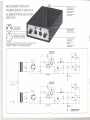
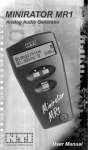
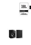
Ground connector
on rear panel
Douille de terre sur
la face arriere
Ausgangsstecker
Output connector
Fiche de sortle
1
3
Erdbuchse an der
Geräterückwand
Betriebsanzeige
Function indicator
Indicateur de service
Eingangsbuchse für Mikrofon
Input socket for microphone
Prise d'entree pour microphone
Der zweite Kanal
ist identisch
~'I
Second channel
identical
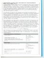
Beschaltung von außen auf die Buchsen gesehen - Siehe technische Daten
Pinconnections seen Irom top 01connector See technical data
Brochage, vu de I'exterieur - voir caracteristiques techniques
-
Le deuxieme canal
est identique
BD 138-10
BD 378-10
511
C5
C 13
100 ~/3
D3
Gay 47
GII
Tr 1
8 BOG
BOO
I{I
C7
CI
0.22
~i /100
C3
R3
47 k
4 70 ~/63
DI
470~116
ZPD 9.1
BC 416 B
C9
I
BD 138-10
90
50
2B5 V
60 Hz
C6
5t2
BD 378-10
100 ~/3
0.22 ~1100
J
.~
C 14
GI2
8BOGBOO
ca
C2
0.22 ~ I /100
)---11.
C4
D2
Tr2
470 ~/16
ZPD 9,1
470 ~/63
BC 416 B
KDntaktanordnung
nach DIN 41524
--
--
-L..
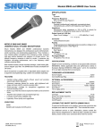
Power supply for condenser
MKH 110-1
Netzgerät für Konden8~tormlkrofone
MKH 110 und MKH 110-1
Das Netzgerät MZN 16 X dient zum Betrieb von zwei KondensatorMikrofonen MKH 110 oder MKH 110-1. Das äußerst robuste Ganz-
ist schutzisoliert.
Die Betriebsbereitschaft
wird durch je eine Leuchtdiode in jedem
Stromversorgungskanal
angezeigt. Die Leuchtintensität wächst mit
dem Betriebsstrom des angeschlossenen Mikrofons. Die beiden
Stromversorgungskanäle
sind dauerkurzschlußfest und haben eine
Strombegrenzung
auf ca. 18 mA. Beide Kanäle sind galvanisch
erdfrei. Die Adern der angeschlossenen Leitungen dürfen ein Potential von max. 100 V Gleichspannung gegen die Abschirmung aufweisen.
Each powering channel is fitted with an indicator light (LED). The
intensity of the light depends on the current of the corresponding
microphone circuit. The DC-output of the two Ieeding channels is
permanently short-circuit protected. The output current is limited to
appx. 18 mA. Both channels are groundfree. The leads 01 the cables
connected may carry a potential of up to 100 V DC-voltage with
reference to screen.
Im Interesse möglichst geringer Dämpfung der tiefen Frequenzen
bei der weiteren Übertragung der vom Mikrofon gelieferten Signale,
ist der NF-Ausgang am Stift 1 des Anschlußsteckers ohne galvanische
Trennung herausgeführt. Er führt deshalb eine Gleichspannung
gegenüber dem Stift 2, den erdfreien Schaltungsnullpunkt. Ein
Verstärker kann über einen ausreichend großen Kondensator angeschlossen werden. Die Kapazität dieses Kondensators bei gegebener Eingangsimpedanz
r des nachgeschalteten Verstärkers errechnet
sich für einen zulässigen Abfall von 1 dB bei der unteren Grenzfrequenz
fg nach der Formel
1T (r
vorhanden
Eine
-
entsprechende
am Eingang
+
. . . . . . . . ..
C =
.
Leerlauf-Ausgangsgleichspannung
..
Max. zulässiger Betriebs-Ausgangsgleichstrom
je Kanal. . . . . .. . ............
Kurzschluß-Ausgangsgleichstrom ........
Fremdspannung bei 8 mA Stromentnahme
Kontaktanordnung gemäß DIN 41524
limit Ig, the capacitor value is determinated
1
fg
90 0) fg
Verbindung
des Verstärkers
Netzspannung
Leistungsaufnahme.
at the lower frequency
by the formula
1T(r+900)
Um etwaigen Masseschleifen vorzubeugen, ist Stift 2 (Schaltungsnullpunkt) nicht mit dem Gehäuse des Netzteils bzw. des Mikrofons
verbunden.
In order that the frequency response not be limited by the value 01
the output coupling capacitor, the audio output on pin 1 01 the microphone is connected directly to the output amplifier without a blocking
capacitor. There is, therefore, a DC-voltage on this pin against
ground. An amplifier may be connected using a corresponding capacitor. With a given amplifier input impedance rand the -1 dB point
1
C=
muß
- falls
vorgenommen
nicht
schon
werden.
To prevent ground loops, pin 2 (circuit ground) is not connected with
the housing of the power supply resp. the microphone. A corresponding connection - if not already incorporated - has to be
prepared.
95 .. 265V
50...60HZ
ohneUmschaltung
ca.3 VAbei220V
8 V :t 0,5V
Mains voltage
Power comsumption . .. ....
DC-output voltage without load. . . . . . . . . . . . .
Max. continuous DC-current output per channel
12mA
ca. 18 mA
ca. 1 p.V
Short-circuit
Buchse:
1- NF(+),2-0V
(Schaltungsnullpunkt)
3
Speisespannung
+ 8V
Stecker:
l-NF(+),2-0V
(Schaltungsnullpunkt)
3
unbeschaltet
DC-current
output (Iimited)
..
Abmessungen in mm .
Gewicht
-
appx. 1 p.V
Pin connections according to DIN 41524
Socket:
Suitable
Suitable
1- audio
(+), 2-0V
(circuit ground)
3 -. supply voltage + 8 V
Connector:
1- audio (+), 2- OV
(circuit ground)
3 - not connected)
cable connector: e.g. Lumberg SV 30
cable coupling: e.g. Lumberg KV 30
Dimensions in mm.
Weight
168 x 120 x 50
ca. 1100 g
95...265V
50...60Hz
(range selection
not necessary)
appx. 3 VA at 220 V
8 V :t 0.5 V
12mA
appx. 18 mA
Unweighted noise voltage at 8 mA current
consumption
-
Passender Anschlußstecker: z.B. Lumberg sv 30
Passende Anschlußkupplung: z.B. Lumberg KV 30
MKH 110 8nd
The power supply MZN 16 X serves to feed two condenser microphones MKH 110 or MKH 110-1. The very sturdy all-me.tal housing
contains two completely separate powering channels, each with its
own power transformer. This ensures a complete decoupling. The
unit can be powered from AC-power lines between 95 Vand 265 V.
It is self-adjusting to the line voltage and therefore a voltage selector
is not provided. The power transformers are short.circuit proof making
fusing obsolete. As safety precaution the unit is double insulated.
metallgehäuse enthält zwei völlig getrennte Stromversorgungskanäle
mit je einem Netztransformator. Dadurch ist eine völlige Entkopplung
erreicht. Das Gerät arbeitet ohne Umschaltung an Wechselspannungsnetzen zwischen 95 und 265 V. Es enthält keine Sicherung,
da die verwendeten Transformatoren dauerkurzschlußfest sind. Das
Netzgerät
mlcrophones
168 x 120 x 50
appx. 1100 9
We reserve the right to alter specifications, in particular with regard to technical
improvements.
Änderungen, vor allem zum technischen Fortschritt, vorbehalten.
--
--
I
Alimentation secteur pour microphones electrostatiques
MKH 110 et MKH 110-1
L'alimentation secteur MZN 16 X sert a alimenter deux micros electrostatiques MKH. 110 ou MKH 110-1. Le boitier tres resistant, entierement metallique contient deux circuits d'alimentation, completement
separes, et deux transformateurs-reseau.
De cette maniere on arrive
cl un decouplage complet. L'appareil fonctionne, sans commutation,
cl des tensions alternatives de 95 a 265 V. 11ne contient pas de
fusibles, eta nt donne la resistance aux courts-circuits permanente
des transformateurs utilises.
Le pret pour le service est indique par la diode luminescente du
circuit d'alimentation correspondant. L'intensite lumineuse augmente
avec le courant d'alimentation du micro branche. Les deux circuits
d'alimentation so nt resistants aux courts-circuits en permanence.
La limitation du courant est d'environ 18 mA. Les deux circuits so nt
sans mise cl la terre galvanique. Les conducteurs des cäbles raccordes peuvent avoir un potentiel maximum de 100 V tension continue par rapport au blindage.
Pour atteindre une attenuation minimale des basses frequences 11la
retransmission des signaux, la sortie BF au point 1 de I'embase de
branchement du connecteur ne comporte pas de separation galvanique. Par rapport au point 2, qui est le point zero du circuit (sans
mise a la terre), le point 1 sera donc a tension continue. En utilisant
comme intermediaire un condensateur de grosse capacite, on pourra
se raccorder cl un amplifitateur. Pour une impedance d'entree (r)
de I'amplificateur, la capacite de ce condensateur, avec une attenuation de 1 dB cl la frequence de coupure inferieure fg, se calcule
selon la formule suivante:
1
90 ll) fg
Afin d'eviter les boucles de masse, le point 2 (point zero) n'est pas
relie au boitier de I'alimentation resp. au boitier du micro. Une connexion
correspondante
C =
'Ir (r
+
doit etre faite
-
si necessaire
- a I'entree
I'amplificateur.
i Tension reseau
'
I
I
Ii
'
Consommation sur secteur .....
Tension continue de sortie a vide .. . .
Courant continu de sortie max. par canal
.
Courant continu de sortie en cas de court-circuit
Tension non-ponderee pour une consommation
de8mA
I
I
env.Ip.V
Prise:
I~BF(+)
2 ~ 0 V (point zero)
3 ~ Alimentation + 8 V
Fiche:
1-'+BF (+)
2 ~ 0 V (point zero)
3 ~ sans connexion
I
[
.265V
.60 Hz
sans commutation
env. 3 VA pour 220 V
8 V :t 0,5 V
12 mA
env. 18 mA
Fiche de raccord appropriee: p.ex. Lumber9 sv 30
Prise de raccord appropriee: p.ex. Lumber9 KV 30
Dimensions en mm .
Poids
168 x 120 x 50
env.11009
Modifications, surtout dans I'interet du progres technique, reservees.
de