1
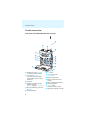
C
M
Y
CM
MY
CY
CMY
K
EK 2000
Instruction manual
Contents
Important safety instructions .......................................................................... 2
The EK 2000 diversity receiver ......................................................................... 3
The frequency bank system .......................................................................... 4
Areas of application ........................................................................................ 5
Delivery includes .................................................................................................. 5
Product overview ................................................................................................. 6
Overview of the EK 2000 diversity receiver ............................................... 6
Overview of the displays ................................................................................ 7
Putting the diversity receiver into operation ............................................... 9
Inserting the batteries/accupack ................................................................. 9
Charging the accupack .................................................................................... 9
Mounting the diversity receiver to a camera ......................................... 10
Using the diversity receiver ...........................................................................
Switching the diversity receiver on/off ..................................................
Deactivating the lock mode temporarily .................................................
Selecting a standard display .....................................................................
12
12
13
13
Using the operating menu .............................................................................
The buttons ....................................................................................................
Overview of the operating menu ...............................................................
Working with the operating menu ............................................................
14
14
15
18
Adjusting settings via the operating menu ..............................................
The main menu “Menu” ..............................................................................
The extended menu “Advanced Menu” ...................................................
The “Sync Settings” submenu ...................................................................
19
19
25
28
Synchronizing a transmitter with the receiver ......................................... 30
Using freely selectable receiving frequencies ......................................... 31
Cleaning the diversity receiver ..................................................................... 32
Recommendations and tips ........................................................................... 33
If a problem occurs ... ....................................................................................... 34
Accessories ......................................................................................................... 35
Specifications .................................................................................................... 36
Manufacturer Declarations ............................................................................. 38
Index .................................................................................................................... 40
For further information, visit the EK 2000 product page on
our website at www.sennheiser.com.
1
Important safety instructions
Important safety instructions
• Read this instruction manual.
• Keep this instruction manual. Always include this instruction manual
when passing the product on to third parties.
• Heed all warnings and follow all instructions in this instruction manual.
• Use only a cloth for cleaning the product.
• Do not place the product near any heat sources such as radiators, stoves,
or other devices (including amplifiers) that produce heat.
• Only use attachments/accessories specified by Sennheiser.
• Refer all servicing to qualified service personnel.
Servicing is required if the product has been damaged in any way, liquid
has been spilled, objects have fallen inside, the product has been
exposed to rain or moisture, does not operate properly or has been
dropped.
• WARNING: To reduce the risk of short circuits, do not use the product
near water and do not expose it to rain or moisture.
• This product is also intended for professional use. Commercial use is
subject to the safety-at-work regulations. Sennheiser, as the manufacturer, is therefore obliged to expressly point out possible health risks
arising from use.
This product is capable of producing sound pressure exceeding
85 dB(A). 85 dB(A) is the sound pressure corresponding to the
maximum permissible volume which is by law (in some countries)
allowed to affect your hearing for the duration of a working day. It is
used as a basis according to the specifications of industrial medicine.
Higher volumes or longer durations can damage your hearing. At higher
volumes, the duration must be shortened in order to prevent hearing
damage. The following are sure signs that you have been subjected to
excessive noise for too long a time:
– You can hear ringing or whistling sounds in your ears.
– You have the impression (even for a short time only) that you can no
longer hear high notes.
2
The EK 2000 diversity receiver
Replacement parts
When replacement parts are required, be sure the service technician
uses replacement parts specified by Sennheiser or those having the same
characteristics as the original part. Unauthorized substitutions may result
in fire, electric shock, or other hazards.
Intended use
Intended use of the EK 2000 diversity receiver includes:
• having read these instructions especially the chapter “Important safety
instructions”,
• using the product within the operating conditions and limitations
described in this instruction manual.
“Improper use” means using the product other than as described in this
instruction manual, or under operating conditions which differ from those
described herein.
The EK 2000 diversity receiver
This diversity receiver is part of the 2000 series. With this series,
Sennheiser offers high-quality state-of-the-art RF transmission systems
with a high level of operational reliability and ease of use. Transmitters
and receivers permit wireless transmission with studio-quality sound.
Features of the 2000 series:
• Optimized PLL synthesizer and microprocessor technology
• HDX noise reduction system
• Adaptive diversity technology
• Switching bandwidth of up to 75 MHz
• Scan function (Easy Setup) for scanning the frequency banks for unused
channels
Adaptive diversity
This diversity receiver uses the ground connection of the line cable as its
second antenna to provide improved reception.
3
The EK 2000 diversity receiver
The frequency bank system
The receiver is available in 5 UHF frequency ranges with up to
3,000 receiving frequencies per frequency range:
Range Aw:
516 – 558
500
Range Gw:
558 – 626
600
Range Bw:
626 – 698
Range Cw:
718 – 790
700
Range Dw:
790 – 865
800
Each frequency range (Aw–Dw, Gw) offers 26 frequency banks with up to
64 channels each:
Channel 1 – frequency preset
Channel 2 – frequency preset
Frequency bank 1 ... 20
Channel 64 – frequency preset
Channel 1 – freely selectable frequency
Channel 2 – freely selectable frequency
Frequency bank U1 ... U6
Channel 64 – freely selectable frequency
Each of the channels in the frequency banks “1” to “20” has been factorypreset to a fixed receiving frequency (frequency preset). The factorypreset frequencies within one frequency bank are intermodulation-free.
These frequencies cannot be changed.
For an overview of the frequency presets, please refer to the supplied
frequency information sheet. Updated versions of the frequency information sheet can be downloaded from the EK 2000 product page on our
website at www.sennheiser.com.
The frequency banks “U1” to “U6” allow you to freely select and store
receiving frequencies. It might be that these receiving frequencies are not
intermodulation-free (see page 30).
4
Delivery includes
Areas of application
The receiver can be combined with the following transmitters of the
2000 series:
Transmitter
Type
SK 2000
Bodypack transmitter
SKM 2000
Radio microphone
SKP 2000
Plug-on transmitter
For more information, visit the EK 2000 product page on our website at
www.sennheiser.com.
The transmitters are available in the same UHF frequency ranges and are
equipped with the same frequency bank system with factory-preset
frequencies. An advantage of the factory-preset frequencies is that
• a transmission system is ready for immediate use after switch-on,
• several transmission systems can be operated simultaneously on the
preset frequencies without causing intermodulation interference.
Delivery includes
The packaging contains the following items:
1 EK 2000 diversity receiver
2 AA size batteries, 1.5 V
1 CA 2 camera adapter
1 CL 500 line cable
1 CL 1 line cable
1 instruction manual
1 frequency information sheet
5
Product overview
Product overview
Overview of the EK 2000 diversity receiver
쐋
쐃
쐇
쐏
씉
쐂
쐄
씈
쐂
쐉
쐆
쐊
쐎
쐈
쐃 Headphone output (PHONES),
3.5 mm jack socket, lockable
쐇 Line output (AF OUT),
3.5 mm jack socket, lockable
(the ground contact is used by
antenna II)
쐋 Antenna I
쐏 Operation and battery status
indicator, red LED
(lit = ON, flashing = LOW BATT)
쐄 RF signal indication, green LED
(lit = RF)
쐂 Charging contacts
6
쐈
쐆 SET button
쐅
쐊 왖/왔 rocker button
(UP/DOWN)
쐎 Battery compartment
쐅 Battery compartment cover
(metal)
쐈 Battery compartment catches
쐉 Infra-red interface
씈 ON/OFF button
with ESC function (cancel)
씉 Display panel, backlit in orange
Product overview
Overview of the displays
After switch-on, the diversity receiver displays the “Frequency/Name”
standard display. For further illustrations and examples of the different
standard displays, refer to page 13.
The display backlighting is automatically reduced after approx. 20 seconds.
햲 햳
햴
햵
823.925 MHz
**2000**
RF AF P MUTE
햹
Display
햸
햶
햷
Meaning
햲 RF level “RF”
(Radio Frequency)
Diversity display:
Antenna input I is active
Antenna input II is active
Squelch threshold level
RF
햳 Audio level “AF”
(Audio Frequency)
RF signal level:
Field strength of the received signal
Modulation of the transmitter
Peak hold function
AF
When the display shows full
deflection, the audio input level
is excessively high.
For details, see page 24.
햴 Frequency
Current receiving frequency (see page 25)
햵 Name
Freely selectable name of the receiver
(see page 23)
햶 Lock mode icon
Lock mode is activated (see page 13)
7
Product overview
Display
Meaning
햷 Battery status
Charge status:
approx. 100%
approx. 70%
approx. 30%
charge status is critical, the red
LOW BATT LED 쐏 is flashing:
쐏
햸 Muting function
“MUTE”
or line output level
AF OUT
햹 Pilot tone “P”
8
“Mute” is only displayed on the “Frequency/
Name” standard display (see page 13) when
the transmitter’s RF signal is deactivated.
The diversity receiver does then not output
an audio signal.
The line output level AF OUT is only
displayed on the “Frequency bank/Channel/
Name” standard display (see page 13).
Activated pilot tone evaluation
(see page 27)
Putting the diversity receiver into operation
Putting the diversity receiver into
operation
Inserting the batteries/accupack
For powering the diversity receiver, you can either use two 1.5 V AA size
batteries or the rechargeable Sennheiser BA 2015 accupack or the DC 2
power adapter (see “Accessories” on page 35).
왘 Open the battery compartment by pushing the two catches 쐈 in the
direction of the arrows and open the cover 쐅.
쐅 쐈
쐂
쐅
쐂
왘 Insert the two batteries or the accupack as shown above. Please
observe correct polarity when inserting the batteries/accupack.
왘 Close the battery compartment by pressing on the center of the
cover 쐅.
The battery compartment cover 쐅 locks into place with an audible
click.
Charging the accupack
To charge the BA 2015 accupack:
왘 Insert the diversity receiver into the L 2015 charger (see “Accessories”
on page 35).
The L 2015 charger can only charge the combination BA 2015
accupack/diversity receiver. Standard batteries (primary cells) or
individual rechargeable battery cells cannot be charged.
9
Putting the diversity receiver into operation
Mounting the diversity receiver to a camera
Use the supplied CA 2 camera adapter to mount the receiver to a camera’s
flash mount.
왘 Determine where on the perforated plate 씉 the flash mount
adapter 씊 will need to be fastened so that the receiver can best be
attached to the camera.
씋
씊
씌
왘 At this position, place a square nut 씋 under the perforated plate 씉.
왘 Fasten the flash mount adapter 씊 to the perforated plate 씉 using the
square nut 씋.
왘 Lift one side of the belt clip 씌 as shown.
씍
왘 Press down the belt clip 씌 at one fixing point and pull it out of the
receiver housing.
왘 Repeat for the other side.
10
Putting the diversity receiver into operation
왘 Place the perforated plate 씉 onto the rear of the receiver.
왘 Reinsert the belt clip 씌.
왘 Use one of the supplied line cables to connect the line input of the
camera to the socket 쐇.
쐇
왘 Via the operating menu of the diversity receiver, adjust the level of the
line output (AF OUT) to the input of the camera (see page 24).
The ground connection of the line cable serves as the antenna for
the second diversity section. For details on the connector assignment, refer to the diagram on page 37.
왘 Connect a pair of headphones to the socket 쐃.
쐃
왘 Adjust the volume at the headphone output (PHONES) – either via the
operating menu or using the rocker button (see page 21).
11
Using the diversity receiver
Using the diversity receiver
To establish a transmission link, proceed as follows:
1. Switch the diversity receiver on (see next section).
2. Switch a transmitter on (see the instruction manual of the transmitter).
The transmission link is established and the receiver’s RF level display
“RF” 햲 reacts.
It is vital to observe the notes on frequency selection on page 30.
If you cannot establish a transmission link between transmitter and
receiver, read the chapter “Synchronizing a transmitter with the receiver”
on page 30.
Switching the diversity receiver on/off
왘 Push the two battery compartment catches 쐈 and open the battery
compartment cover 쐅.
쐏
씈
쐈
쐈
쐅
To switch the diversity receiver on:
왘 Press the ON/OFF button 씈.
The red ON LED 쐏 lights up and the standard display “Frequency/
Name” appears on the display panel.
To switch the diversity receiver off:
왘 Keep the ON/OFF button 씈 pressed until “OFF” appears on the display
panel.
The red ON LED 쐏 goes off and the diversity receiver switches off.
When in the operating menu, pressing the ON/OFF button 씈 will
cancel your entry (ESC function) and return you to the current
standard display.
12
Using the diversity receiver
Deactivating the lock mode temporarily
You can activate or deactivate the automatic lock mode via the “Auto
Lock” menu item (see page 24). If the lock mode is activated, you have to
temporarily deactivate it In order to be able to operate the receiver:
SET
왘 Press the SET button.
“Locked” appears on the display panel.
왘 Press the rocker button.
“Unlock?” appears on the display panel.
SET
왘 Press the SET button.
– When you are in the operating menu, the lock mode remains
deactivated until you exit the operating menu.
– When one of the standard displays is shown, the lock mode
is automatically activated after 10 seconds.
The lock mode icon 햶 flashes prior to the lock mode being activated again.
823.925 MHz
**2000**
RF AF P MUTE
햶
Selecting a standard display
ON/OFF
왘 Press the ON/OFF button to select a standard display.
Contents of the display
823.925 MHz
**2000**
RF AF P MUTE
Selectable standard display
“Frequency/Name”
with “MUTE” display 햸
햸
823.925 MHz
**2000**
RF AF
P MUTE
B.Ch: 1. 1
***2000***
RF AF P
0
“Transmitter Parameters”
If no transmitter is linked, “no data”
appears.
“Frequency bank/Channel/Name”
with display of the line output level
“AF OUT” 햸
햸
13
Using the operating menu
Using the operating menu
A special feature of the Sennheiser 2000 series is the consistent, intuitive
menu structure of transmitters and receivers. As a result, adjustments to
the settings can be made quickly – even in stressful situations, for example
on stage or during a live show or presentation.
The buttons
Button
Function of the button
Press the ON/OFF button • Switches the diversity receiver on and off
• Selects a standard display (see page 13)
ON/OFF
• Cancels the entry and returns to the current
standard display (ESC function)
Press the SET button
SET
Press the rocker button
14
• Changes from the current standard display
to the operating menu
• Calls up a menu item
• Enters a submenu
• Stores the settings and returns to the
operating menu
• Adjusts the volume at the headphone
output (PHONES) (see page 21)
• Changes to the next/previous menu item
• Changes the setting of a menu item
Using the operating menu
Overview of the operating menu
Submenu
“Sync Settings”
Main menu
“Menu”
Sync
Phones Volume
Squelch
Easy Setup
Frequency Preset
Name
AF Out
Auto Lock
Advanced
Exit
Display
Extended menu
“Advanced Menu”
SK Settings
SKM Settings
SKP Settings
Exit
Tune
Sync Settings
Pilot Tone
LCD Contrast
Reset
Software Revision
Exit
Submenu
“SK Settings”
“SKM Settings”
“SKP Settings”
Sensitivity
Low Cut (SKM)
Auto Lock
Mute Mode (SK, SKP)
RF Power
Phantom Power48V (SKP)
Cable Emulation (SK)
Exit
Function of the menu item
Page
Main menu “Menu”
Sync
Synchronizes a transmitter with the diversity
receiver
19
Phones Volume
Adjusts the volume at the headphone output
(PHONES)
21
Squelch
Adjusts the squelch threshold
21
Easy Setup
Scans for unused frequency presets, releases
and selects frequency presets
22
Frequency Preset
Sets the frequency bank and the channel
23
Name
Enters a freely selectable name
23
AF Out
Adjusts the level of the line output (AF OUT)
24
Auto Lock
Activates/deactivates the automatic lock
mode
24
Advanced
Calls up the extended menu “Advanced
Menu”
25
Exit
Exits the operating menu and returns to the
current standard display
–
15
Using the operating menu
Display
Function of the menu item
Page
Extended menu “Advanced Menu”
Tune
Sets the receiving frequencies for the
frequency banks “U1” to “U6”
25
Sets the frequency bank, the channel and
the receiving frequency (frequency banks
“U1” to “U6”)
25
Sync Settings
Calls up the “Sync Settings” submenu
16
Pilot Tone
Activates/deactivates the pilot tone
evaluation
27
LCD Contrast
Adjusts the contrast of the display panel
27
Reset
Resets the settings made in the operating
menu
28
Software Revision
Displays the current software revision
28
Exit
Exits the extended menu “Advanced Menu”
and returns to the main menu
–
“Sync Settings” submenu
SK Settings
Selects an SK bodypack transmitter, sets the
parameters to be transferred and activates/
deactivates the synchronization
SKM Settings
Selects an SKM radio microphone, sets the
parameters to be transferred and activates/
deactivates the synchronization
SKP Settings
Selects an SKP plug-on transmitter, sets the
parameters to be transferred and activates/
deactivates the synchronization
Exit
Exits the “Sync Settings” submenu and
returns to the extended menu “Advanced
Menu”
16
28
Using the operating menu
Display
Function of the menu item
Page
“SK Settings” / “SKM Settings” / “SKP Settings” submenu
Sensitivity
Adjusts the input sensitivity
Low Cut
Actives/deactivates the low cut filter
(“SKM Settings” only)
Auto Lock
Activates/deactivates the automatic lock
mode
Mute Mode
Sets the mode for the MUTE switch
(“SK Settings” and “SKP Settings” only)
RF Power
Adjusts the transmission power
28
PhantomPower48V Activates/deactivates the phantom
powering (“SKP Settings” only)
Cable Emulation
Emulates guitar cable capacities
(“SK Settings” only)
Exit
Exits the submenu and returns to the
“Sync Settings” submenu
17
Using the operating menu
Working with the operating menu
If the lock mode is activated, you have to deactivate it In order to
be able to work with the operating menu (see page 13).
By way of example of the “Frequency Preset” menu, this section describes
how to use the operating menu.
Changing from a standard display to the operating menu
SET
왘 Press the SET button.
The current standard display is replaced by the main menu.
The last selected menu item is displayed.
Selecting a menu item
왘 Press the rocker button to change to the “Frequency Preset”
menu item.
The current setting of the selected menu item is displayed:
Menu
Frequency Preset
B.Ch: 1. 1
Changing and storing settings
SET
SET
Menu
Frequency Preset
B.Ch: 1. 1
Frequency Preset
B.Ch: 1. 1
863.100MHz
Frequency Preset
B.Ch: 6. 3
824.500MHz
Call up “Frequency
Preset”
Select the frequency
bank and confirm
Select the channel;
store the setting
“Stored”
SET
SET
왘 Press the SET button to call up the menu item.
SET
왘 Press the rocker button to set the frequency bank.
왘 Press the SET button to confirm your selection.
SET
왘 Press the rocker button to set the channel.
왘 Press the SET button to store the setting.
18
Adjusting settings via the operating menu
Canceling an entry
ON/OFF
왘 Press the ON/OFF button to cancel the entry.
The current standard display appears on the display panel.
To subsequently return to the last edited menu item:
SET
왘 Press the SET button repeatedly until the last edited menu
item appears.
Exiting a menu item
To return to the next higher menu level:
왘 Change to the “Exit” menu item.
Menu
Exit
SET
왘 Confirm your selection.
To directly return to the current standard display:
ON/OFF
왘 Press the ON/OFF button.
Adjusting settings via the operating
menu
The main menu “Menu”
Synchronizing a transmitter with the diversity receiver – “Sync”
You can synchronize a suitable transmitter of the 2000 series with the
receiver. By default, the following parameters are transferred to the transmitter during synchronization:
Setting
Transferred parameters
“Frequency Preset” Current receiving frequency (see page 23)
“Name”
Current name set for the receiver (see page 23)
“Pilot Tone”
Current pilot tone setting of the receiver
(“Inactive”/“Active”, see page 27)
19
Adjusting settings via the operating menu
Via the “Sync Settings” submenu, you can adjust additional
parameters to be transferred to the transmitters (see page 16
and 28).
To transfer these parameters:
왘 Switch the transmitter and the diversity receiver on.
왘 On the receiver, call up the “Sync” menu item.
“Sync” appears on the display panel of the receiver.
왘 Place the infra-red interface of the transmitter (see the instruction
manual of the transmitter) in front of the infra-red interface of the
receiver 쐉.
쐉
The parameters are transferred to the transmitter. When the transfer
is completed, “ ” appears on the display panel of the diversity
receiver. The receiver then switches back to the current standard
display.
To cancel the transfer:
왘 Press the ON/OFF button 씈 on the receiver.
“ ” appears on the display panel of the receiver. “ ” also appears if:
– no transmitter was found or the transmitter is not compatible,
– no transmitter was found and the synchronization process was
canceled after 30 seconds,
– you canceled the transfer.
20
Adjusting settings via the operating menu
Adjusting the volume at the headphone output –
“Phones Volume”
There are two ways to adjust the volume at the headphone output
(PHONES):
CAUTION!
Hearing damage due to high volumes!
Listening at high volume levels for long periods can lead
to permanent hearing defects.
왘 Set the volume to a low level before putting the headphones on
왘 Do not continuously expose yourself to high volumes.
1. When one of the standard displays is shown on the display panel:
왘 Press the rocker button to adjust the volume at the headphone output (PHONES).
2. When you are in the operating menu:
SET
Menu
Phones Volume
5
Phones Volume
5
Phones Volume
10
Call up “Phones
Volume”
Select the desired
setting
Store the setting
SET
“Stored”
Adjustment range: 0 to 50
Adjusting the squelch threshold – “Squelch”
SET
Menu
Squelch
5 dB
Call up “Squelch”
Squelch
5 dB
Squelch
13 dB
Select the
desired setting
Store the setting
SET
“Stored”
Adjustment range: 5 to 25 dBμV, adjustable in 2-dB steps, can be switched
off
The squelch eliminates annoying noise when the transmitter is switched
off or when there is no longer sufficient transmitter power received by the
receiver.
21
Adjusting settings via the operating menu
CAUTION!
Danger of hearing damage!
If you switch the squelch off or adjust the squelch
threshold to a very low value, loud hissing noise can occur
in the receiver. The hissing noise can be loud enough to
cause hearing damage!
왘 Always make sure that the squelch is switched on.
왘 Before adjusting the squelch threshold, set the
volume of the headphone output PHONES to the
minimum (see page 21).
왘 Never change the squelch threshold during a live
transmission.
왘 Adjust the squelch threshold – with the transmitter switched off – to
the lowest possible setting that suppresses hissing noise.
A high squelch threshold reduces the transmission range.
The squelch should only be switched off for servicing purposes. With the
squelch threshold set to “5 dB”, you switch the squelch off by keeping the
DOWN rocker button pressed for 3 seconds.
Display
햻
Squelch is ...
823.925 MHz
**2000**
... switched on.
823.925 MHz
**2000**
... switched off.
P MUTE
RF AF
햻
RF AF P
The dotted line 햻 displays the squelch
threshold.
The dotted line 햻 goes off and the audio
level display “AF” shows full deflection
(hissing noise).
If you have accidentally switched off the squelch:
왘 Press the UP rocker button to switch the squelch on.
Scanning for, releasing and selecting frequency presets –
“Easy Setup”
Menu item
Function of the menu item
Reset List
Releases all locked frequency presets
Current List
Selects an unused frequency preset
22
Adjusting settings via the operating menu
Menu item
Function of the menu item
Scan New List Automatically scans for unused receiving frequencies
(frequency preset scan)
If receiving frequencies are used, they will be locked; if
receiving frequencies are unused, they will be released.
After the frequency preset scan, you can select an unused
frequency preset.
Selecting the frequency bank and the channel – “Frequency Preset”
SET
SET
Menu
Frequency Preset
B.Ch: 1. 1
Frequency Preset
B.Ch: 1. 1
863.100MHz
Frequency Preset
B.Ch: 6. 3
824.500MHz
Call up “Frequency
Preset”
Select the frequency
bank and confirm
Select the channel;
store the setting
“Stored”
SET
When setting up multi-channel systems, please observe the
following:
Only the factory-preset receiving frequencies within one
frequency bank (“1” to “20”) are intermodulation-free. It is vital
to observe the notes on frequency selection on page 30.
Overview of the frequency banks and channels:
Frequency bank
Channels
Type
“1” to “20”
up to 64 per
frequency bank
System bank:
frequencies are factory-preset
“U1” to “U6”
up to 64 per
frequency bank
User bank:
frequencies are freely selectable
Entering a name – “Name”
Menu
Name
Lichael
Call up “Name”
Name
Lichael
Enter a character
and confirm
Name
Michael
Enter a character;
store the setting
“Stored”
23
Adjusting settings via the operating menu
Via the “Name” menu item, you can enter a freely selectable name (e.g. the
name of the performer) for the receiver. The name is displayed on the
standard display (see page 7). The name can consist of up to 8 characters
such as:
• letters (without pronounciation marks),
• numbers from 0 to 9,
• special characters and spaces.
To enter a name, proceed as follows:
SET
왘 Press the rocker button to select a character.
왘 Press the SET button to change to the next segment/character
or to store the complete entry.
Adjusting the audio output level – “AF Out”
SET
Menu
AF Out
AF Out
0 dB
0 dB
Call up “AF Out”
Select the desired
setting
AF Out
+ 60dB
dB
Store the setting
SET
“Stored”
Adjustment range: –24 dB to +18 dB, adjustable in 6-dB steps
Via the “AF Out” menu item, you can adjust the level of the audio output
from the receiver to the input of the connected camera.
Activating/deactivating the automatic lock mode – “Auto Lock”
SET
Menu
Auto Lock
Active
Call up
“Auto Lock”
Auto Lock
Active
Select the desired
setting
Auto Lock
Inactive
Store the setting
SET
“Stored”
The lock mode prevents that the volume at the headphone output PHONES
is accidentally adjusted. In addition, the lock mode prevents that the diversity receiver is accidentally switched off or programed during operation.
The lock mode icon 햶
the current standard display indicates that the
lock mode is activated. For information on how to use the lock mode, refer
to page 13.
24
Adjusting settings via the operating menu
The extended menu “Advanced Menu”
To get into the extended menu “Advanced Menu”:
왘 From the main menu, select “Advanced”.
Setting the receiving frequencies and the frequency banks “U1”
to “U6” – “Tune”
When you have selected one of the system banks and then select
the “Tune” menu, the diversity receiver automatically switches to
channel 1 of the frequency bank “U1”. In this case, “U1.1” briefly
appears on the display panel.
Upon delivery, the channels of the frequency banks “U1” to “U6”
are not assigned a receiving frequency.
Via the “Tune” menu item, you can set a receiving frequency to be stored
in the current channel or you can select a different channel in one of the
frequency banks “U1” to “U6” and assign this channel a receiving
frequency.
Setting a receiving frequency for the current channel
SET
왘 Press the rocker button until the “Tune” menu item appears.
왘 Press the SET button.
The MHz section of the receiving frequency of the channel is
highlighted.
SET
SET
Advanced Menu
Tune
823.925 MHz
Tu n e
823.925 MHz
B.Ch: U1. 1
Tu n e
823.925 MHz
B.Ch: U1. 1
Call up “Tune”
(special function)
Select the frequency
bank and confirm
Select the channel;
store the setting
“Stored”
SET
It is vital to observe the notes on frequency selection on page 30.
왘 Press the rocker button to set the MHz section of the
frequency.
SET
왘 Press the SET button to confirm the MHz section of the
frequency.
The kHz section of the frequency is highlighted.
왘 Press the rocker button to set the kHz section of the frequency.
25
Adjusting settings via the operating menu
SET
왘 Press the SET button to confirm the frequency.
“Stored” appears on the display panel. The “Tune” menu item
appears again.
Selecting a channel and assigning this channel a frequency
SET
왘 Press the rocker button until the “Tune” menu item appears.
왘 Press the SET button and keep it pressed until the frequency
bank is highlighted.
SET
Advanced Menu
Tune
823.925 MHz
Call up “Tune”
(special function)
SET
Tu n e
823.925 MHz
B.Ch: U1. 1
Tu n e
823.925 MHz
B.Ch: U5. 1
Select the frequency
bank and confirm
Select the channel;
store the setting
“Stored”
SET
SET
왘 Press the rocker button to set the frequency bank.
왘 Press the SET button to confirm the frequency bank.
The channel is highlighted.
SET
왘 Press the rocker button to set the channel.
왘 Press the SET button to confirm the channel.
The frequency (MHz section) is highlighted.
왘 Set the desired frequency (MHz and kHz section) as described in the
previous chapter.
26
Adjusting settings via the operating menu
Activating/deactivating the pilot tone evaluation – “Pilot Tone”
Advanced Menu
Name
Pilot Tone
Active
Call up
“Pilot Tone”
Pilot
Active
Pilot
Inactive
Select the desired
setting
Store the setting
“Stored”
The transmitter adds an inaudible signal, known as the pilot tone, to the
transmitted signal. The diversity receiver detects and evaluates the pilot
tone.
The pilot tone supports the diversity receiver’s squelch function, thus
protecting against interference due to RF signals from other devices.
Display
Meaning
No icon
The pilot tone evaluation is deactivated.
The pilot tone evaluation is activated but the receiver does
not receive a pilot tone.
The pilot tone evaluation is activated. The receiver receives
a pilot tone.
Adjusting the contrast of the display panel – “LCD Contrast”
Advanced Menu
Name
LCD Contrast
7
Call up
“LCD Contrast”
LCD Contrast
7
LCD Contrast
10
Select the desired
setting
Store the setting
“Stored”
You can adjust the contrast of the display panel in 16 steps.
27
Adjusting settings via the operating menu
Resetting the settings made in the operating menu – “Reset”
SET
Advanced Menu
Reset
Reset
Yes
Select the desired
setting; apply the
setting
Call up “Reset”
“Stored”
SET
When resetting the settings made in the operating menu, only the
selected settings for the pilot tone and for the frequency banks “U1” to
“U6” remain unchanged. For an overview of the factory-preset default
settings, refer to the enclosed frequency information sheet.
Displaying the software revision – “Software Revision”
You can display the current software revision of the diversity receiver.
The “Sync Settings” submenu
Display
Function
SK Settings
Calls up the “SK Settings” submenu
SKM Settings Calls up the “SKM Settings” submenu
SKP Settings
Calls up the “SKP Settings” submenu
Exit
Exits the “Sync Settings” submenu and returns to the
extended menu “Advanced Menu”
“SK Settings”, “SKM Settings” and “SKP Settings”
Via the “SK Settings”, “SKM Settings” and “SKP Settings” submenus, you
can set the transmitter parameters directly on the diversity receiver and
activate or deactivate the transfer of these parameters to the transmitter.
Setting
Sensitivity
– 6dB
Sync
Sensitivity
– 6dB
Sync
28
Transfer is ...
... activated
... deactivated
Adjusting settings via the operating menu
Via the “Sync” menu item, you can transfer the parameters from the
receiver to the transmitters via the infra-red interface (see page 19).
Display
Function
Sensitivity
Adjusts the input sensitivity:
Settings
SK
–60 dB to 0 dB,
adjustable in steps of 3 dB
SKM and SKP
–48 dB to 0 dB,
adjustable in steps of 6 dB
Low Cut
(SKM only)
Low cut filter
Auto Lock
Lock mode
Inactive, Active
Mute Mode
(SK, SKP only)
Mute mode
Disabled, RF On/Off,
AF On/Off
RF Power
Transmission power
Low, Standard, High
/
PhantomPower48V Phantom powering
(SKP only)
Inactive, Active
Cable Emulation
(SK only)
Minimum, Low, Medium,
High
Emulates guitar cable
capacities
29
Synchronizing a transmitter with the receiver
Synchronizing a transmitter with the
receiver
When synchronizing a transmitter with a diversity receiver, please
observe the following:
왘 Only use a transmitter and a diversity receiver from the same
frequency range (see the type plates on the transmitter and
the diversity receiver).
왘 Make sure that the desired frequencies are listed in the
enclosed frequency information sheet.
You can also contact your Sennheiser partner who will be
pleased to calculate intermodulation-free frequencies for you.
왘 Make sure that the desired frequencies are approved and legal
in your country and, if necessary, apply for an operating
license.
Upon delivery, transmitter and diversity receiver are synchronized with
each other. If, however, you cannot establish a transmission link between
transmitter and diversity receiver, you have to synchronize the channels of
the devices:
왘 Deactivate the RF signal on all transmitters (see the instruction manual
of the transmitter).
This prevents that, during the frequency scan, the channels used by
switched-on transmitters are displayed as “used”.
왘 With a diversity receiver, perform a frequency preset scan to scan the
frequency banks for unused channels (“Scan New List”, see page 23).
왘 Select a frequency bank and a channel on this diversity receiver
(“Current List”, see page 22).
If you want to set up a multi-channel system, select a frequency bank
with a sufficient number of unused channels for all planned transmission links.
Via the “Sync Settings” submenu, you can set additional transmitter
parameters directly on the diversity receiver and activate or deactivate
the transfer of these parameters to the transmitter (see page 28).
왘 Synchronize a transmitter with the diversity receiver (see page 19).
The receiver’s frequency, name, pilot tone setting and, where applies,
additional parameters activated via the “Sync Settings” submenu are
transferred to the transmitter.
30
Synchronizing a transmitter with the receiver
OR:
왘 Manually set the transmitter to the same frequency bank and channel
that you set on the receiver.
왘 Activate the RF signal on this transmitter.
The transmission link is established.
If you want to set up a multi-channel system:
왘 Repeat the following 4 steps for each additional transmission link:
– Perform a frequency preset scan with the next diversity receiver.
– Select a channel from the same frequency bank as with the first
diversity receiver.
– Synchronize a transmitter with the diversity receiver.
– Activate the RF signal on the transmitter.
Using freely selectable receiving frequencies
You can also freely select the receiving frequencies and store these
frequencies in the frequency banks “U1” to “U6”.
It might be that the freely selected frequencies are not intermodulation-free
If you are using frequencies from the frequency banks “U1” to
“U6”, it might be that the receiving frequencies are not intermodulation-free.
왘 Contact your Sennheiser partner who will be pleased to
calculate intermodulation-free frequencies for you (see
www.sennheiser.com).
왘 Set each diversity receiver to the same frequency bank (“U1” to “U6”).
왘 On one of the receivers, select a channel within this frequency bank and
assign this channel a receiving frequency (see page 25).
왘 Synchronize a transmitter with this receiver (see the instruction
manual of the transmitter).
OR:
왘 Manually set the transmitter to the same frequency bank and channel
that you set on the receiver.
왘 Repeat for the remaining transmitters and receivers as described
above.
31
Cleaning the diversity receiver
Cleaning the diversity receiver
CAUTION!
Liquids can damage the electronics of the receiver!
Liquids entering the housing of the device can cause a
short-circuit and damage the electronics.
왘 Keep all liquids away from the receiver.
왘 Do not use any solvents or cleansing agents.
왘 Use a cloth to clean the diversity receiver from time to time.
32
Recommendations and tips
Recommendations and tips
... for the diversity receiver
• Make sure that the antenna and the headphone or line cable do not
cross.
• For best results, make sure that the transmitter sensitivity is correctly
adjusted.
... for optimum reception
• Transmission range depends to a large extent on location and can vary
from about 10 m to about 150 m. There should be a “free line of sight”
between transmitting and receiving antennas.
• To avoid overloading the receiver, observe a minimum distance of 5 m
between transmitting and receiving antennas.
... for multi-channel operation
• When operating a multi-channel system, you should only use the channels within one frequency bank. Each of the frequency banks “1” to
“20” accommodates factory-preset frequencies which are intermodulation-free.
• The frequency banks “U1” to “U6” allow you to freely select and store
receiving frequencies (see page 25).
• When using several transmitters simultaneously, interference can be
avoided by maintaining a minimum distance of 20 cm between two
transmitters.
33
If a problem occurs ...
If a problem occurs ...
Problem
Possible cause
Possible solution
Diversity
receiver
cannot be
operated,
“Locked”
appears on
the display
panel
Lock mode is activated
Deactivate the lock mode
(see page 13).
No operation
indication
Batteries are flat or
accupack is flat
Replace the batteries or
recharge the accupack
(see page 9).
No RF signal
Transmitter and
receiver are not on
the same channel
Set the transmitter and
receiver to the same channel.
Transmission range is
exceeded
Check the squelch threshold
setting (see page 21).
Synchronize the transmitter
with the receiver
(see page 30).
Reduce the distance between
transmitter and receiver.
RF signal is deactivated Activate the RF signal
(“RF Mute“)
(see the instruction manual
of the transmitter).
RF signal
available, no
audio signal,
“MUTE”
appears on
the display
panel
Transmitter is muted
Cancel the muting
(see the instruction manual
of the transmitter).
Receiver’s squelch
threshold is adjusted
too high
Reduce the squelch threshold
setting (see page 21).
Transmitter doesn’t
transmit a pilot tone
Deactivate the pilot tone
evaluation (see page 27).
Audio signal
has a high
level of background noise
Transmitter sensitivity
is adjusted too low
Adjust the transmitter
sensitivity correctly
(see the instruction manual
of the transmitter).
34
Accessories
Problem
Possible cause
Audio signal is Transmitter sensitivity
distorted
is adjusted too high
Possible solution
Adjust the transmitter
sensitivity correctly
(see the instruction manual
of the transmitter).
Receiver’s audio output Reduce the audio output level
level is adjusted too
(“AF Out”, see page 24).
high
No access
to a certain
channel
During scanning,
an RF signal has been
detected on this
channel and the
channel has been locked
Set the transmitter operating
on this channel to a different
channel and redo the
frequency preset scan
(see page 22).
During scanning, a
transmitter of your
system operating on
this channel has not
been switched off
Switch the transmitter off and
redo the frequency preset scan
(see page 22).
If a problem occurs that is not listed in the above table or if the problem
cannot be solved with the proposed solutions, please contact your local
Sennheiser partner for assistance.
To find a Sennheiser partner in your country, search at
www.sennheiser.com under “Service & Support”.
Accessories
The following EK 2000 accessories are available from your specialist
dealer:
009950
BA 2015 accupack
009828
L 2015 charger
009827
DC 2 power adapter for external DC powering (12 V)
009986
CA 2 camera adapter
005022
CL 1 line cable (jack to jack, balanced)
087047
CL 500 line cable (XLR-3 to jack, balanced)
35
Specifications
Specifications
RF characteristics
Modulation
Frequency ranges
Receiving frequencies
Switching bandwidth
Nominal/peak deviation
Receiver principle
Sensitivity
(with HDX, peak deviation)
Adjacent channel rejection
Intermodulation attenuation
Blocking
Squelch
Pilot tone squelch
wideband FM
516–558, 558–626, 626–698,
718–790, 790–865 MHz
(Aw to Dw, Gw, see page 4)
up to 3,000 receiving frequencies,
tuneable in steps of 25 kHz
20 frequency banks, each with up
to 64 factory-preset channels
6 frequency banks, each with up
to 64 user programmable channels
up to 75 MHz
±24 kHz/±48 kHz
adaptive diversity
< 4 μV, typ. 1.6 µV for 52 dBArms S/N
typ. ≥ 80 dB
typ. ≥ 78 dB
≥ 80 dB
Off, 5 to 25 dBμV,
adjustable in steps of 2 dB
can be switched off
AF characteristics Line
Compander system
S/N ratio
(1 mVRF, peak deviation)
Sennheiser HDX
Line: ≥ 120 dBArms
Phones: approx. 90 dBArms
THD
AF output voltage
(at peak deviation, 1 kHz AF)
Output power at 2.4 V, 5% THD
and nominal deviation
Adjustment range of
line output level
≤ 0.9%
Line: 3.5 mm jack socket: +17 dBu
(mono, balanced)
36
Phones: 2 x 12 mW at 32 Ω
42 dB, adjustable in steps of 6 dB
Specifications
Overall device
Temperature range
Power supply
Nominal voltage
Power consumption:
–10°C to +55°C
2 AA size batteries, 1.5 V
or BA 2015 accupack
2,4 V
• at nominal voltage
typ. 180 mA (30 mW)
• with switched-off receiver
Operating time (line operation)
Dimensions
Weight (incl. batteries)
≤ 25 μA
typ. 9 hrs
approx. 82 x 64 x 24 mm
approx. 130 g
In compliance with
Europe
EMC:
EN 301489-1/-9
Radio: EN 300422-1/-2
Safety: EN 60065
USA
47 CFR 15 subpart B
Approved by
Canada
Industry Canada RSS 123
IC 2099A-EK2000
limited to 806 MHz
Connector assignment
3.5 mm jack plug
Line
Phones
wired balanced
wird in parallel
+ –
+ +
37
Manufacturer Declarations
Manufacturer Declarations
Warranty
Sennheiser electronic GmbH & Co. KG gives a warranty of 24 months on this
product.
For the current warranty conditions, please visit our web site at
www.sennheiser.com or contact your Sennheiser partner.
In compliance with the following requirements
• RoHS Directive (2002/95/EC)
• WEEE Directive (2002/96/EC)
Please dispose of the diversity receiver at the end of its operational lifetime by taking it to your local collection point or recycling center for such equipment.
• Battery Directive (2006/66/EC)
The supplied batteries or rechargeable batteries can be recycled.
Please dispose of them as special waste or return them to your
specialist dealer. In order to protect the environment, only
dispose of exhausted batteries.
CE Declaration of Conformity
0682
•
• R&TTE Directive (1999/5/EC)
The declarations are available at www.sennheiser.com.
Before putting the device into operation, please observe the respective
country-specific regulations.
38
Manufacturer Declarations
Statements regarding FCC and Industry Canada
This device complies with Part 15 of the FCC Rules and with RSS-210 of
Industry Canada. Operation is subject to the following two conditions: (1)
this device may not cause harmful interference, and (2) this device must
accept any interference received, including interference that may cause
undesired operation.
This equipment has been tested and found to comply with the limits for a
Class B digital device, pursuant to Part 15 of the FCC Rules. These limits are
designed to provide reasonable protection against harmful interference in
a residential installation. This equipment generates, uses and can radiate
radio frequency energy and, if not installed and used in accordance with
the instructions, may cause harmful interference to radio communications.
However, there is no guarantee that interference will not occur in a particular installation. If this equipment does cause harmful interference to
radio or television reception, which can be determined by turning the
equipment off and on, the user is encouraged to try to correct the interference by one or more of the following measures:
• Reorient or relocate the receiving antenna.
• Increase the separation between the equipment and receiver.
• Connect the equipment into an outlet on a circuit different from that to
which the receiver is connected.
• Consult the dealer or an experienced radio/TV technician for help.
This class B digital device complies with the Canadian ICES-003.
Changes or modifications made to this equipment not expressly approved
by Sennheiser electronic Corp. may void the FCC authorization to operate
this equipment.
Before putting the device into operation, please observe the respective
country-specific regulations!
39
Index
Index
Accessories
35
Accupack
charging
inserting
9
9
Easy Setup (scanning for, releasing
and selecting frequency
presets) 22
F
Frequency bank
selecting 23
setting a frequency 25
~ system 4
AF Out (adjusting the audio output
Frequency Preset (selecting a
level) 24
frequency bank/
Auto Lock (activating/deactivating
channel) 23
the lock mode) 24
Advanced Menu (extended menu)
overview 16
settings 25
B
Batteries
battery status
inserting 9
8
Buttons
function of the ~ 14
ON/OFF button 6
SET button 6
UP/DOWN button 6
C
Channel
assigning a frequency 26
selecting 23
setting a frequency 25
D
Frequency presets
releasing (Reset List) 22
searching for unused ~ (Scan New
List) 22
selecting (Current List) 22
H
Headphones, adjusting the
volume 21
L
LCD Contrast (adjusting the
contrast of the display
panel) 27
Lock mode
activating/deactivating (Auto
Lock) 24
deactivating temporarily 13
Displays
lock mode icon 7
adjusting the contrast of the disLocked
13
play panel (LCD Contrast) 27
AF (audio level) 7
LOW BATT 6
AF OUT 8
M
LOW BATT 8
Menu 15
MUTE 8
Menu (main menu)
overview 7
overview 15
RF (RF level) 7
settings 19
standard displays 13
N
E
Name (entering a name) 23
O
40
Index
Operating menu
overview 15
settings 19
using 18
P
Phones Volume (adjusting the
volume at the headphone
output) 21
Reset (resetting the settings made
in the operating menu) 28
RF signal indication
S
6
Software Revision (displaying the
software revision) 28
Squelch (adjusting the
squelch) 21
Pilot Tone (activating/deactivating
Sync (synchronizing a transmitter
the pilot tone
with the receiver) 19
evaluation) 27
T
R
Transmitter (synchronizing with
Receiver
receiver) 30
cleaning 32
Troubleshooting
34
mounting to a camera 10
Tune
(setting
the
receiving
switching off 12
frequencies and the
switching on 12
frequency banks) 25
41
C
M
Y
CM
MY
CY
CMY
K
Sennheiser electronic GmbH & Co. KG
Am Labor 1, 30900 Wedemark, Germany
www.sennheiser.com
Printed in Germany
Publ. 01/09
529668/A01