1
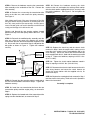
#7600058 TRANSMISSION PULLEY KIT FOR
SEARS / SIMPLICITY ZT RIDING MOWERS
WARNING
!
!
DO NOT attempt any adjustments, maintenance, repairs, or service with engine running. Stop engine. Engage
parking brake. Remove key. Remove spark plug wire and secure wire away from spark plug. Engine, muffler and
surrounding areas are extremely hot. Avoid serious burns; allow components to cool down before installing kit.
Replace worn or damaged parts prior to operating. Use approved fuel container. DO NOT smoke near open fuel
container. DO NOT fill fuel tank indoors or when engine is running. Allow engine to cool for at least ten minutes
before refilling. Make sure that fuel cap is tightened securely. Wipe off any spilled fuel before starting engine.
Kit Contents - 7600058 Transmission Pulley Kit
7027266 - 7/16-20 x 3 Hex Head Cap Screw (1)
1732224 - Transmission Belt (1)
7101716 - Engine Pulley (1)
7072080 - Wire Tie (1)
7101717 - Clutch Retainer (1)
STEP 1: Lower the mowing deck to its lowest cutting position. Refer to the unit’s Operator’s Manual for instructions.
STEP 2: Remove the mowing deck belt from the electric
clutch pulley. Refer to the unit’s Operator’s Manual for
instructions.
STEP 3: Carefully cut the wire tie securing the electric clutch
harness to the clutch retainer. Then disconnect the electric
clutch harness from the unit’s main electric harness. See
Figure 1.
Remove idler spring end
STEP 4: Remove the hardware securing the electric clutch
to the engine shaft. Remove the clutch and clutch key from
the engine shaft. See Figure 1.
FIGURE 2
STEP 7: Remove the engine pulley assembly from the
engine shaft, and replace with the engine pulley assembly
supplied with this kit. See Figure 3.
Remove
belt
Remove hardware and clutch
Disconnect harness
FIGURE 1
Replace with
supplied
engine pulley
STEP 5: Remove the forward end of the transmission idler
spring from the shoulder bolt mounted to the underside of
the unit. See Figure 2.
FIGURE 3
STEP 6: Remove the transmission belt from the engine
pulley and the two transmission pulleys. See Figure 3.
Note: The transmission belt is retained in the idler assembly
by the idler belt guide, and therefore cannot be removed
from the idler assembly at this time.
INSTRUCTION No. 7101803 (I.R. 10/31/2007)
TP 200-5303-IR-AT-SC
1
STEP 8: Remove the hardware securing the transmission
idler assembly to the underside of the unit. Remove the
idler assembly.
STEP 14: Remove the hardware securing the clutch
retainer to the unit, and replace the existing clutch retainer
with the clutch retainer supplied with this kit, securing it with
the existing hardware. See Figure 5. Do not tighten the
hardware yet.
STEP 9: Remove the nut securing the transmission idler
pulley to the idler arm, and remove the pulley assembly.
See Figure 4.
Note: Make careful note of the exact placement of the idler
belt guide before removing hardware, as the belt guide must
be in this same position upon reassembly. Incorrect placement of the belt guide can result in interference with the belt
routing and damage to the belt and/or unit.
Replace with
supplied
clutch retainer
Remove and discard the two spacing washers located
between the top of the idler pulley and the idler arm. See
Figure 4.
STEP 10: Reinstall the modified pulley assembly onto the
idler arm, while at the same time replacing the existing
transmission belt with the transmission belt supplied in this
kit. Secure with the nut removed in Step 9, and position the
belt guide as shown in Figure 4. Tighten the hardware
securely.
FIGURE 3
STEP 15: Replace the clutch key and the electric clutch
removed in Step 4 onto the engine shaft, making sure to
insert the clutch retainer into the corresponding slot in the
clutch housing. Secure the clutch with the hex head cap
screw supplied with this kit, fitted with the washers removed
in Step 4. Tighten the hardware, torquing to 45-55 ft. lbs.
(61.2-74.8 Nm.).
Idler Arm
(Removed
from unit)
Remove and
discard these
washers
STEP 16: Tighten the clutch retainer hardware noted in
Step 14, torquing to 24-36 ft. lbs. (32.4-48.6 Nm.)
Idler Pulley
1/16 - 1/8”
clearance
Belt Guide
Positioning
STEP 17: Reconnect the electric clutch harness to the unit’s
main wiring harness, and secure the clutch harness up
against the clutch retainer with the supplied wire tie, as
removed in Step 3.
Belt
STEP 18: Replace the mowing deck belt removed in Step 1
onto the electric clutch pulley. Refer to the unit’s Operator’s
Manual for instructions.
FIGURE 4
STEP 11: Reinstall the idler assembly onto the underside of
the unit with the hardware removed in Step 8. Tighten the
hardware securely.
Assembly is complete.
STEP 12: Install the new transmission belt onto the two
transmission pulleys and the engine pulley, as removed in
Step 6.
STEP 13: Replace the forward end of the transmission idler
spring onto the shoulder bolt, as removed in Step 5.
INSTRUCTION No. 7101803 (I.R. 10/31/2007)
TP 200-5303-IR-AT-SC
2