1
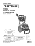
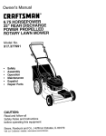
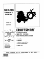
OWNER'S
MANUAL
MODEL
NO.
580.751500
_®
5 HORSEPOWER
1800 PS!
2.5 GPM
HiGH PRESSURE WASHER
HOURS:
Mon.- Frl. 8 a,m. to 5 p.m
(CST)
o
Assembly
=
Operation
.
Customer Responsibilities
CAUTION:
Read and Follow
•
Service and Adjustment
all Safety Rules
and Instructions
o
Repair Parts
Before Operating
This Equipment
SEARS,
ROEBUCK
and
CO.,
HoffmanEstates,'
IL
60179
U.S.A.
SAFETY RULES
CAUTION: ALWAYS DISCONNECT SP/_K PLUG WIRE AND PLACE WIRE WHERE IT CANNOT CONTACT SPARK PLUG, TO PREVENT ACCIDENTAL STARTING WHEN SETTING UP, TRANSPORTING,
ADJUSTING OR MAKING REPAIRS TO YOUR HIGH PRESSURE WASHER,
_'
TRAINING:
Engine exhaust gases contain DEADLY carbon monoxide gas. l_is dangerous gas, if breathed in sufficient concentrations, can cause unconsciousnessor
even death. Operate this equipment only in the open
air where adequate ventilationis availabteo
= Gasoline is highly FIJ_M_L&.BLEand its vapors are
EXPLOSIVE. Do not permit smoking, open flames,
sparks or heat in the vicinity while handlinggasoline.
Avoid spilling gasoline on a hot engine. Allow unit to
cool for 2 minutes before refueling. Comply with all
laws regulating storage and handhng of gasoline_
= Locate this pressure washer in areas away from combustible materials, combustiblefumes or dust=
= The high pressure equipment is designed to be used
with Sears authorized parts only. If you use this
equipment with parts that do not complywith minimum
specifications, the user assumes all nsks and liabilities.
•
Some chemP-.atsor detergents may be harmful if
inhaled or ingested, causing severe nausea, fainting
or poisoning. The harrr_,_!elements may cause prop.
erty damage or severe injury.
•
Do not allow CHILDREN to operate the Pressure
Washer at any time.
•
=
=
_'
='
=
"
q'
PREPARATION:
•
Operate engine onlyat governedspeed. Runningthe
engine at excessive speeds increases the hazard of
personal injury. Do not tamper with parts which may
increase or decrease the governed speed.
=
Do not wear loose clothing, jewelry or anything that
may be caught in the starter or other rotatingparts.
"
Before starting the Pressure Washer in cold weather,
check al! parts of the equipment and be sure ice has
not formed there.
•
Units with broken or missing parts, or without protective housing or covers should NEVER be operated°
"
The muffler and air cleaner must be installed and in
j_oodconditionbeforeoperatingthe PressureWasher.
hese components act as spark arrestors ifthe engine
backfires.
•
Check the fuel system for leaks or signs of deterioration such as chafed or spongy hose, loose or missing
clamps or damaged tank or cap. Correct all defects
before operating the Pressure Washer.
"
=
_,
_'
='
o
•
MAINTENANCE
='
='
OPERATION:
"
Do not spray flammable liquids.
•
Never aim the gun at people, animals or plants.
•
Never allow any part of the body to come in contact
with the fluid stream. DO NOT come in contact with a
fluid stream created by a leak in the high pressure
hose_
o High pressure stream of fluidthat this equipment can
produce can pieme skin and its undertyingtissues,
leading to sedous injuryand possibleamputation.
°
High pressure spray can cause paint chips or other
particlesto become airborne and fly at high speeds.
AND STORAGE:
Operate and store this unit on a stable surface.
High pressure hose can develop leaks from wear,
kinking, abuse, etc. Water spraying!from a leak is
capable of injecting material into skin. inspect hose
each time before using it. Check all hoses for cuts,
leaks, abrasions or bulging of cover, or dama_]e or
movement of couplings. If any of these conditions
exist, replace hose immediately. Never repair high
pressure hose. Replace it with another hose that
meets minimum pressure rating of your pressure
washer.
J
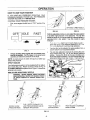
LOOK FOR THIS SYMBOL
SAFETY PRECAUTIONS.
COME ALERT!!!
YOUR
Always wear'eye protectionwhen you use this equipment or when you are in the vicinity where the equipment is in use.
Operate the pressure at no more than the PSI fluid
pressure rated for your pressure washer.
Never move the machine by putling on the high pressure hose. Use the handle provided on the top of the
uniL
Always be certain the spray gun, nozzles and accessories are correctly attached.
Never use a spray gun which does not have a trigger
lock or triggerguard in place and in working order.
Use a respiratoror mask whenever there is a chance
that vapors may be inhaled. Read all instructionswith
the mask so you are certain the mask will provide the
necessary protectionagainst inhaling harmful vapors_
High pressurespray may damage fragile items includingglass. Do not point spray gun at glass when in the
jet spray mode.
Keep the hose connected to machine or the spray gun
while the system is pressurized. Disconnecting the
hose while the unit is pressurized is dangerous,
Hold the spray gun firmlyin your hand before you start
the uniL Failureto do so could result in an injuryfrom
a whipping spray gun. Do not leave the spray gun
unattendedwhile the machine is running.
The cleaning area should have adequate slopes and
drainage to reduce the possibility of a fall due to
slipperysurfaces°
Keep water spray away from electric wiring or fatal
electricshock may resulL
DO not adjust unloader valve to a pressure in excess
of machine rating°
Do not secure trigger gun in the pull-back (open)
position.
Do not by@ass any safety device on this machine°
DO not leave trigger closed for more than 5 minutes
with engine running. This could damage the pump.
The muffler and engine heat up during operation and
remain hot immediately after shutting it down° Avoid
contact with a hot muffler or engine or you could be
severely bumed.
TO POINT OUT IMPORI"ANT
IT MEANS
"ATTENTIONH!
SAFETY IS INVOLVED."
2
BE-
CONGRATULATIONS on your purchase of a Sears Craftsman high pressure washer. It has been designed, engineered and manufactured to give you the best possible
dependability and performance.
Should you experience any problem you cannot easily
remedy, please contact your nearest Sears Service CentedDepartment or call the 1-800 number listed on the front
of this manual. We have competent, welt-trained techni.
clans and the proper tools to service or repair this uniL
Please read and retain this manual. The instructions wilt
enable you to assemble and maintain your high pressure
washer properly. Always observe the =SAFETY RULES."
PRODUCT
S PECIFICATIONS
Pressure Washer Specifications
PUMP PRESSURE
Adjustable to 1800 ps!
FLOW RATE
2.5 gpm
DETERGENT MIX
Use undiluted detergent
DETERGENT
Adjustable to 66:!
RATIO
WATER SUPPLY
TEMPERATURE
Not to exceed 140°F
SUCTION HEIGHT
3 FT'. maximum
MODEL
NUMBER
580,751500
SERIAL
NUMBER
RATED HORSEPOWER
5
DISPLACEMENT
12.6 cu. inches
SPARK PLUG:
DATE OF
PURCHASE ....
MAINTENANCE
Type:
Set Gap To.
THE MODEl.. AND SERIAL NUMBERS WILL BE
FOUND ON A DECAL ATTACHED TO THE PRESSURE WASHER,,
YOU SHOULD RECORD BOTH SERIAL NUMBER
AND DATE OF PURCHASE AND KEEP IN A SAFE
PLACE FOR FUTURE REFERENCE,,
AGREEMENT
A Sears MaintenanceAgreementis availableonthisproductoContactyour nearestSears storefor details,
CUSTOMER
Engine Specifications
RESPONSIBILITIES
{,
Read and observe the safety rules_
=
Follow regular schedule in maintaining, caring for and
using your high pressure washer,
=,
Follow the instructions under "Customer Responsibilities" and "Storage" sections of this Owner's Manual
Champion RCJ8
or equivalent
0.030 inch (O.76mm)
GASOLINE CAPACITY
2 U.S. quarts
OIL (20 oz. capac!ty)....
SAE 30 weight
SOLID STATE IGNITION
AIR GAP
0o0125 inch
In the State of California a spark arrestor is required by law
(Section 4442 of the California Public Resources Code),
Other states may have similar laws_ Federal laws apply on
federal lands.
NOTE: If you equip the engine of your pressure washer with
a spark arrestor muffler, the spark arrestor must be maintained in effective working order by the owner operator_
You can order a spark arrestor through your Sears Service
Center, See Repair Parts section of engine for part numberso
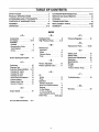
TABLE OF CONTENTS
SAFETY RULES ............................................................
2
CUSTOMER
PRODUCT SPECIFICATIONS
3
SERVICE AND ADJUSTMENTS ..................................
16
STORAGE ....................................................................
17
ACCESSORIES
......................................
AND ATTACHMENTS
CONTENTS OF HARDWARE
.......................... 5
PACK ..................................6
RESPONSIBILITIES
TROUBLESHOOTING
ASSEMBLY ....................................................................... 7-8
REPLACEMENT
OPERATION ................................................................
WARRANTY
9-13
.......................... _ 4-15
......................... _......................... 18
PARTS .........................................
19-29
.................................................................
29
INDEX
-AAccessories
-p-
m H --
...............
5
Air Cleaner .............
Assembly
Chet".,_Jist.................................
9,15
Hardware Pack .............
High Pressure Hose .......
6
8, 9
-B-
-M-
Replacement Parts ......
Agreement ..........................
Engine ...............................
Pressure Washer ................
3
15
14
Pump .........................
16
-N-C...............
16
15
16
15
14
t4
Replace Spark Plug ..............
Service Ait Cleaner. ...............
t5
15
-EEngine Speed ...............
No_le, Adjustable .........
No_le, Optional Turbo .....
10
11
!3
3,14
Changing Oil, engine ..............
Changing Oil, pump .................
Checking Oil Level .................
General Recommendations .....
Pressure Washer ..................
16
19-29
Maintenance
Before Starting the Engine .. _ 11
Cleaning Tips .............
Customer Responsibilities.
10
-R8
Removing from Carton ............... 7
Tools Required ................
7
Set Up .........................
7-8
Carburetor,
Pressure Regulator .........
-SSafety Latch ..............
Safety Rules ..............
Service and Adjustments o..
Siphoning ...............
Specifications .............
Storage
Engine...........................
Pressure Washer Pump .........
13
2
16
13
3
17
17
-T-
Oil
Engine ............................
Pump .............................
12
16
Operation
Detergent Application ...........
11
Know Your Pressure Washer ...o. 9
Stopping ..........................
To Start Engine ......................
ToTum on Washer .................
10
13
12
Using Adjustable Nozzle .......... 10
Order Parts ...........
back page
-GGun and Wand Assembly., ._ 8, 9
4
Troubleshooting ..........
18
-WWarranty .................
29
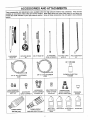
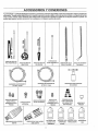
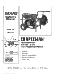
ACCESSORIES
AND ATTACHMENTS
These accessories and attachments were available when the high pressure washer was purchased,, They are also
available at most Sears retail outlets and service centers. Most Sears stores can order these items for you when you
provide the model number of your high pressure washer. Some of these accessories may not apply to your pressure
washer°
®
u
FLOOR/SIDING
BRUSH KIT
ROTATING BRUSH
KIT
18" STAINLESS
STEEL EXTENSION
ELECTRIC TURBO
NOZZLE
ACCESSORY
QUICK CONNECT
ACCESSORY
QUICK CONNECT
STARTER KIT
ANGLE EXTENSION
KIT
CHEMICAL INJECTION
FOAMER
3/8" I,,D, 50 It. EXTENSION
HOSE
1/4" ID., 25 ft. EXTENSION
HOSE
HIGH PRESSURE
HOSE QUICK. CONNECT KIT
UTILITY BRUSH KIT
HIGH PRESSURE
HOSE TO HOSE
COUPLING
GARDEN HOSE
QUICK CONNECT
WITH 2 ADAPTORS
PRESSURE
GAUGE
tC;
' TURBO NOZZLE
1800 PS! (max,)
TURBO NOZZLE
2200 AND 2500 PSI (max,)
MULTI-PURPOSE/HOUSE
WASH
DECK WASH
VEHiCLE/BOAT
WASH
DEGREASER
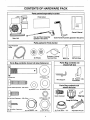
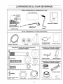
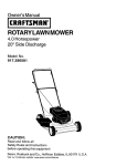
CONTENTS OF HARDWARE PACK
Parts packed separately
in carton
Parts Carton
m
!
Owner's Manual
Gun and Wand Assembly
(packed in flat carton)
Main Unit
Parts packed
Guide Handle Assembly (packed in flat carton)
In Parts Carton
High Pressure
Hose
Detegent Pickup
Tube and Filter'
(2) Wheels
!
Pads Bag contents
shown full size ,(fasteners)
_
':
MotQr Oit
(3)Parts Bags
Pads Bag contents not
shown full size
(2) Washers - M8
(2) Axle Pins
Wire Support
(2) Support
Assemblies
Leg
!l[ifiJliirlliiFllIl![fltiiJllr!!tlU
(2) Hex Head Capscrews
Parts Bag contents not
shown full size
- M8 x 40tT_
(2) Washers - #10
(2) Washers - M 12
0
Quick Connect
(6) Flange Nuts-M8
(2) Lock Washers - 5/8"
(2) 5/8" JAM Nuts
(2) Push Nuts - i/2"
Adjustable Nozzle
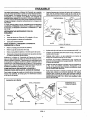
ASSEMBLY
Read these iv,sttuctions and Operator's Manual in its entirety before you attempt to assemble or operate your new
high pressure washer° Your high pressure washer has, for
the most part, been asserr_ed at the factory, except those
parts left unassembted. Before you can operate your new
high pressure washer, you must assemble the wheel kitand
property connect the high pressure hose.
HOW TO SET UP YOUR PRESSURE
TO INSTALL THE WHEEL KIT
Installing the wheel kit requires the tools listed, the guide
handle and items included in the parts carton°
°
IF YOU HAVE ANY PROBLEMS WITH THE ASSEMBLY
OF YOUR PRESSURE WASHER, PLEASE CALL THE
PRESSURE WASHER HELPLINE AT 1-800-_-3136.
TOOLS
REQUIRED
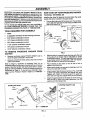
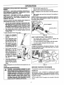
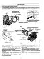
Prop up the engine end of the main unit. This will allow
you to slip each axle pin into the holes provided on the
side of the base (Fig 1).
JAM
FOR ASSEMBLY
o
Mallet
=
2 adjustable wrenches OR the following wrenches:
=,
5/16" (8mm) combination wrench
=
1/2" (13mm) combination wrench
-
5/8' (16mm) combination wrench
=
11/16" (18mm) combination wrench
=
7/8" (22ram) combination wrench
=
15/16" (24mm) combination wrench
TO REMOVE
CARTON
PRESSURE
LOGK1NASHER
JAM NUT
_L
REVERSE ANGLE
FLAT v
WASHER
FROM
FIG. 1
=,
Remove two boxes marked "PARTS INSIDE" and remove the parts contained in both boxes.
=
Remove unit with one hand under pump and one hand
under recoil starter.
Refer to Page 6, "Contents of Hardware Pack" for an
illustrated listingof all the items included with your pressure
washer, Become familiar with each piece before assembling the pressure washer,, Check all contents against the
illustrations on Page & If any parts are missing or damaged, call the Pressure Washer Helpline at 1-800-2223136,
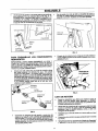
Installing the Handle
With the axle pin inserted inside the base, grip the end
of the axle pin as shown with an adjustable or 15/16"
combination wrench. This will keep axle from spinning
as you fasten axle to the base with a 5/8 lock washer,
a 5/8"-18 JAM nut, and an M12 flat washer..
o
Place wheels on the axles so the rib side of hub is
against mounting base.
=
Retain each wheel to its axle pin by tapping a push nut
onto end of axle with a mallet.
°
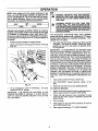
Attach support legs to base as shown in Fig, 2 with M8
x 20mm hex head capscrews and flange lock nuts,.
Tighten with 13mm or 1/2-inch wrench on each fastener.. Be sure legs are straight when you are tinished_
•
Attach the guide handle to the base as shown in Fig, 2
with two M8 x 40mm hex head capscrews, two M8
washers and two flange nuts.
Installing Support Legs
CAPSCREW
GUIDE
HANDLE
WASHER
\
CAPSC
WIRE SUPPORT
CAPSCREW
WASHER
_NUT
FIG. 2
ASSEMBLY
o
Remove male connector to inspect Intake Supply
Screen in water inlet for cleanliness and inspect Inlet
Screen on female connector. Reattach male connector
to water inlet and attach female connector to garden
hose.
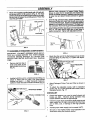
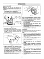
Attach wire support to guide handle with #10 self-dd!lin_! screws and #10 fiat washers (Fig° 3). The hose
mlnder should be to the left and gun holder to the d_tht.
Be sure loop of support is pointingupward. Place vinyl
cap onto gun holder.
o
Unravel high pressure hose, remove protective cap
from end of hose and check that threads are properly
covered with teflon tape° If tape is not properly applied,
reapply it so threads are fully covered. The tape seals
the connection from hose to gun and wand assembly°
.
Attach fitting with teflon tape to gun andwand assembly
(Fig° 6). You may want to spin gun or spin hose to
secure connection. Tighten with adjustable wrench.
WIRE SUPPORT
VINYL CAP
t
i /
/
FASTENERS
SUPPORT
FIG. 3
TO ASSEMBLE
REMAINING
COMPONENTS
IMPORTANT: YOU MUST ASSEMBLE WAND AND ATTACH ALL HOSES BEFORE YOU START ENGINE,.
STARTING
ENGINE WITHOUT
ALL HOSES CONNECTED AND WATER SUPPLIED WILL DAMAGE
PUMP°
FIG. 6
Attach the other end of the high pressure hose to high
pressure fitting on pump (Fig° 7). Tighten with adjustable wrench.
DETERGENT PICKUP TUBE
Remove cap from top of
pump and insert oil fill
cap included in parts bag
(Fig 4).
HIGH PRESSURE
HOSE
FIG. 4
Included with this unit is a Quick-Connect fitting you
attach to Water Inlet on pump. The quick-connect
includes two parts -- a Male Connector factory-insta!led on water inlet and a Female Connector (Fig. 5).
WATER INLET
FIG. 7
=
Attach Detergent Pickup Tube and Filter as shown in
Fig. 7.
=
To attach the adjustable nozzle, refer to Operation
section, Fig. 10o; to store optional turbo nozzle, refer to
Operation section, Fig. 17.
CHECKLIST
FEMALE CONNECTOR
*
Check that fasteners you used to install wheels and
handle are tight. Vibration during operation may
loosen fasteners that are not tight enough.
°
Check for proper hose connections (high pressure and
water supply) and for tight connections and that there
are no kinks, cuts, or damage to the high pressure
hose_
.
Provide proper water supply (not to exceed 140°F)_
,,
Be sure to read "Safety Rules" and "Operation"
tions before using the pressure washer.
MALE CONNECTOR
FIG. 5
sec-
OPERATION
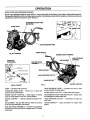
KNOW YOUR HIGH PRESSURE WASHER
READ THIS OWNER'S MANUAL AND SAFETY RULES BEFORE OPERATING YOUR HIGH PRESSURE WASHER.
Compare the illustrations with your high pressure washer to familiarize yourself with the locations of various controls and
adjustments. Save this manual for future reference,_
DETERGENT
AND RLTER
PICKUP TUBE
SPARK PLUG
HIGH PRESSURE HOSE
GUIDE HANDLE
OIL RLL OPENING
ENGINE ON/OFF CONTROL
CUP FOR WAND
PRESSURE
REGULATOR
GUN AND WAND
ASSEMBLY
INLET
WIRE SUPPORT t
FEMALE CONNECTOR
HIGH PRESSURE
€
GASOLINE
RECOIL STARTER
FIG. 8
QUICK-CONNECT
PUMP -- Develops high pressure,
PRESSURE REGULATOR -pressure of the outlet stream
CA!
Allows you to adjust the
HIGH PRESSURE HOSE -- Connect one end to water
pump and other to spray wand.
INTAKE SUPPLY FILTER -- Filters inlet water supply.
ENGINE ON-OFF CONTROL -- Sets engine in starting
mode for recoil starter; turns OFF running engine.
DETERGENT PICKUP TUBE AND FILTER --Mixes
and detergent in outlet water flow.
RECOIL STARTER -uallyo
Used for starting the engine man-
HIGH PRESSURE
sure hose.
OUTLET -- Connection
AIR CLEANER - Dry type filter element limits the amount
of dirt and dust that gets in the engine.
QUICK-CONNECT
supply.
--
GUN AND WAND ASSEMBLY-- Controls the application
of water onto cleaning surface with trigger device° Includes
safety latch.
Easy connection
water
for high pres-
for intake water
OPERATION
HOW TO USE YOUR
WASHER
IF YOU HAVE ANY PROBLEMS OPERATING YOUF..
PRESSURE WASHER, PLEASE CALL THE PRESSURE
WASHER HELPLINE AT 1-800-222-3136.
, _=." _,_;_:
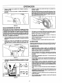
STOPPING YOUR PRESSURE WASHEF_
_;
First, move engine throttle lever to °OEW position (Fig
9).
" OPTIONAL TURBO NOZZLE
FIG. 11
FIG. 10
I
OFFr-]IDLE
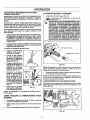
With the adjustable nozzle you can adjust the spray pattem
to be either high pressure or low pressure, You can also
adjust the spray so it is concentrated in a stream pattern or
expanded into a fan pattern Use this nozzle to apply
detergent
FAST
-J
_:sr _'_e..-_,-,
zz_ attachment torward when you wis!_:.
a_jusi the spray to low _ressure mode (Fig° 12). Pus_
the _ozzle backwa_ toachieve high pressure.
,,
"rwistir_g the nozzle adjusts the spray pattern from a
narrow stream to an expanded stream.
,,
You can also adjust the pressure by turning the pressure control knob (Fig., 13) to the desired pressure
setting. Turning this knob all the way clockwise produces the highest pressure. Do not unscrew the pressure control valve more than 3 tunis. It will come off
FIG. 9
Simply shutttng OFF engine will not release pressure in the system. Pull the trigger on the spray wand
assembly to relieve the pressure in the hose.
NOTE: A small amount of water will squirt out when you
release the pressure,
SPRAY NO77LES
Your high pressure washer comes equipped with an adjustable nozzle (Fig. 10). Attach nozzle as shown in Fig. 10
and HAND TIGHTEN the plastic knob Figure 11 shows the
optional turbo nozzle.
HOW 'TO USE ADJUSTABLE
NOZZLE
WARNING:
NEVER ADJUST SPRAY PATTERN
WHEN SPRAYING. NEVER PUT HANDS IN FRONT
OF SPRAY NOZZLE TO ADJUST SPRAY PATTERN,
}:.
t'-..
P_,JSH NOZZLE
NOZZLE IN HIGH
PRESSURE MODE
'- '
FORWARD
FIG.
13
•
'
gOF
._WIST NOZZLE TO
EXPAND SPRAY
LOW PRESSURE MODE AND DETERGENT APPLICATION
FIG_ 12
10
T_;IST NOZZLE
/ TO NARROW
SPRAY STEAM
OPERATION
DETERGENT APPUCATION
NOZ21JE
WITH ADJUSTABLE
IMPORTANT: USE SOAPS DESIGNED SPECIFICALLY
FOR PRESSURE WASHERS.
HOUSEHOLD DETERGENTS COULD DAMAGE THE PUMP°
IMPORTANT:
YOU MUST ATTACH ALL HOSES BEFORE YOU START THE ENGINE, STARTING THE ENGINE WITHOUT ALL THE HOSES CONNECTED WILL
DAMAGE THE PUMP.
Pressure washers are useful cteaning tools designed to
clean almost any surface in two easy steps+
=
o
o
Hook up water supply (Fig° 16).
o
Adjust nozzle to select high pressure mode_
NOTE:
mode_
o
Detergent will not flow when in the high pressure
Start washer and work from the top of the surface to
the bottom+
NOTE: The high pressure mode is most effective when the
tip of the wand is held between 8 inches to two feet from
the surface being cleaned.
The flint step involves applying an appropriate detert/€_etVentsolution to penetrate and loosen grime.
tergent is applied at low pressure to avoid
splashing, overspraying and was tp.. Leaveme .soButton
on surface for 3 to 5 minutes to allow somtion to WORK.
QUICK+CONNECT
WATER SUPPLY
The second step involves cleaning the surface you
have prepared with the pressure washer and then
rinsing it clean+
To apply detergent follow these steps:
,,
,,
o
o
•
Prepare your detergent
soluUon as required by
your job.
Place small filter of the
clear, detergent siphoning tube into the detergent container (Fig. 14)+
Set nozzle to tow pressure mode. Detergent is
not siphoned in the high
pressure mode (Fig° t2)..
FIGo 16
HOW TO USE OPTIONAL TURBO NOZZLE
o
The rotating turbo nozzle, in essence, expands the
area of the high pressure stream.
e
You cannot adjust the spray pattem with this nozzle,
o
You cannot apply detergent with this nozzle,,
STORING NOZZLES
FIG. 14
l
Start washer and apply
detergent to a dry' sur- INCREASE_
face, starting from the
bottom and working up.
You can adjust the concentration of detergent
by tuming the knob on
the detergent
injector
(Fig_ 15).
Turn knob clockwise or
remove siphon from bottle to stop flow of deterFIG. 15
gent in tow pressure
mode.
A holder for the nozzles is included on the base,+ You can
keep the adjustable nozzle in this holder (Fig. 17) or even
the optional turbo nozzle.
OPTIONAL TURBO
NOTE: Detergents are most effective when applied to a dr,/
surface+
PRESSURE
WASHING/RINSING
WARNING:
BE EXTREMELY
IF YOU
MUST USE PRESSURE
WAStiERCAREFUL
FROM LADDER,
SCAFFOLDING OR ANY OTHER RELATIVELY UNSTABLE LOCATION. PRESSURE IN A RUNNING
WASHER BUILDS IN THE WAND AS YOU CLIMB.
WHEN YOU PRESS THE TRIGGER, THE RECOIL
FROM THE INITIAL SPRAY COULD FORCE YOU
TO FALL, OR IF YOU ARE TOO CLOSE TO THE
CLEANING SURFACE, HIGH PRESSURE COULD
FORCE YOU OFF CLIMBING APPARATUS.
NOZZLE
FIG. 17
BEFORE
STARTING
THE ENGINE
To operate the engine you will need the following:
ENGINE OIL
IMPORTANT:
ANY ATTEMPT TO CRANK OR START
THE ENGINE BEFORE iT HAS BEEN PROPERLY SERVICED WITH THE RECOMMENDED OIL RESULTS IN AN
ENGINE FAILURE,
A 27 oz., bottle of SAE 30 weight oil is included in the parts
carton,,
OPERATION
NOTE: When adding oil to the engine crankcase in the
future, use only high quality detergent oil rated with API
service classification SF, SG or SH rated SAE 30 weight.
Use no special additives. Select the oil's viscosity grade
according to your expected operating temperature.
GAS
A
WARNING:
NEVER FILL FUEL TANK INDOORS.
NEVER RLL FUEL TANK WHEN ENGINE IS RUNNING OR HOT. DO NOT SMOKE WHEN FILLING
FUEL TANK.
a,
WARNING:
NEVER FILL FUEL TANK COMPLETELY FIJLL FILL TANK TO ABOUT 1/2" BELOWTHE BOTTOM OF FILLER NECKTO PROVIDE
SPACE FOR FUEL EXPANSION. WIPE AWAY ANY
FUEL SPILLAGE FROM ENGINE AND EQUIPMENT
BEFORE STARTING.
Although mutti-viscosity oils (5W30, 10W30, etc.) improve
starting in cold weather, these multi-viscosityoils will result
in increased oil consumption when used above 32°F.
Check your engine oil level more frequently to avoid possible damage from running low on oiloOil sump capacity is
20 ounces.
The manufacturer recommends fresh, clean, unleaded
regular automotive gasoline with a minimum of 77 octane
(Leaded regular grade is an acceptable substitute). Tank
capacity is 2 U,S. quarts.
•
Position pressure washer so engine is level.
*
.
Clean area around oil fill plug and remove oil fill plug
(Fig. 18)_.
Use clean fuel and store in approved, clean covered
containers_ Use clean fill funnets_ Never use "stale"
asoline left over from last season or gasoline stored
r long periods.
IMPORTANT:
IT IS IMPORTANT TO PREVENT GUM
DEPOSITS FROM FORMING IN ESSENTIAL FUEL SYSTEM PARTS SUCH AS THE CARBURETOR, FUEL FILTER, FUEL HOSE OR TANK DURING STORAGE. ALSO,
EXPERIENCE INDICATES THAT ALCOHOL-BLENDED
FUELS (CALLED GASOHOL OR USING ETHANOL OR
METHANOL) CAN ATTRACT MOISTURE WHICH LEADS
TO SEPARATION AND FORMATION OF ACIDS DURING
STORAGE. ACIDIC GAS CAN DAMAGE THE FUEL SYSTEM OF AN ENGINE WHILE IN STORAGE. TO AVOID
ENGINE PROBLEMS, THE FUEL SYSTEM SHOULD BE
EMPTIED
BEFORE STORAGE
OF 30 DAYS OR
LONGER. SEE "STORAGE" ON PAGE 17. NEVER USE
ENGINE OR CARBURETOR CLEANER PRODUCTS IN
THE FUEL TANK OR PERMANENT DAMAGE MAY OCCUR.
I_G. 18
°
Fill oil crankcase to point of overflowing. Oil sump
capacity is 20 U.S_ ounces..
,,
Clean area around fuel fill cap, remove cap.
.
Add "UNLEADED"
tank.
*
Install fuel cap and wipe up any spilled gasoline.
regular gasoline,
slowly, to fuel
TO TURN ON WASHER
IMPORTANT:
THE MOTOR OIL INCLUDED IN THE
CARTON CONTAINS 27 OUNCES. IT IS NOT NECESSARY TO USE THE ENTIRE AMOUNT OF OIL IN THE
OIL CONTAINER°
*
Attach one end of a garden hose to a cold water source=
Water supply should not exceed 140°F (55°C)_
=
Check that high pressure hose is attached to pump
outlet and that water supply is attached to pump inlet
(plastic fitting)_
Turn ONwater_
=
12
*
Press trigger on gun and wand assembly to force air
from high pressure hose.
=
Start engine according to "TO START ENGINE."
OPERATION
TO START
ENGINE
IMPORTANT:
DO NOT RUN PUMP WITHOUT THE
WATER SUPPLY CONNECTED AND TURNED ON. YOU
MUST FOLLOW THiS CAUTION OR THE PUMP WILL, BE
DAMAGED_
o
Press trigger on pressure washer wand to relieve high
pressure and/or purge the inlet hose of air°
o
Move engine control lever to CHOKE position (Fig. 19).
FIG. 21
NOTE: The engine is equipped with low oi! level shutdown
system. The engine will not start unless the oil crankcase
is filled to proper level. If engine shuts down during operation or you have difficulty starting the engine, check crankcase oil level and add oil if required°
IDLE
FAST
]
=
Once engine has started, place Safety Latch on spray
gun in OFF position_
,,
Press trigger on gun and wand assembly.
should spray out the nozzle.
=
Adjust no_le for correct pressure, spray angle. You
can also turn the pressure control knob to the desired
pressure setting_
o
Your pressure washer is ready to user
FIG. 19
o
Move throttle control to FAST position.
o
Press tdgger and releaseto relieve pressure in system.
@
Adjust safety latch to the ON position. This disables
the trigger so you cannot inadvertently actuate a high
pressure spray (Fig° 20)°
SIPHONING
We recommend that you DO NOT siphon your water supplyoConnect only to household water supply.
TIPS
=
Initially clean an area and then check the surface for
damage, if no damage is found, you can assume it is
okay to continue cleaning Detergents work best when
applied to dry surface,
,,
For most effective cleaning, keep spray nozzle between 8 to 24 inches of cleaning surface.
o
Allow the detergent to soak in between 3-5 minutes
before washing and rinsing
=
For cleaning, start at lower portion of area to be washed
and work upward, using long, even overlapping
strokes.
=
For rinsing, push the nozzle sleeve to high pressure
and wait for detergent to clear. Start at the top of area
to be rinsed, working down with the same action as for
cleaning..
o
Never use the garden hose inlet to siphon detergent or
FIG. 20
•
°
°
Water
Grasp the engine starter recoil handle and pul! back
slowly until you feel some resistance. Then pull rope
rapidly to overcome compression, prevent kickback
and start engine° Let rope return slowly (Fig. 21)_
wax,
When engine starts, move choke lever to "RUN" position and throttle control to "FAST" position. If engine
fails to start, move choke lever to "RUN" position and
pull starter rope (max. 2 pulls)_
if engine fails to start, repeat the process up to three
times, then check the Troubleshooting Chart.
13
°
If you get the spray nozzle too close, especially using
high pressure mode, you may damage the cleaning
surface_
°
if you have the spray nozzle too far away, the cleaning
will not be as effective.
,_
Do not get closer than 6 inches when cleaning automo bite tires.
CUSTOMER
, i i
ii
RESPONSiBiLiTiES
,,Jiiiiiiil,,,,
Jl,i
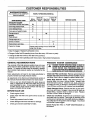
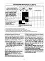
MAINTENANCE SCHEDULE
HOURLY OPERATING
FILL IN DATES AS YOU COMPLETE
REGULAR SERVICE
Every25
Before Hoursor
Each Use .......
Yearly
MAINTENANCE TASK ....
PRESSURE WASHER
Check/dean inletfiller and screen _
Check highpressurehose. ,, ,,,,,,......
INTERVAL
AfterFirst
50 Hours
Every100
Hoursor
Yearly
SERVICE DATES
Xt ..................
X
Check detergenthose.
X
Check gunand wand for leaks.
X
Change pumpoil
ENGINE
Check oil level.
X:I:
........
X*
............
Serviceair cleaner.
Preparefor storage=
............... i,,
X
Change engineoil. _
Replace/dean spark plug.
;
r
........
X"°
_
X
Prepare unitfor storageif it is to remainidle
Jlongerthan30 days
1"Clean if clogged.. Replace if perforated or torn.
:1:Change oil after first 50 operating hours, then after every 100 hours or yearly.
Change oil after first 5 hours, then after evePj 25 hours.
* Change sooner=when operating under heavy load or high ambient temperature.
GENERAL
RECOMMENDATIONS
PRESSURE
,_
The warranty of the high pressure washer does not cover
items that have been subjected to operator abuse or negligence_ To receive full value from the warranty, operator
must maintain high pressure washer as instructed in this
manual,.
Some adjustments will need to be made pefiodicaUy to
properly maintain your' high pressure washer,
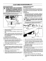
Check Detergent Hose: Examine the filter on the detergent hose and clean if clogged. Hose should fit tightly on
barbed fitting. Examine hose for leaks or tears. Replace
the filter or hose if either is damaged_
EACH USE
Check engine oil level.
°
Check water inlet filter and quick-connect screen for
damage...
°
Check high pressure hose for leaks_
°
Check detergent inlet hose and filter for damager
,,
Check gun and wand assembly for leaks_
DANGER: WATER SPRAYING FROM A LEAK iS t
CAPABLE OF INJECTING MATERIAL INTO SKIN. I
NEVER REPAIR HIGH PRESSURE HOSE. RE-I
PLACE WITH HOSE THAT MEETS MINIMUM PRES- I
SURE RATING OF YOUR PRESSURE WASHER.
j
Check High Pressure Hose: High pressure hose can
develop leaks from wear', kinking, abuse., Inspect hose
each time before using it, Check for cuts, leaks, abrasions
or bulging of cover, or damage or movement of coupfings_
If any of these conditions exist, replace hose immediately°
Once a year you should replace the spark plug and
clean or replace the air falter and check the gun and
wand assembly for wear_ A new spark plug and clean
air filter assure proper fuel-air mixture and help your
engine run better and last longer..
,,
MAINTENANCE
Check Inlet Filter and Screen: Remove quick-correct and
examine inletscreen onthe femaleo0nnectorandfilteror1pump
inlet fit_ng, Clean if either is dogged or replace if either is tom.
All adjustments in the Service and Adjustments section of
this manual should be made at least once each season.
BEFORE
WASHER
Check Gun and Wand: Examine hose connection to gun
and make sure it is secure_ Test trigger by pressing it and
making sure it springs back into place when you release it.
Put safety latch in ON position and test trigger° You should
not be able to press trigger.
Check Pump Oil: Refer to PUMP MAINTENANCE
information.,
]4
for
CUSTOMER RESPONSNBHUTY
ENGINE MAINTENANCE
PUMP MAINTENANCE
CHECKING OIL LEVEL
THE PUMP. WITHOUT THE PROPER TECHNIQUE,
I:
ATTEMPTING TO DISASSEMBLE PUMP MAY
CAUSE PERSONAL INJURY. FOR SERVICE, CONWARNING:
SULT A SEARS
DO NOT
AUTHORIZED
ATTEMPT TO
SERVICE
DISASSEMBLE
CENTER
OR CONTACT YOUR PLACE OF PURCHASE.
See "PREPARATION BEFORE USE" for information on
checking oil level Oil level should be checked priorto each
use or at least ever]/5 hours of operation,. Keep oil level
maintained..
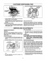
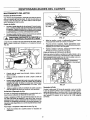
CHANGING OIL
Pump Oih Change pump oil after first 50 hours of operation. To change pump oil, follows these steps:
o
Change oil after first 5 hours of operation,. Change oil
every 25 hours thereafter,. If you are using your pres*
sure washer under extremely dirty or dusty conditions,
or in extremely hot weather, change oil more often.
Place a proper container beneath the pump (Fig, 22).
Change oil while engine is still warm from running, as
follows:
O
/_
FROM SPARK PLUG AND KEEP IT AWAY FROM
CAUTION: DISCONNECT SPARK PLUG WIRE 1
SPARK PLUG.
Clean area around oil drain plug, remove plug and drain
oil completely into a suitable container (Fig.. 23).
°
OIL D_RAIN PLUG
FOR PUMP
FIG. 22
o
Remove the Oil Fill Plug on bottom of pump and drain
oil into the container.
=
When oil has drained completely,
plugo
o
Remove pump's oil fill plug, insert funnel and add
recommended SAE 80W-90 oil until level reaches full
mark on gauge located on side of the pump Capacity
is 9 ounces (260ml)_
Reinstall the pump's oil fill plug.
=
reinstall oil drain
FIG. 23
Purge Pump of Air and Containments:
To remove the air from the pump, follow these steps:
o
When all oil has drained, install and tighten oil plug..
o
Set up the pressure washer as described in the ASSEMBLY section and connect the water supply.
=
Clean area around oil fill plug and remove oil fill plug..
o
Remove the nozzle attachment from the gun°
°
Fill engine crankcase with recommended oil until oil
level is at point of overflowing. About 20 ounces is
required, POUR SLOWLY.
°
When engine crankcase is filled to proper level, install
and tighten oil fill plug.
o
Pull the trigger on the gun and hold
To remove the containments from the pump, follow these
steps:
=
Set up the pressure washer as described in the ASSEMBLY section, connect the water supply and start
the engine according to instructions in the OPERATION section.
=
Remove the nozzle attachment from the gun_
=
Pull the trigger on the gun and holdo
o
When the water supply is steady and constant, you may
refasten the nozzle attachment and start the pump.
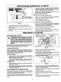
SERVICE AIR CLEANER
Your engine will not run properly and may be damaged if
you run it using a dirty air cleaner.
Clean or replace the air cleaner paper filter once every 100
hours of operation or once a year, whichever comes first.
Clean or replace more often if operating under dusty or dirty
conditions. Replacements are available at your local Sears
Authorized Service Center.
To clean or replace air cleaner (Fig. 24 on Page t6):
=
15
Loosen cover screws (these need not be removed) and
remove cover. Thoroughly clean inside of base and
cover.
CUSTOMER
RESPONSIBiLiTiES
Keep dirt and combustible
e
debris
off of muffler
area,
CLEAN OUT:
CHAFF AND
DIRT
AIR CLEANER
E[
FIG. 24
o
Service cartridge by tapping gently on a flat surface.
Replace if dirty° Do not oil cartridge.
o
Insert cartridge (new or used) and reassemble cover to
base as it was removed before. Tighten cover screws
securely.
FIG. 25
REPLACE SPARK PLUG
Change the spark plug every 100 hours of operation or
once each year, whichever comes first. This will help
engine to start easier and run better. See pressure washer
specifications for the type of spark plug you need,. Spark
plug gap is 0.030 inch (0.76ram).
CLEAN COOLING SYSTEM
=
Clean dirt or chaff from finger' _luard or rotating screen
every 8 hours to prevent engine damage caused by
overheating (Fig.. 25)°
SERVICE AND ADJUSTMENTS
FINAL ADJUSTMENT
ENGINE ADJUSTMENTS
Carburetor=
Differences in fuel, temperature, altitude or load may require minor carburetor' adjustment. Air cleaner and air
cleaner cover must be assembled to carburetor before
starting engine.
o
Start engine and let it warm up for at least five minutes_
o
With engine running, turn NEEDLE VALVE inward
(clocle_ise - lean mixture) until engine just starts to
slow.
ENGINE
INmAL ADJUSTMENT
=
°
_"
SPEED
ERNOR WHICH IS FACTORY SET FOR PROPER
ENGINE
SPEED.
OVERSPEEDING
ENGINE
WARNING:
ABOVE
FACTORY
NEVER HIGH
TAMPER
SPEED
WITH
SETTING
ENGINE
CAN
GOVBE
DANGEROUS.
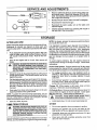
Gently turn NEEDLE VALVE (Fig,, 26) clockwise until it
just closes_Valve may be damaged by turning it inward
too far..
i
Next open NEEDLE VALVE I-1/2 turns counterclock-.
NOZZLE
IDLE SPEED
ADJUSTING SCREW
MAINTENANCE
If the nozzle becomes restricted or clogged with foreign
materials, such as dirt, excessive pump pressure may
develop. A partially clogged nozzle can cause a pulsing
sensation during use° This generally is not a pump related
problem, but rather a clogged or partially restricted nozzle,
THROTTLE
STOP
If the nozzle becomes clogged or partially restricted, immediately clean the nozzle with the kit included with your
pressure washer by following these instructions:
\
i
THROTTLE
NEEDLE
VALVE
,
Shut off the engine and turn off the water supply,
°
Separate the wand from the gun.
°
Remove nozzle from the end of the wand using a 2mm
or 5/64 allen wrench (like the one included in the kit).
,,
Use ttle wire included in the kit (Fig° 26 on Page 17) or
a small paper clip to free the foreign materials clogging
or restricting the nozzle..
FIG. 26
wise,.
This initial adjustment will permit the engine to be
started and warmed up
]6
SERVICE AND ADJUSTMENTS
O
Remove additional debris by back flushing water supply through wand. Back flush between 30 to 60 seconds,. Turn wand to stream spray and move nozzle from
low to high while flushing.
0
Reinstall nozzle into the wand,, DO NOT overtighten,
0
Reconnect the wand to the gun
o
Reconnect the water supply, turn on the water, and
start the engine..
Test the pressure washer by operating with nozzle in
the high and in the low position.
FIG. 26
STORAGE
AFTER EACH USE
Water should not remain in the unit for long periods of time..
Sediments of minerals can deposit on pump parts and
"freeze" pump action. Follow these procedures after every
use:
Flush detergent hose by placing, the injector filter into
a pail of clear water while running Pressure Washer
with nozzle in low pressure mode° Flush for five minutes,,
Shut off the engine and let it cool, then remove awl
hoses.
.A
CAUTION;
BE SUREBEFORE
THE THROTTLE
LEVER IS IN
"STOP"
POSITION
YOU CONTINUE.
IF
YOU START THE ENGINE WITHOUT THE PROPER
WATER SUPPLY CONNECTED, YOU CAN DAMAGE THE PUMP.
o
Empty the pump of all pumped liquids by pulling recoil
handle about 6 times, This should remove most of the
liquid in the pump.
o
Coil the high pressure hose and inspect it for damage.
Cuts in the hose or fraying of it could result in leaks and
loss of pressure° Should any damage be found, replace
the hose. DO NOT attempt to repair a damaged hose
and use it. Replace the hose with the genuine Craftsman part_
Drain water from hose and properly hang it on the wire
support provided on the guide handle,
,,
NOTE: As always, prepare the pressure washer pump as
you would after each use_
It is important to prevent gum deposits from forming in
essential fuel system parts such as the carburetor, fuel
filter, fuel hose or tank during storage° Also, experience
indicates that alcohol..blended fuels (called "gasohol" or
using ethanol or methanol) can attract moisture which leads
to separation and formation of acids during storage. Acidic
gas can damage the fuel system of an engine while in
storage
To avoid engine problems, the fuel system should be
emptied before storage of 30 days or longer. Follow these
instructions:
Protect Fuel System: Engines stored over 30 days need
to be protected or drained of fuel to prevent gum deposits
from forming in fuel system or on essential carburetor parts°
For engi,_e protection use a fuel stabilizer (such as
STA-BIL'_')oMix stabilizer with fuel in fuel tank and run
engine for short time to circulate stabilizer through
carburetor.
,_
If you did use "gasohot", run engine until engine stops
from lack of fuelo Make sure you have water supply to
pump inlet connected and turned ON,.
Change Oil: While engine is still warm, drain oil from
crankcase. Refill with recommended grade°
Oil Cylinder Bore: Remove spark plug and pour about 1/2
ounce (15ml) of engine oil into the cylinder. Cover spark
plug hole with rag_ Crank slowly to distribute oil.
NOTE: To protectthe unitfrom freezing temperatures,you can
draw windshieldwasherfluid intothepumpby pouringthe washer
fluid into a 3-foot sectionof garden hose connectedto the inlet
adapterand pullingthe recoilhandle twice..
°
,,
i _
°
Store in a clean, dry area°
CAUTION,
SPARKPLUG I
HOLE
WHENAVOIDSPRAYFROM
CRANKING ENGINE SLOWLY.
Install spark plugo Do not connect spark plug wire.
OTHER
LONG TERM STORAGE
WARNING:
NEVER
ENGINEPOORLY
WITH FUEL
IN
TANK
INDOORS
ORSTORE
IN ENCLOSED,
VENTILATED AREAS WHERE FUMES MAY REACH AN
OPEN FLAME, SPARK OR PILOT LIGHT AS ON A
FURNACE, WATER HEATER, CLOTHES DRYER
OR OTHER GAS APPLIANCE.
If you do not plan to use the Pressure Washer for more than
30 days, you must prepare the engine for long term storage..
17
,_
Do not store gasoline from one season to another.
o
Replace your gasoline can if your can starts to rusL
Rust and/or dirt in your gasoline will cause problems°
=
If possible, store your unit indoors and cover it to give
protection from dust and dirt..
o
Cover your unit with a suitable protective cover that
does not retain moisture°
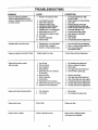
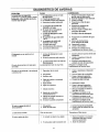
TROUBLESHOOTING
PROBLEM
Pump hasfollowingp_oblems:
failure to pn_uce pressure,erratic
pressure,chattering,loss of pressure,
lowwater volume.
CAUSE
CORRECTION
1. Nozzle in low pressure mode,
2_ Low regulator pressure
3. Water inlet is blocked.
4o Inadequate water supply
5o inlet hose is kinked or leaking
6. Clogged inlet hose strainer.
7_ Detergent line is not submerged.
8. Water supply is over t40°F.
9_ Outlet hose is blocked or leaks.
10, Gun leaks.,
11_ Nozzle is obstructed.
12. Pump isfaulty°
1,, Pull nozzle backwardfor high
pressuremode.
2_ Adjustrogutatortodesiredsetting,
3. Clear inlet
4. Provideadequate waterflow.
5o Straighteninlethose,patch leak.
6o Check and clean Inlet hose strainer.
7. Submergedetergent line.
8. Providecoolerwater supply.
9. Clear blocks inoutlethose_
10 Replace gun.
11_ Clear _],
12, ContactSears ServiceDepartment,
Detergentfails to mix with spray,
1. Detergentline Is not submerged.
2. Chemical filter is clogged
3. Nozzle is in highpressuremode
1. Insert chemical line into detergent,.
2, Clean or replace filter/deteq;tent line.
& Push nozzle forward for
low pressure mode,
Engine runs good at no-load but "bogs
Enginespeed is too slowo
Contact Sears Service DepadrnenL
Enginewillnot start;or starts
and runsrough
1. Low oil level
1. Fill crankcase to proper level.
2, Clean or replace air cleaner.
3. Fill fuel tank.
2. Dirty air cleaner
3. Out of gasoline.
4. Stale gasoline,,
5,_ Spark plug wire not connected
to spark plug
6_ Bad spark plug.
7,, Water in gasotine_
4, Drain gas tank; fill with fresh fuel.
5. Connect wire to spark plug.
80vemhoking
9 Excessively rich fuel mixture.
10o Intake valve stuck open or closed.
11o Engine has lost compression.
6,,
7,,
8
9
10o
11.
Engine shuts down during operation
1,
2.
1. Fill fuel tank.
2o Fill crankcase to properlevel.
Engine lacks power,_
Dirty air filter.
Replace air filter,
Engine "hunts" or falters.
Choke is openedtoo soon.,
Move choke to halfway posffion
until engine runs smoolhly_
Out of gasoline,,
Low oil level,.
18
Replace spark plug.
Drain gas tank; fill with fresh fuel.
Open choke full'>,and crank engine_
Contact Sears Service Department.
Contact Sears Service Department,
Contact Sears Service Department,
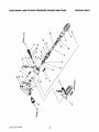
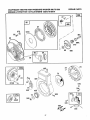
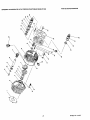
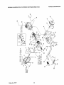
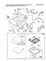
CRAFTSMAN
1800 PSi HIGH PRESSURE
WASHER
580.751500
REPAIR
PARTS
\
\
\,
N
/
L
\
Parts List for this drawing and for drawing on Page 20
can be found on Page 21.
19
Drawing No,, 95087
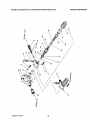
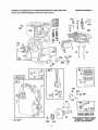
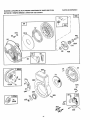
CRAFTSMAN
1800 PSi HIGH PRESSURE
WASHER
580.751500
REPAIR
.<
!
\
Drawing
No, 95087
20
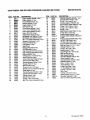
PARTS
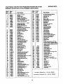
CRAFTSMAN
ITEM
1
PART NO.
9.3871
2
3
4
S
6
7
8
9
10
11
12
13
!4
15
16
17
18
19
96185
S6437
93869
93790
95386
95217
964O0
92479
93873
40945
94404
93680
93668
93667
96015
20
95454
2t
22
23
24
25
26
27
28
29
3O
31
32
3.3
34
35
36
37
38
39
95895
96O52
955O4
95503
96005
95896
95531
93652
95416
944O2
93873
93678
93645
93644
95`320
96525
95382
93722
93874
1800 PSi HiGH PRESSURE
WASHER
DESCRIPTION
580.751500
ITEM
PART NO.
40
41
42
43
44
45
46
47
48
49
50
51
95373
95367
95.372
95378
95377
93788
93787
95376
95374
95375
95365
95364-A
52
53
54
55
56
57
58
59
60
61
62
63
64
65
66
68
70
71
72
73
74
75
76
77
78
95381-A
96137
93723
95216
95369
95368
95370
95363
96069
95506
95453
57163
95371
95380
94738
95366
95434
94944
94284
93876
95379
93656
93657
95212-A
46580
Engine Adaptor Gasket (1 req.)
Engine Adaptor (1 req_)
Thrust Ball Bearing (1 mq_)
Washer Retainer (1 req.)
Engine Adaptor (1 req_)
Axial Cam (1 req.)
Thrust Roller Bearing (t req.,)
114 x 119 x 2o60_ring (1 mq,)
Piston Spring Retainer (3 req,)
Piston, D15 S So (3 req)
Piston Retum Spring (3 req_)
M8 Ribbed Lock Washer (10 req.)
M6 Ribbed Lock Washer (9 req.)
M6 x 1_0x 20ram Capscmw (7 req)
Aluminun Crankcase (1 req)
Pistion Oil Seal (3 req,)
Pilot Spacer (3 req)
Seat (3 req_)
Beadng Ring Seal (3 req)
Oil Fi!l/Breather (1 reqo)
High Pressure Port Tower (3 req)
High Pressure Seal [black] (3 reqo)
Back-up Ring (1 req.)
O-Ring 2°62 x 1712mm (6 req.)
Valve Check Kit (6 req)
Check Valve Seat Support (3 req,,)
5/16"-24 x 3/4" Bolt (4 req,)
Thermal By-pass Spring (t req,)
By-pass Piston (1 req,,)
Spacer Plate (1 req.)
O-dng 4,,5 x 8 x 1.8 (2 req)
M5-0.,8 x 20 Truss Head Bolt (2 req)
Head Gasket (1 req.)
Thermal By-pass Actuator (1 req,)
Garden Hose Connector (! req,)
Cylinder Head (1 mq ,)
Spindle Seat (1 req)
O_Ring, 1°78 x 172 (2 req)
M8-1 .,25 x 75mm Capscrew (6 req.)
21
REPAIR
PARTS
DESCRIPTION
Unk_ader Assembly Spindle (1 req)
Unloader Piston Guide (1 req.)
O-nng 1.78 x 14ram (1 reqo)
Chemical Injector Fitting (1 req.)
High Pressure Ob_et Adaptor (1 reqo)
O_dng 1.78 x 12Amm (1 mq)
O-ring 1.78x 156mm (1 req_)
spring(1 req,)
High Pressure Outlet Piston (I re(] )
O-ring, #2A x 4.3 (1 req.)
Pressure Adjust Spring (1 req)
Pressure Adjust Adaptor with groove
(1 mq.)
Pressure Adjust Handle [red] (1 reqo)
1/8" NPT Pipe Plug (1 req,)
=O" Ring 2,,6 x 202 (1 req,)
Pressure Relief Valve Body (1 req)
Back-up O-ring 11 x 12A (1 reqo)
Unloader Piston (1 req.)
O-ring 1,78 x 7.65 (1 req)
Spring Support (1 req_)
Quad-Ring 0.09 x 1.06" (3 req.)
Beck-up Ring (3 req.)
Sight Gauge Assembly
3/8" NPT Magnetic Plug (1 req)
Piston Support (1 req.)
Chemical Injector Spring (1 req.)
Bellevilte Washer (1 req.)
M18 x 1_0Nut (1 req)
Thrust Washer (1 req )
Piston Pivot Shoe (1 req)
"C" Ring Retainer (3 req_)
O-Ring 1_78 x 29 (1 req)
Ball (1 req.)
O-Ring 1.78 x 607 (1 req)
Back-up Ring 1o24x 67 (1 mq.)
Unloader Assembly (1 re<!)
M6-10 x 45ram Cap.screw (2 req.)
Drawing No,, 95087
:
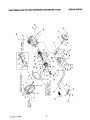
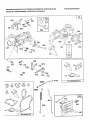
CRAFTSMAN
1800 PSI HIGH PRESSURE
WASHER
\
\
"'i
.....
@
_r. ' .....
xt
"
Drawing
No. 94720
i
22
580.751500
REPAIR
PARTS
CRAFTSMAN
ITEM
1
2
3
4
5
6
7
8
9
10
11
12
13
14
15
16
18
19
20
21
22
23
24
25
26
27
28
29
30
31
32
33
34
35
36
37
38
39
40
41
42
44
45
46
47
48
49
50
51
52
53
54
55
56
57
58
59
1800 PSi HIGH PRESSURE
PART NO.
95998
95319B
51767
96016
95456
93790
93869
95437
95435
95434
95524
57108
95531
96430(3
93871
92479
39414
95902
75402
91094
_46
25391
93278
39253
52858
92235
91092
87841
57821
50190
91093
92067
95908
96633
86292
77584
96168
95587B
91630
95567
93873
92659
658.52
94944
_47!
91842A
23365
88977
91841
24679
95454
40945
93873
96581C
93723
40945
49808
WASHER
580.751500
REPAIR
PARTS
DESCRIPTION
5 HP BRIGGS & STRATTON ENGINE (1 REQ)
2.5 GPM PUMP (1 REQ.)
M6-1.0 x 45ram CAPSCREW (2 REQ.)
QUICK.CONNECT, FEMALE (1 REQ.)
QUICK-CONNECT, MALE (1 REQ.)
O-RING, 2.6x 114 (1 REQ.)
THRUST BEARING (1 REQ.)
2.5 PGM AXIAL CAM (1 REQ.)
ENGINE ADAPTOR SHAFT (1 REQo)
THRUST WASHER (1 REQ.)
WASHER RETAINER (1 REQ.)
BEARING (1 REQ°) ....
5/16"-24 x 3/4" SL)Ut',_= HEAD BOLT (4 REQ,)
ENGINE ADAPTOR (1 REQ.)
ENGINE ADAPTOR GASKET (1 REQ.)
M8 RIBBED LOCK WASHER (4 REQ.)
M8-1,25 x 35mm HEX HEAD CAPSCREW (4 REQ,)
MOUNTING BASE (1 REQ,)
1/2 dia, PUSH NUT (2 REQ.)
2-I/4" x 8" WHEEL (2 REQ.)
5/8" LOCK WASHER (2 REQ_)
JAM NUT (2 REQ,)
WHEEL AXLE (2 REQ.)
M8-1,25 x 20ram HEX HEAD CAPSCREW (6 REQ)
M8-1.25 FLANGE NUT (12 REQ,)
RUBBER GROMMET (1 REQ,)
SUPPORT LEG (2 REQ.)
M8-1.25 x 40mm HE
SCREW (2 REQ,)
M8 x 25 FLAT WASHER (2 REQ,)
GUIDE HANDLE (1 REQ)
VINYL CAP (1 RETD,)
GUN AND HOSE HOLDER (1 REQ,)
#10 FLAT WASHER (2 REQ)
#10 SELF-DRILLING SCR:_EW(3 REQo)
HANDLE GRIP (1 REQo)
CHEMICAL INJECTOR HOSE(1 REQ)
ADJUSTABLE NOZZLE (1 REQo)
3/8 LD, x 25 FT, HOSE ASSEMBLY (1 REQ)
GUN AND WAND ASSEMBLY (1 REQ)
M6 RIBBED LOCK WASHER (6 REQo)
REPLACEMENT NOZZLE [RED] (1 REQ)
SPR NG
CUP1REQ.
PISTON
P,VO1
(SHOE
Ca
REe. rnb
Iy] ( 2REQ
#8-32 NU[!ow oil shut down ass
_)
LOW OIL SHUTDOWN WIRE (1 REQ.)
#8 SHAKEPROOF LOCKWASHER (1 REQ.)
LOW O!L SHUTDOWN (1 REQ,)
LOW OIL SHUTDOWN GASKET (1 REQ.)
#10-32 x 3/4" TAPTtTE SCREW (2 REQ.)
OIL CAP/BREATHER (1 REQ.)
M6-1.0 x 20ram SOCKET HEAD CAPSCREW (3 REQ.)
M6 RIBBED LOCK WASHER (3 REQo)
UNLOADER ASSEMBLY (1 REQ.)
SPINDLE SEAT"O RING (1 REQ.)
M6-1,0 x 20ram SOCKET HEAD SCREW (4 REQo)
M12 FLAT WASHER (2 REQ)
23
Drawling No. 94720
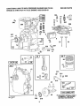
CRAFTSMAN
1800 PSI HIGH PRESSURE WASHER 580.751500
BRIGGS & STRATTON
4-CYCLE ENGINE 133212-0159-01
REPAIR
PARTS
13A
635
337
346
306
308
5
357
10
!
741
N!
11
15
26
I 2o1.1
,......
0
12
615
616
45
i
11o19LABELKITI
\" _
220
219
24
_ t
N,O
"h"REQUIRES SPECIAL TOOLS
TO INSTALL. SEE REPAIR
INSTRUCTION MANUAL.
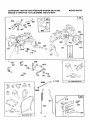
CRAFTSMAN
1800 PSi HIGH PRESSURE WASHER 580.751500
BRIGGS & STRATTON 4-CYCLE ENGINE 133212-0159-01
634
REPAIR
PARTS
97
394
4
392
127
187
127A
149
433
!__!_\
_
52 _
435
611
256
124[153
_1012
217
52!_ _
542
779
414
153
394_
191 _
J
414A
3
,__--_
978
!
121 CARBURETOR
KIT
163
9
(9
52
7
216
201
232
621
467
35B GASKET
SET
25
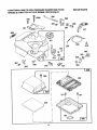
CRAFTSMAN 1800 PSI HIGH PRESSURE WASHER 580.751500
BRIGGS & STRATTON 4-CYCLE ENGINE 133212-0159-01
190
190A
208
REPAIR
PARTS
280
®_
,_.__o o
206
2O7'
271
2O9
268
_,
270
269
985
223
520
353
(_
_
354
969
967
971
163
L_.....
_J
26
] 966......
REPAIR
CRAFTSMAN
1800 PSg HiGH PRESSURE WASHER 580.751500
BRIGGS & STRATTON 4-CYCLE ENGINE 133212..0159-01
57
PARTS
I
,)
1016
/
55
461
Y
69A
515
69
456
59
23
24
305
0
73
81
613A
304
670
t
©
334
346
......1676_346A
455
8_
75
332 (_
335
356
27
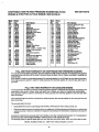
REPAIR PARTS
CRAFTSMAN
1800 PSI HIGH PRESSURE WASHER 580.751500
BRIGGS & STRATTON
4-CYCLE ENGINE 133212-0159-01
Part
I0.
I No.
495133
*299819
214040
"272157
294178
'27459
94621
68578
"27O080
94221
94733
94679
94387
495648
1
11
12
13
13A
14
lS
16
17
18
19
21
24
26
27
28
37
48
41
45
46
,
494874
495641
495660
%95387
66768
94682
267229
222698
393819
399687
26026
2969O9
299430
221890
94745
262464
281044
268552
262750
222443
93312
491 442
280642
212733
• $_t935
55
56
57
95
_A
75
81
108
118
t21
124
I_A
149
153
464846
493824
262594
280406
395892
393152
94686
280973
224322
224633
224061
222263
495426
93499
223793
49OO48
491177
231533
495606
94616
226352
223789
26336
268575
490569
93527
Part Name
Cylinder Assembly
Oil Seal
Cylinder Itead
Cylinder Head Gasket
Breather - Valve Chamber
Valve Cover Gasket
Screw - Breather Mounting Sam
Breather Tube Grommt
Cylinder Head Screw -- 2_3/32"
Cylinder Head Stud
Cylinder Head Screw
Oil Drain Plug (magnetic)
Cmrd_simft
NOTE: To replace crard_ahaft pin,
order Part No. 230978
Ball Beadng (PTO side)
Crankcase Cover Assembly
Bushing -- oil Seal
Oil Se ed
Oil Filler Plug
t-lax i-kind Screw
Flywheel
Flywheel Key
Piston Assembly
Ring Set
Pleton Pin Lock
Platen Pin Assembly
Connecting Rod Assembly
Connecting Rod Dipper
Connecting Rod Screw
Exl_ua! Valve
intake Valve
intake Valve Spring
Exhaust Vedve Spdng
Rywhsel Guard
Valve Spring Retainer
Retatnor Valve
Valve Tappet
Cam Gear
Carburetor Mounting Gasket
Rewind Starting Housing
Rewind Starter Pulley
Rewind Starter Swing
RewirKI Starter Rope (cut to length
Starter Handle Insert
Rewind Starter Handle
Housing Mounting Screw
Washer
Washer
Rotating Screen
Flywheel Washer
Screw Lock
Carburetor Assembly
ThretUe_Velvo-to-Sha ft Screw
Carburetor ThretUa
Throttle Shaft and Lovm"
Choke Valve Group
Needle Valve
Carburetor Kit
Flex Head Screw
Welch Plug
Welch Plug (Mixing Chamber)
Needle Valve Spdng
Throttle Adjustment Spring
Screw end Collar
Round Head Screw 5-40 x 5/8"
F_eL_ Part
_1o. No.
163
180
181
187
190
190A
191
Z01
Z02
203
2O4
Z05
Z06
Z07
298
2O9
216
217
219
22O
222
223
224
227
23O
232
256
265
267
268
*271935
495405
404556
231068
94712
94077
¥272489
26228O
262270
266720
222962
231520
94081
26855
262323
262282
262359
262281
391737
221551
490549
223455
93491
490374
222450
262310
223813
221535
93496
66968
269
27O
271
280
300A
304
305
305
306
332
333
334
335
337
346
346A
353
354
356
356
363
373
392
394
26O99
63426
29O568
223798
393615
495795
94619
22482O
224738
92284
397358
93613
93414
492167
9468O
93705
92791
9O576
3988O8
495603
19069
92967
262328
t272538
Part Name
Air Cleenor Mounting GHked
Fuel Tank Assembly
Fuel Tank Cap
Fuel Pipe
Screw - S_m
Screw- Sam
Fuel Tank Mo*.mUng Gasket
Govem_,r Unk
Thmttia Link
Bell Crank
Control Lover Bushlng
Shoulder Screw
StopNut
Control Rod Spdng
SpeedControlROd
Governor Spdng
Choke Mink
Choke Spdng
Governor Gear
TnPJs t Washer
Control Brecka!
Governor Control Lever
Governor Control Lever Rivet
GovernorLeverA_embly
Governor Lever Washer
Return Spdng
Bell Crank
Casing Clamp
Screw
Control Wire Casing N 48= long
ff longer casing Is needed, specify
lenght in Inches; if shortor casing
needed, order NO. 66986 and cut to
required length.
Control Wire
Casing Locknut
Control Laver
Control Rod Bracket
Exhaust Muffler.
Blower Housing
Blower Housing Mounting Screw
Cyllnder Shield
Cylinder Head Cover
Rywl_el Nut
Armature Assembly
Sam Screw
Am,alum Mounting Screw
Spark Plug _ 1_7/8" high, 48ram
Screw
Screw
Lock Washer
Hex Hut
Ground Wire
Gasket eel
Flywheel Puller
Hex Nut
Dlephregm Spdng
Diaphragm
* Included in Gasket Set _ Part Noo495603
Included in Carburetor Kit _ Part No. 495606
28
REPAIR
CRAFTSMAN 1800 PSi HIGH PRESSURE WASHER 580.751500
BRIGGS & STRATTON 4-CYCLE ENGINE 133212.4)159-01
Ref.
Part
NO.
NO,
22olw2
2211_
221377
93266
Part Name
We=her
Wseher
214(_1
93141
o_t..,_n Cowr
O_hr_m CoverSCn_
Ry_l
Cup
_ln_r
S_ktg
RmchelP_
Spd_ Pin
414
414A
432
=
49477O
224321
492ga3
262626
280715
262935
93722
94659
223788
456
467
515
520
5_
527
231560
529
_6
sr_
5_
6o8
613A
814
615
67838
491435
494279
93572
231079
92613
231082
298406
93035
93306
93307
Part
NO.
NO.
231077
396847
271853
66538
222598
261o66
395700
27o832
221839
261696
221798
211787
211438
252o01
2723o9
618
621
S34
635
655
670
676A
679
680
sp._ cep
Diaphr_m
Ref.
Cover Pin
741
851
659
670
871
ConLrot Knob
Tl_rmlnal
84wn_mw
B_
Tube Clamp
BmMher Tube
NOTE: 231550 -- Breather Tube
Breeffler Tube Grommet
Air Filter
Air Cleaner Aseebmly
883
916
Screw
971
Governor Crank Bushing
Governor Lever Bolt
No. 10-24 Hex Nut
978
gas
987
966
967
968
969
RewindStarterAssembly
1012
1016
1010
Hex Head Shoulder Screw
H_dr Pin Cottar
250321
492797
491588
495357
490073
94018
271738
396525
398970
496507
490817
491100
PARTS
Part Name
Governor Crank (114" dta.)
....
StopSv_tc.h
ThrottleShaftWseh_ (fomn)
Spark Plug Bbow
Anchor Spdng
ArmatureSp=:er
E._aust Deflector
Windier(foam)
Ws=t_r(brae=)
Timing Gear (l:Hain bearing)
tgniUon Cable Tc_mkml
Intalm Valve Seal
Exhexmt
Val'_ _et
Exhaust Valve Guide
"MufflerGaske_
Governor GearP.ack
AirCleanerBase
AirFilter
Air Cleaner Cover
Cover Mounting Screw
AirCleanerScrew
*CoverGe=ket
tneulator
Throttle Sh=ftScid
Retainer Link
Spacer
Dec=l (label) Kit
E-RingRetainer
FULL ONE YEAR WARRANTY
ON CRAFTSMAN
HIGH PRESSURE
WASHER
For one year from the date of purchase, when this Craftsman High Pressure Washer Is maintained and operated
according to the instructionsin the owner's manual, Sears will repair, free of charge, any defect in material and
workmanship°
If this washer is used for commercial purposes, this warranty applies for only90 days from the date of purchase.
If this high pressure washer is used for rental purposes, this warranty applies for only 30 days after date of
purchase,.
FULL TWO YEAR WARRANTY
ON GASOLINE
ENGINE
For two years from the date of purchase, when this gasoline engine is maintained and operated according to the
instructionsin the owner's manual, Sears will repair, free of charge, any defect in material and workmanship.
if this gasoline engine is used for commercial or rental purposes, this warranty applies for only one year after
date of purchase°
If the Gasoline Engine isused for commercial or rental purposes, this warranty applies for onlyone year from the
date of purchase.
This warranty does not cover:
•
Expendable items such as spark plugs and air filters, which become worn during normal use°
•
Repairs necessary because of operator abuse or negligence, including damage resulting from no water being
supplied to pump or failure to maintain the equipment according to the instructionscontained in the owner's
manual
WARRANTY SERVICE IS AVAILABLE BY RETURNING THE HIGH PRESSURE WASHER TO THE NEAREST
SEARS SERVtCE CENTEPJDEPARTMENT THROUGHOUT THE UNITED STATES.
This warranty gives you specific legal rights and you may also have other rights, which vary from state to state°
SEARS,
ROEBUCK
AND CO.
D/817 WA, Hoffman
29
Estates,
IL 60179
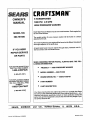
CRRFrSMRN"
OWNER'S
MANUAL
5 HORSEPOWER
1800 PSi
2.5 GPM
HIGH PRESSURE
MODEL NO.
580.751500
WASHER
Each High Pressure Washer has its own model number. Each engine has
its own model number.
The model number for your pressure washer will be found on a decal
attached to the unit.
The model number for your engine will be found on the Blower Housing of
the engine adjacent to the spark plug.
IF YOU NEED
All parts listed herein may be ordered through Sears, Roebuck and Co.
Service Centers and most Retail Stores,
REPAIR SERVICE
OR PARTS
WHEN ORDERING
REPAIR
LOWING INFORMATION:
FOR REPAIR SERVICE CALL
THIS TOLL FREE NUMBER
®
PRODUCT
m
PARTS,
ALWAYS
HIGH PRESSURE
GIVE
THE
FOL-
WASHER
1-800-4,REPAIR
•
MODEL
NUMBER
I
O
ENGINE
MODEL
FOR REPLACEMENT PARTS
INFORMATION AND ORDERING, CALL THIS TOLL FREE
NUMBER:
•
PART NUMBER
1-800-FON-PART
®
PART DESCRIPTION
580.751500
(1-800-473-7247)
NO. _ 133212-0159-01
(1-800_366-7278)
Your Sears merchandise has added value when you consider that Sears
has service units nationwide staffed with Sears trained technicians....professional technicians specifically trained on Sears products, having the
parts, tools and the equipment to ensure that we meet our pledge to you,
we service what we sell.
SEARS,
Part No. 94719
Revision
ROEBUCK
4 (IQt16/95)
and
CO.,
HoffmanEstates,
IL
60179
U.S.A.
Printed
in U,.S.A.
MANUAL DEL
PROPIETARIO
MODELO
NO.
580.751500
!®
UNEA DE AYUDA AL
cu_rEPA_ALA _E
MAO=.ALAVAOOP_A
_
MAQUINA LAVADORA
DE 5 CABALLOS
"=____,_===
D EF U ERZA A, 800 PSI
HORAS:
Lun. - Vie. 8 a.m. a 5 p.m
(TCE)
PRECAUCION:
Lea y Stga tas Reglas de
Seguridad e Instrucciones
Antes
de Operar
Este
Equipo
SEARS,
DE ALTA PRESION
ROEBUCK
.
Ensamble
°
Operaci6n
°
Responsabilidades
o
Servicio
.
Partes de Recambio
and
CO.,
del Cliente
y Ajuste
HoffmanEstates,
IL
60179
U.S.A.
REGLAS DE SEGURIDAD
PRECAUCION:
StEMPRE DESCONECTE
EL CABLE DE LA BUJIA Y COLOQUELO DONDE NO PUEDA HACEN
CON_ACTO
CON LA BUJIA PARA EVITAR UN ENCENDIDO
ACCIOENTAL
CUANDO ESTE INSTALANDO,
TRANSPORTANDO,
AJUSTANDO O HACIENDO REPARACIONES EN SU MAQUINA LAVADORA DE ALTA PRESIOt_L
ENTRENAMIENTO:
e
Los gases de escape dal motor contienen gas de mon6xido de
carb6n MORTAL. Si este gas peligroso se respira en una
concentracf6n suftctente puede causer p_rdfda de ta conctencta
o tncluslve la muerte Opera este equlpo tir'dcamente en dines
ablertas donde hays dlspontble ventilactdn adecuada._
•
La gasol|na el Wtamente tNFLAMABLE y sus vapores son
EXPLOSIVOS No permits que se rums,llamas abtedas, chispes
o ca!or an ta cercania cuando se mardpula gasolina. Evite regar
gasolina sobre un motor caUante., Permits qus la unided se anfY_e
por 2 minutos antes de volverta a cargar con combustible.
Cumpla con toda.s las leyes de mgutac_n de almasenamlento
y manaJo de gasottna,
e
Ubique esta m_!zquinaL_vadora a prmd6n en dines alejades de
matedates combustibles, vapoms combustibles o potvo.
e
Et equips de alia presi6n estd dtsefiado pare set ussdo
dnicamente con las ptezas autortzadas de Sears, El usuado
asume todos los desgos y responsabilidadss si usted uttliza este
equips con piezas qua no cumplan las especifi,caciones mintmas
•
e
Afgunos quimicos o detergantes pueden ser peligmsos si son
inhaiados o ingerldos, causando nausea severs, desmayo o
envenenamiento. Los elementos peligrosos pueden causar
dafio a la pmpiedad o tesk_n severs
•
El rociadode alta presi_n puede causar qua pertliculas de plntura
u otras parttculas sean aemtransportadas y qua vuelen a Wtas
veloddedes
e
Stempre use pmtecck_ ocu_r cuande uttllce este equips o
cuando est_ cerca de donde el equips est_ siendo utJlizadQ.
e
Opera la presi6n an un valor qus no sea mayor qua la presk_n
de Ituido an PSI ctastfk:ada pars su rn_qutna [avadonz a pFss_(_ff11_
•
Nunoa mueva la m_:luina tirando de la manguem dealta pmsk_n.
Ut_tce ta manija co!scads an la parte superior de ta unidad
e
Slempre este segum qua la pistota de mdado, embocaduras y
acoesodos estdn conectados correctamente_
•
Nunca utitice una ptstota de rock,do qua no tenga un segum de
gatUto o un protector de ga611o en posick_n y fundonande
adecuadamante.
e
Use un resplrador ouna rn_scara siempm qua exists el desgo
de que puedan set tnhalados vapores. Lea todas las
instruc_ones de ia rn&scara de manera que est6 seguro qua la
_ra
le propomionard la proteccl6n necesa_ta contra
inhalaci_n de vapores peGgrosos
•
El mciade de alta presk_n puede da_,r elementos fr_gites,
incluyendo vidrio. No apunte la pistols de rociado hacia el vidno
coando est_ an el modo de mciado a chorm
e
Mantenga I_ manguem conectada a ta m_luina o a la pistols de
roctado cuando el sistema estd presurizadeo El desconectar la
manguem m_entras la unidad est_ presurizada as peligmso,
e
Sostenga firmaments la p_tola de mdado en su mano antes de
encender ta ur'_lad. Si no lo hace podrta,ocurdr una lesion debido
W movimiento incontrolado de la pistola de mdadoo No dsje ta
ptstofa de rociado sin atenci_ mientras la m_quina est_ funcic,nande.
•
Et &ms de limpieza dabs tenet incUnaciones y drenajes
adecuades para redudr fa posibilidad de una catda debido a las
supeR_es rasbalosas
•
Mantenga el rociado del agua alejado det alamb_ade ei_ctrico o
puede ocurrir una descarga el_ctrica fatal
•
No ajuste _a vdtvula re<jutadora en una prasi_)n excesiva con
respects a la clash'icaci_n de la m;_luina
•
No asegure el gatif_o de la pistota en la posick_n posterior
(ab_erto)
•
No svite ning0n dispositivo de segundad de la m_.quina.
•
No deje la pLstolaan la posicibn de cerrado pot mds de 5 minutos
con el motor en funcionamiento Esto pod(B dafiar la bombs.
•
Et motor y et silanciador se calientan durante la operaci6n y
perma.necen ca_ientes inmediatamente despu6s del apagado,,
Evita el contacts con el silenciador o almotor catkmte o podria
No permits qua NII_IO-S operen la Mdquina Lavadora a Presi6n
en ningdn momanto.
PREPARACION:
•
Opera el motor r3ntcamente en la velocidad de mando. El hacer
funcionar el motor en velocidades excestvas aumenta el fiesgo
de lesi6n personal
No manipule
las partes qua puedan
aumentar o disminuir la velocidad de mando.
e
No use mpas suettas, joyerta onada qua pueda quedar atrapado
an el arranque oen otras plazas en mtact_.
•
Antes de encender la M_quina Lavadora a Presk_n an clima fdo
revise todas las piezas dal equips y aseg0rese qua no se ha
formado hlelo en elias,
caia o
e
Las unidades con plazas dar'tadas o perdidas, o sin la
cubiertas de protecci6n NUNCA deban set operadas.
e
El silenciador y el depurador de aim deben astar instalados yen
buenas condiclonas antes de operara la M_quina Lavadora a
Presi6n, Estos componantes act0an coma recolectores de
chlspas si el motor produce fuego de retroceso..
e
Revise si el sistema de combustible tJene fugas o stgnos de
deterioro corns ur'_ manguera fr_gil o esponjosa, abrazaderas
sueitas o inexistantes o tanque o taps dafiada Corrija todos los
defectos antes de operar la M_quina Lavadora a Presi(_n,
resultar quemado severamente.
OPERACION:
MANI'ENtMIENTO
•
No rocle Gquides inflamables.
•
Opera y almacene esta untdad sobre una superf'K_e estableo
•
Nunoa dirija la pistols de rociado a personas, an h'nWeso ptantas
e
e
Nunca pennita qua Wguna parts de! cuerpo entre en contacts
con la corriente de! fluido_ NO entre an contacts con un corrtente
de fluids cmada pot una fuga en la manguera de aita pmsi6n.
•
La corriente de alia pmst6n de fluids qua este equips puede
producir puede penatrar la piel y sus tejidos subyacentes,
tlevando a lesi_t saris y posibte amputacibn._
La mar, gu_ra de afta presi_n puede dasermtlar fugas debido al
desgaste, doblamiento, abuso, etc.. El mdado de agaa de una
fuga es capaz de hacer panetrar materials
dentin de la plel.
Siempm inspecclone la manguera antes de useda,, Revise todes
las mangueras pare vet Si existen cortes, lugas, abrask_ss o
abuttamiento de la cobierta, o daiX,
o o movimiento de los acop_es,
Si existe cualquiera de estas condiciones reemptace la
manguera inmediatamente Nunca repara la manguera de aP,a
presidn Reempl_ceta
con otra manguera qua reOna la
clasificacidn de atta presiSn de su m_,quina lavadora a presk_m
I
Y ALMACENAMIENTO:
I
BUSQUE
SIGNIFICA
ESTE
SIMBOLO
"iATENClONll!
PARA
|ESTE
UBICAR
ALERTA!!!
IMPORTANTES
SU SEGURIDAD
PRECAUCIONES
ESTA
DE
EN PELIGRO."
SEGURIDAD.
ESTO
I
I
FELICITACIONES por la compra de su mdquina lavadora
de alta presi6n Sears Craftsman., Esta ha sido disefiada,
proyectada y fabricada para darte la mejor confiabilidady
rendimiento posible.
Si usted expedmenta cualquier problema que no puede
resolver con facitidad, por favor p6ngase en contacto con
su Centro/Departamento de Servicio Sears o Ilame al
n_mero 1- 800 indicado en la cubierta de este manual.
Tenemos tdcnicos competentes y bien entrenados y las
herramientas apropiadas para dade servicio y reparar esta
unidad_
Por favor lea y conserve este manual Las instrucciones
hardn que usted ensamble y mantenga su mdquina
tavadora de alta presi6n apropiadamente Siempre siga las
"REGLAS DE SEGURIDAD".,
ESPECIFICACIONES
DEL PRODUCTO
Especlflcaclones de la M_qulna Lavadora a Presi6n
PRESION DE SALIDA
1800 psi
VELOClDAD
2.5 gpM
DEL FLUJO
MF7CLA DE DETERGENTE
Use detergente sin diluir
TEMPERATURA DEL
SUMINISTRO DE AGUA
No exceder de 140°F
FALTURA DE SUCClON
3 Pies mdximo
Espectflcaclones del Motor
CABALLOS DE FUERZA CLASIFICADO
DESPLAZAMIENTO
MODELO
NUMERO
580.751500
12.6 pu!gadas cL_bica
Champion RCJ8 o su equivalente
0.030 pulgadas (0.76ram)
CAPACIDAD DE GASOLINA
NUMERO
DE SERIE
2 Cuartos U.S.
ACEITE (capacidad de 20 oz.) Peso SAE 30
ESPAClO DE AIRE DE
IGNICCION
FECHA
DE COMPRA
LOS NUMEROS DEL MODELO Y SERIE SERAN ENCONTRADOS EN LA CALCOMANtA PEGADA A LA
MAQUINA LAVADORA DE PRESION_
USTED DEBE REGISTRAR EL NUMERO DE SERIE
Y LA FECHA DE COMPRA Y MANTERLOS EN UN
LUGAR SEGURO PAPA FUTURAS REFERENCtAS.
ACUERDO
BUJIA: Tipo:
Espacio Total
5 HP
DE MANTENIMIENTO
Un Acuerdo de Mantenimiento de Sears est_ disponible en
este producto. P6ngase en contacto con su tienda de Sears
m_s cemana para detalles.
RESPONSABIUDADES
DEL CLIENTE
•
Lea y siga las reglas de seguddado
o
Siga ta programaci6n regular en et mantenimiento,
cuidado y uso de su mdquina tavadora de alta presi6n.
,,
Sigas las instrucciones enlistadas bajo las secciones
de
=Responsabilidades
del
Cliente"
y
"Almacenamiento" de este Manual del Propietario.
0,10125 pulgadas
En el Estado de California es exigido un apagachispas por
la ley (Secci6n 4442 del C6digo de Recursos Pr3blicos de
Califomia). Otros estados pueden tener leyes similares.
Las leyes federales se aplican en tierras federales_
NOTA: Si usted equipa el motor de su m_quina lavadora
a presi6n
con un silenciador
apagachispas,
el
apagachispas debe ser mantenido en funcionamiento
efectivo ordenado por el propietado/operadorUsted
puede
ordenar el apagachispas a trav_s de su Centro de Servicio
Sears, Vea ta secci6n de Partes de Reparaci6n del motor
para los n_3meros de las partes.
TABLA DE CONTENIDOS
REGLAS DE SEGURIDAD
ESPEClFICAClONES
.............................................................
2
RESPONSABILIDADES
DEL PRODUCT ..............................3
SERVICiO Y AJUSTES ................................................
ALMACENAMIENTO
GARANTIA ......................................................................................
3
ACCESORIOS
CONTENIDO
Y CONEXIONES
DEL CLIENTE .................. 14-15
.........................................5
DIAGNOSTICO
DE AVERIAS ......................................
PARTES DE REEMPLAZOINDtCE
DEL PAQUETE DE HERRAJES ................6
16
....................................................................
17
.........................
18
19-28
GARANTIE ..............................................................................29
ENSAMBLE .............................................................................
6-8
OPERACION ................................................................... 9-14
INDICE
-AAccesorios ..................
Aceite del Motor o ............
Almacenamiento ..............
Motor .............................
Bomba de la Mdquina
Lavadoraa Presi6n.............
Antes del Encendido ........
5
12
17
17
16
12
Ensamble de Pistota y Vara, _ o 9
Especificaciones ................
3
Extracci6n...................
13
Carburador ..............
16
Garantia ...................
Mantenimiento
................
Acuerdo ..........................
Motor ......................
Cerrojo de Seguddad
29
2
3
15
Mdquina Lavadora a Presi6n. o,, 14
Bomba ......................
14-16
-D-
Manguera de Alta Presi6n ......
Depurador de Aim
Diagn6stico de Aver'sas .....
18
-EEmbocaduras
..................
10
Chorro ....................
Ensamble
..............
Lista de Revisi6n ..............
11
6-14
8
Rernoci6n de la Caja ............
Herramientas Necesarias ..........
Instalaci6n .................................
7
7
7
Paquete de Herrajes .........
5
Partes para Ordenar ........
6
Partes de Reemplazo. ,., -19-27
-G-
-M-C-
.p.
14
-OOperaci6n ................
2
Aplicaci6n del Detergente ......... 11
Conozca Su M&quinaLavadora a
Presi6n ......................
9
Parado ..................
10
Para Encender el Motor .....
13
Para Encender la M_iquina
Lavadora ..........................
12
Otras Partes ..... p&gina posterior
4
g
Reglas de Seguridad ........
2
Regulador de Presi6n ........
9
Responsabilidades del
Cliente ..................
3,14
Cambio de Aceite ...........
14
Revisi6n del Nivei de Aceite. o_ 14
RecomendacionesGenerales... 14
M&quinaLavadoraa Presi6n ,, _ 14
Reerr_azo de la Buj'ra.........
14
Serviciodel Depuradorde Aire, 15
-SSugerencias de Umpieza ,. _,, 13
-VVelocidad del Motor' . ......
16
ACCESSORIOS
Y CONEXIONES
ACCESORIOS Y CONEXIONESEstos accesodos y conexiones estuvieron disponibles cuando lue comprada la m,iquina lavadora de
alta presi6n.. Tambi_n estAn disponibles en la mayotfa de puntos de venta aI detal y centros de servicio de Sears. La mayor_a de tiendas
Sears pueden ordenar estos elementos para usted cuando proporcione e] nt_mero de modelo de su m_quina lavadora a presi6n. Es
pos_ble que algunos de estos accesorios no se aptiquen a su m&quina lavadora de presi6n.
©
JUEGO DE CONEXION
RAPIDA PAPA LA
MANGUERA DE ALTA
JUEGO
CONEXION
PRESTON
EMBOCADUPA
RAP]DA
DE CONEXION
PAPIDA ACCESORIA
MANGUERA
MANGUERA
ACCESORIA
1800 PSi
-
EMBOCADUPA
PARA CHORRO
2200 y 250 PSi
ENJUAGUE
PAPA
CASNMULTIPLE
F'ROPOS_O
PAP|DA
PAPA LA MANGUERA
A LA
DE ALTA
PRESTON
PARA CHORRO
CONEXION
ACOPLE DE LA
DEL JARDJN CON 2
ADAPTADORES
ENJUAGUE
PAPA
SUPERRCIES
PLANAS
ENJlJAGUE
MEDIDOR
DE
PRESION
PAPA
VEHICULOiBOTE
DESENGRASADOR
,ONTENDIDO
DE LA CAJA DE HERRAJE
Partes empaqetads por separado en la caja
Caja de las Partes
m
Manual del Propietario
Pistola y Vara
Manija
Unidad Principal
a de las Partes
!
(2) Ruades
IAceite para
Manguera de Alia Pmsion
et Motor
Tubo de Recollecctdn
!
de Detergente y Rltro /
Bolsa para las Alambre
Contenldo de la Bolsa de las Partes mostroados
Contenido de la Bolsa de las Partes no
en tama_o completo
mostroados en tama_o completo
(2) Arandelas- M8
(2) Eje defas Ruedas
Soporte de Alambre
(2) Patas de Soporte
Contenido de la Bolsa de las Partes no
mostroados en tama_o completo
2) TorrdllosPr_donemsHexagonaies-M8 x 40ram (2) Ar-,_de_ms
- M 12
(21_
- #10
Conexion Rapida
Tomi]los PdsionerosHexagon_les-M8 x20mm
____
(6)Tuercas de Btida- M8
Embocadura Ajustable
(2) Tomillos Prisionerosde Auto
Entosque-
#10-16
(2) 5/8" Contratuem-.as
(2) Arande|as de Seguhdad-
6
5/8"
(2)Tuerca de Empuje - 1/2"
Tapa de Vinlo
ENSAMBLE
Lea estas instmcciones y el Manual del Operadorporcompleto
antesde intentar ensamblaruoperar su nuevamdquinalavadora
de aJta presi6n, Su rr_quina lavadora de alta presi6n ha sido
ensamblada, en su mayorta,en ta f&bdca,con excepcidn de
aquellaspartesdejadas sin ensamblar. Antesque pueda operar
sunuevamdquinalavadorade alta pmsi6nusteddebe ensamblar
el juego de nJedasy conectarapropiadamentela manguera de
alta presi6no
SI TtENE PROBLEMAS CON EL ENSAMBLEDE SU MAQUINA
LAVADORA A PRESION POR FAVOR LLAMEA LA LINEA DE
AYUDA DE LA MAQUINA LAVADORA A PRESION AL 1- 800222- 313&
HERRAMIENTAS
ENSAMBLE
NECESARIAS
o
Levante ligeramente el extremo del motor de la unidad principal. Esto le permitir_ deslizar cada eje de rueda en los
orificios proporcionados en la parle lateral de ia base (Fig. 1)
CONTRATUERCA
CONTRATUERCA
PARA EL
_t.t÷
VISTA OPUESTA
=
Mazo
=
Llave de cuboscon Cubos de t/2- pulgada o 13 mm
o
LlavesAjustabteo Llaves de Combinaci6n
,= Llave para bJercasde 8mm
PARA RETIRAR LA MAQUlNA
PRESION DE LA CAJA
LAVADORA A
TUERCA DE EMPUJE
FIG. 1
o
Retire ta manija guia (envualta en pldstico),
=
Retire la caja de accesorios de la caja,
=
Retire el ensamble de pistola y vara del soporte de cart6n.
,_
Retire todo el material de empaque de la caja antes de retirar
su m_quina lavadora de alia presi6n
Refi_rase a la P&gina 6, "Contenido det Paquete de Herrajes"
para una lista ilustrada de todos los elementos ir_tuidos con su
m&quina lavadora a presi6n. Familiaricese con carla pieza antes
de ensemblar la m&quina lavadora a presi6n. Compare todo el
contenido con la las Ilustraciones de la P,_gina & Si no encuentra
alguna parte o atguna est_ daRada Itame a la Linea de Ayuda de
la M&quina Lavadora a Presi6n al 1- 800- 222- 3136.
COMO INSTALAR
SU MAQUINA LAVADOR A
PRESION PARA INSTALAR
EL JUEGO DE RUEDAS
o
Apriete cada eje a la base con una contratuerca
=
Coloque una arandela plana M12 sobreel eje y coloquelas
ruedassobrelosejes..
•
Retenga cada rueda a su eje golpeando una tuema de
empujeen el extremodel eje con un mazo.
o
Ensamble los montajes antivibratoriospara soportar las
parascon tomillosprisionemshexagonalesM8-125 x 20turn
y tuercasde bride M8.
_,
Instale las patasde soportea la base como es mostradoen
la Fig° 2 con los tomillos prisioneros hexagonales y las
tuercasde seguridad de brida.Apriete los pasadoreshasta
que las ruedasest6n derechas..
=
Para hacer rn_s f&cil el colocar la manija de agarre en la
manija guia, aplique una sofuci6njabonosa a la manija.
Despu6s que la manija de agarre estd colocada instalela
manijagu'_aa la base corr_ es mostradoen la Fig..2 con dos
tomillosprisionerosM8-1°25 x 40ram, dos amndelasy dos
tuercasde bride M8.
Para instalar el juego de ruedas se necesita de las herramientas
listadas mds adotante, la manija guia y los elernentos incluidos
en la caja de las partes.
de 5/8"- 18.
Instalact6n de la Manlja
Instalaci6n de la
Patas de Soporte
TORNILLO PRISONERO
ARANDELA
ARANDELA
SOPORTE DE CABLE
TORNILLO
TORNILLO
FIG. 2
PR|SONERO/_
ENSAMBLE
o
Una elsoportede atambm a la manijaguiaconlos tomigode
auto enmsque #10 y las a.randelasplanas M6 (Fig+3). E1
enrmlladorde la manguera debe estar a ta izquierday el
sostenedorde ta pistola a la derech& Aseg_3reseque la
curvaturadetsoporte estd apuntando hacia arriba Co|OqL_e
la tape de vinilo en et sostenedorde la pistot&
SOPORTE
•
Una el acople con cinia de tefl6n al ensambte de pistola y
vara (Fig, 5), Usted puede girar la pistola o la rnanguera pare
asegurar la conexidn+ Aprietela con una Ilave ajustable,
DE ALAMBRE
] j
CINTA DE
PASADORES
MANMA
GU]A
SOPORTE
DE ALAMBRE
FIG. 3
PARA ENSAMBLAR
REMANENTES
LOS
FIG. 5
=,
COMPONENTES
Conecte el otroextreme de la manguera de alta presi6nal
acople met&licesuperiorde la bomb& Aprietetocon la Uave
ajustable(Fig. 6).
IMPORTANTE: USTED DEBE ENSAMBLAR LA VARA Y
CONECTAR TODAS LAS MANGUEF_.S ANTES DE ENCEN°
DER EL MOTOR. LA BOMBA SE DANARA SI EL MOTOR ES
ENCENDtDO SIN TENER TODAS LAS MANGUERAS CONEC+
TADAS Y EL AGUA SUMtNISTRADA
,,
Inctuidacon estd unidadhay un acopte de conexi6nrdpida
que usted conecta a la entrada de agu&. Este puede
separame en dospartes - un coneclormacho y un conector
hembra que contiene un tamiz de entrada. Asegdrese que
esta tamiz est_ limpioas1cometarnbi6nel filtro en el acopte
de enttada del agu& Conecte el acoplede conexi6nrdp=de
al acople pl&sticoinferioren la partefrontal de la bomba(Fig.
4). El conector macho negro estd en el lade que usted
conectael acoplepldstico+
MANGUERA
DE
ALTA PRESTON
ENTRADA
AGUA
FtLTRO
ENTRADA
FIG. 6
CONECTOR
HEMBRA
LISTA DE REVSION
.,/,
TAMtZ DE
MACHO
ENTRADA
/
•
Revise los pasadores _jue utiiiz(_para instalarel juego de
ruedas y que las rnanijas est_n apretadas+ La vibraci6n
durante elfuncionamientopuede soltar los pasadoresque
no estdn suficientementeapretados+
•
Revise que lasconexionesde ta manguera estdn bien (alia
pres_d_y suministro de agua) y que las conexiones est6n
apretadas y que no existan dobleces, codes, o daSo a la
manguerade attapresi6n,,
e
Aseg_reseque el nivelde aceiteen el motorest_ en el nivel
correcto+
=
Pmporcioneel suministrode agua apmpiado(que noexceda
tos 140 F)+
e
Aseg0rese_de.
leer las seccionesde =Reglas de Seguddad"
y operaci6n antesde utilizarla m&quina lavadora a pmsi6n+
FIG. 4
Desenmde ta manguera de atta presiSny revise que las
roscas en un extreme est_n cubiertasapmpiadamentecon
cinta de tefl6n. Si no hay cinta aplicada apmpiadamente,
coloquede nuevo de rr_nera que tas roscasest_ncompletamentecubierta&La cintasella la conexibnde ta manguera
at ensemblepistolay varao
OPERACDON
CONOZCA
SU MAQUINA [LAVADORA A PRESION
LEA ESTE MANUAL DEL PROPIETARIO Y LAS REGLAS DE SEGURIDAD ANTES DE OPERAR SU I_&,QUINA LAVADORA DE
ALTA PRESION, Compare las ilustraclones con su mdquina lavadora de alta presi6n para familianzame con las ubfcaciones de los
diferentes controles y ajustes.. Conserve este manual para referencias futuras.
TUBO DE RECOLECCION
DE DETERGEN'TE
Y FILTRO
BUJIA
ANILLO PROTECTOR
DE LA EMBOCADURA
MANGUERA
DE ALMACENAMIENTO
DE REPUESTO
DE ALTA PRESION
MANUA
LLENADO DE ACEITE
CONTROL
DE ENCENDIDOIAPAGAOO
DEL MOTOR
PRESIL,LA PARA
ALMACENAMIENTO
REGULADOR
ENSAMBLE DE PtSTOLA
Y VARA
DE PRESlON
DE AIRE
DE LA VARA
ENTRADA
DE AGUA
F|LTRO
!NTRADA
SOPORTE DEL
CONECTOR
HEMBRA
SALIDA
PRESION
TAPA DE LA GAS(
TAM1Z DE tENTRADA
ARRANQUEDERETROCESO
CONEXtON RAPIDA
FIG. 7
MANGUERA DE ALTA PRESTON -- Conecta un extremo a la
bomba dol agua y el otro a la vara de rociado.
FILTRO DE SUMINISTRO DE ENTRADA -- Filtra el suministro
de agua de entrada.
.
TUBO DE RECOLECClON
DE DETERGENTE Y F1LTRO
Mezcla el agua y el detergente en el flujo de agua de salida_
BOMBA -- Desarrolla la alta presi6n,
REGULADOR DE PRESION -- Le permiteajustarta pmsibnde
ta corrientede salida.,
CONTROL DE ENCENDIDO -- APAGADO DEL MOTOR Coloca at motoren e! modo de encendidopara el arranquede
retr(x:eso;APAGA el motor en funcionamiento.
ARRANQUE DE RETROCESO _ Usadopara encender et motor
manualrnente,,
SALIDA DE ALTA PRESION -- Conexi6n para la manguera de
alia presidn_
DEPURADOR DE AIRE -- Elemento de filtro tipo seco que limita
la cantidad de suciedad y polvo que llega al motor°
CONEXtON RAPIDA--Conexi6n
de entmda
ENSAMBLE DE PISTOLA Y VARA -- Contmla la aplicad6n de
agua sobre la superficie a timpiar con el disposifivo de gatitlo_
lncluye e! cerrojo de seguridad_
9
fdcil para el suministro de agua
OPERACION
COMO
UTILIZAR
SU MAQUINA
LAVADORA
SI TtENE ALGUN PROBLEMA AL OPERAR SU MAQUtNA
LAVADORA A PRESION POR FAVOR LLAME A LA LINEA DE
AYUDA DE L.AMAQUINA LAVADORA A PRESION AL 1* 800222- 3!36.
_?_RADO DE SU MAQUINA LAVADORA A PRESION
=
Prirnero,mueva el mando del rnotot o del equipo hasta |a
.... posici6nde OFF(FIg. 8).
EMBOCADURA
FAST
AJUSTABLE
EMBOCADURA
FIG. 9
DE CHORRO
FIG. 10
Con la emboc_dura ajustable usted puede ajustar el patr6n de
rociade para que sea de alta o baja prest6n_ Tand_n puede
ajustar el roc_do de manera que est_ concentrado en un pa_6n
de corrlente o expandido en un patron de abanico,. Utilice esta
ernbocadura para aplicar detergente
OFF I.DLE
=
Empuje la conexi6n de fa embocadura hacia adelante
cuando desee ajustar el rociado al modo de baja presi6n (Fig.
11). Tire la embocadura hacia atr&s para obtener la alta
presi6n.
=
El girar la embocadura hace que se ajuste el patr6n de
rociadode una cordenteangostaa una corrienteexpandida+
=
Tambi_npuedeajustarla presi6ngirandola pedlladel control
de presi6n(Fig..t2) al valorde presi6ndeseade.El giraresta
peritla pot completo en sentido de las manecillasdel reloj
producelas pmsi6nm&salta. No desatomille la v_lvulade
controlde presi6ndemasiadoporquese saldr_porcomplatoo
FIG. 8
,=
Con el simpleAPAGADO del motorla pmsi6ndel sistemano
serd libeiada. Tire del gatillodel ensamble de la vara de
rociadopara tiberar la presi6nde la mangueraoNOTA: Una
pequeff_acantidad de agua saldr_ cuando usted Iibere la
presi6n.
EMBOCADURAS DE ROClADO
Su m_quina lavadora de alta presi6n viene equipadacon una
selecci6n de dos conexionespapala embocadurade rociadouna embocaduraajustable(Fig. 9) y una embocadurade chorro
(Fig° !0)+ Conecte cuatquiera de las embocadura como es
mostrado en la Fig° 9 y APRIETE CON LA MANO la perilla
pldstica
._OMO UTILiZAR LA EMBOCADURA
DISMINUtR
AJUSTABL_DVERTENC_:
NUNCA AJUSTE EL
PATRON
DE ROCIADO
CUANDO
ESTE R_
CIANDO.
NUNCA COLOQUE
LAS MANOS EN
FRENTE DE _
EMBOCADURA
DE ROCIADO
PARA AJUSTAR EL PATRON DE ROCIADO.
FIG. 12
<k_Y'
EMBOCADURA EN MODO
DE ALTA PRESION
EMPUJE LA EMBOCADURA
HACIA
GIRE LA EMBOCADURA PAPA
EXPANDIR LA CORRIENTE
DEL ROCIADO
ADt=LANTE PARA EL MODO DE BAjA
PRESTON Y LA APLICACION
DEL
DETERGENTE
FIG. I1
I0
GIRE LA EMBOCADUP, A PAPA
HACER ANGOSTA LA
CORRIENTE DEL ROCIADO
OPERACION
APUCAClON
DE DETERGENTE
CADURA _-JUSTABLE
CON LA EMBO-
LAVADO/ENJUAGUE
IMPORTANTE: UTILICE DETERGEI_q'ES DISEI_ADOS ESPECIFtCAMENTE PARA MAQUINAS LAVADORAS A PRESION,
LOS DETERGENTES
CASEROS
PODRIAN
DANAR LA
BOMBA,
Conecte el suministro de agua (Fig., 15).,
o
Aju_e la embocadura pare seleccionar
peNt6n (vea la Fig. 11).
el mode de alia
ADVERTENCIA:
EXTREMADAMENTE
CUF
DADOSO SI TIENESEA
QUE
UTIMZAR LA MAQUINA
LAVADORA A PRESION DESDE UNA ESCALERA,
ANDAMIAJE O CUALQUIER OTRA UBICAClON
RELATIVAMENTE
INESTABLE. LA PRESION DE
UNA MAQUINA LAVADORA FUNClONANDO
SE
ACUMULA EN LA VARA A MEDIDA QUE USTED
SUBE. CUANDO OPRIMA EL GATILLO LA FUERZA
DE REACCiON DEL ROCIADO tNICIAL PUEDE
HACERLO CAER, O SI USTED ES'fA MUY CERCA
DE LA SUPERFtCIE QUE ESTA LIMPIANDO LA
ALTA PRESION LO PODRtA HACER CAER DEL
DISPOSmVO ELEVADO SOBRE EL CUAL ESTA.
IMPORTANTE:
USTED
DEBE
CONECTAR
TODAS
LAS
MANGUERAS
ANTES DE ENCENDER
EL MOTOR,, EL ENCENDER EL MOTOR
SIN TENER
TODAS
LAS MANGUERAS
CONECTADAS
HARA QUE LA BOMBA SE DAI_Eo
Lasrr_quinas tavadorasa presi6n son herramientasde limpieza
fitiles disei_adaspare limplar casi cualqutersuperficieen dos
pasos sencilios,,
o
A PRESION
o
El primer paso involucre la aplicaci_n de uPasolucibn detergente/disolventeapropladapare penelmry soltar la rnugre.
E1 deter_lentees apticado a _
presk_.n,pa:ra evitar.el
saq:wcarruemo,roc=aooexcesrvoy aesper_c_oouejeja sotuci6n sobre la superflciede 3 a 5 mfnutospare permitirque la
soluci6nacb3e,
=
Et segundopaso tnvolucrala superficiea limpiarque usted
a preparado conla _uina
lavadora a presi6ny despu6sel
enjuagarlahastadejada limpiao
Pareaplicar el detergenteriga estospesos:
=
o
ENTRADA
Prepare susoluci6n de detergente come sea requeridoper sutrabajo.
DE AGUA
SUMINISTRO
DE AGUA
Coloque el filtro pequer3o
del tube transparente de
recolecci6nde detergante
"dentro det recipiente del
detergente (Fig° 13),
=
Coloque la embocaduraen
el mode de baja pmri6n,,El
detergente no puede ser
extraido con la emboFIG.)3
caduraen et mode de alta
presi0n (vea la Fig, 11)4
,.
f
o Encienda
la mdquina
AUMENTAR
lavadora y aplique el detergenie a una superficie
seca, comenzando en la
parte de abajo y terminando en taparte dearriba,,
Tambien puede concentracionde detergente girando
ta peritto del detergente
(Fig.,14)
o Retire el sif0nde la botella
pare deteneret detergente
FIG. ]4
en el modede baja presi6n,
NOTA: Los detergentes son rn_s electivesapticadossobre superlicies secas.
COMO UTILIZAR
CHORRO
LA EMBOCADURA
FIG. 15
NOTA: El detergente no fluird cuando est6 en el mode de alia
presk_no Encienda la mdquina lavadora y didjase de ta parle
superior de la supedicie a la parte de abajo,
=
Encienda la mdquina lavadora y dir'_ase de la parte superior
de la superficie a la parte de abajo,
NOTA: El mode de alia presi6n es mds elective cuando la punta
de la vara estd sostenida entre 6 pulgadas a dos pies de la
supefficie que estd siendo limpiada,,
ALMACENAMIENTO
DE LAS EMBOCADURAS
Estd incluido un soporte pera las embocaduras en la baser Usted
puede mantener la embocadura que NO est6 utilizando en ese
soporte (Fig., 16),,
PARA
•
La embocadura para chorro giratoria, en esencia, expande
el drea de la cordente de alta preri6n.
o
Usted no puede ajustar el patr6n de rociado con esta embo-
cadura.
EMBOCADUPA
o
Usted no puede aplicar detergente con esta emb(x_dura,
(opcgal)
FIG. 16
11
DE
OPERACION
ANTES
DE ENCENDER
GASOLINA
EL MOTOR
ADVERTENCIA:
NUNCA
LLENE EL CERRADOS.
TANQUE DE
COMBUSTIBLE
EN RECINTOS
NUNCA LLENE EL TANQUE DE COMBUSTIBLE
CUANDO EL MOTOR ESTA EN FUNClONAMIENTO
O CALIENTE. NO FUME CUANDO LLENE EL TANQUE DE COMBUS13B_.
Para operar el motor usted necesitardIo siguiente:
ACEITE PARA EL MOTOR:
tMPORTANTE: CUALQUIER INTENTO DE HACER GIRAR O
ENCENDER EL MOTOR ANTES QUE ESTE HAYA REClBIDO
SERVICIO APROPIADO CON EL ACEITE RECOMENDADO
RESULTA EN UNA FALLA DEL MOTOR.
ADVERTENCIA: NUNCA _NE
EL TANQUE DEL
COMBUSTIBLE POR COMPLETO. LLENE EL TANQUE A APROXIMADAMENTE
t/2' POFI DEBAJO DE
LA PARTE INFERIOR DEL CUELLO DE _NADO
PAPA PROPORCIONAR ESPACIO PARA LA EXPANSION DEL COMBUSTIBLE. UMPIE CUALQUIER DERRAMAMIENTO DE COMBUSTIB! _ DEL MOTOR O
EQUIPO ANTES DE ENCENDER.
Esta incluida una botella de aceite de 27 oz,. SAE 30 en la caja
de las partes,
NOTA: Cuando agregue acelte a ia caja del olgOetrml det motor
use t3nicamente acette delergente de atta caltdad con la clasific_
ci6n de servicio API SF, SG o SH, con peso SAE 30. Selecolor=
et grado de viscosidad del aceite de acuerdo a su temperatura de
funcionamiento esperadao
I
mds frio
!
,,
32°F
a
m&s caliente
sAE o
i
!
Aunque los aceites de m01tiple viscosidad (5W30, 10W30, etc.)
mejoran el encendido en ctirna fdo eltos crean aurnento en el
consumo de aceite cuando son usado pot debajo de 32 °F+ Revise
et nivel de acette de su motor rods frecuenternente para evitar
da£_o posible de hacer funcionar el motor con poco aceite+ La
capacidad del sumidem del de aceite es de 20 onzas_
o
Coloque la mdquina tavadora a presi6n de manera que el
motor est_ nivelado,
o
Limpieel drea alrededordel odficiopara el aceile y retireta
varillade medici6n de aceiteo(Fig. 17)..
o
Use combustible timpio y alrr__.dnelo en recipienles cubier+
tos, limpio y apmbados+ Use err,budos de tlenado timpios.
Nunca utilice gasotina "vieja" dejada de la Liltima estaci6n o
gasolina almacenada por largos pedodos de tiempo,,
IMPORTANTE: ES IMPORTANTE EvrrAR QUE SE FORMEN
DEPOSITOS DE GOMA EN LAS PARTES IMPORTANTES DEL
SISTEMA DEL COMBUSTIBLE COMO EL CARBURADOR, EL
FILTRO DEL COMBUSTIBLE, LA MANGUERA DEL COMBUS. TIBLE O EL TANQUE DURANTE EL ALMACENAMIENTO, TAMBIEN LA EXPERIENCtA INDICA QUE LOS COMBUSTIBLES
MEZCLADOS CON ALCOHOL (LLAMADOS GASOHOL O QUE
UTILIZAN ETANOL O METANOL)
PUEDEN ATRAER LA
HUMEDAD LA CUAL CONLLEVA A SEPARACION Y FORMACION DE ACIDOS D_UP,
ANTE EL ALMACENAMIENTO. EL GAS
ACiDO PUEDE DANAR EL SISTEMA DEL COMBUSTIBLE DE
UN MOTOR EN ALMACENAMIENTO. PAPA EVITAR PROBLEMAS DEL MOTOR EL SISTEMA DEL COMBUSTIBLE DEBE
SER DESOCUPADO ANTES DE ALMACENARLO POR 30 DIAS
O MAS VEA "ALMACENAMIENTO"
EN LA PAGINA 17+NUNCA
USE PRODUCTOS LIMPIADORES
PAPA MOTOR O CARBURADOR EN EL TANQUE DEL COMBUSTIBLE, DE OTRA
FORMA PUEDE OCURRIR UN DANO PERMANENTE
a
Limpie el drea alrededor de la tapa de Uenado de combustible, retire ta tapa,
=
Agregue gasolina regular "SIN PLOMO", lentamente hasta
IIenar el tanque
•
Instale la tapa del combustible y limpie cuatquier detrains de
gasolina.
PARA ENCENDER
LA MAQUINA
LAVADORA
FIG. 17
Limpie la varilta de medici6n, insdrtela en el orificio para
llenade de aceite y apdetela firmemonte. Retire la vadlla de
medici6n de aceite. Si et aceite no estd basra la MARCA
LLENO de la varilla de medici6n agregue et aceite recornendado, VIERTALO LENTAMENTEo
o
El fabdcante recomier_ia gasotina para autom6vil regular sin
contenido de plomo, I+mpiay fresca con un mlnimo de 77 octanos
(La de grado regular con plomo es un substttuto aceptabte), La
capacidad del tanque es de 2 U. S,, cuartos.
=
Conecte un extremo de la manguera del jard'_ a una fuente
de aaua frta. El suministro de agua no debe exceder los
140°t[= (55 °C),,
Revise que la manguera de alta presidn estd conectada a la
salida de ta bomba y que el suministro de agua est_ conec.
tado a la entrada de la bomba.
Limpie la vadlla de medici6n cada vez que sea revisado el
nivel de aceite,.
tMPORTANTE: NO LO LLENE POR ENCIMA DE LA MARCA DE
"LLENO" DE LA VARILLA DE MEDlClON+
o
ABRA el agua.
a
o
Optima el gatillo del ensemble de pistola y vara para hacer
que el aire salga de la manguera de alta presi6n.
=
Ajuste la embocadura a la presi6n correcta y el dngulo de
rociadooTambi_n puede girar fa perilla de control de presi6n
al valor de pres_6n deseado,.
=
Vierta aceite de la botella que viene incluida denim de la
apertura de Iienado del aceite,
Instale la variUade medici6nde aceite, aprietetacon la mano
firmemente
]2
OPERACHON
=
=
Opdma el gatillo de ta plstota de la rr_quina lavadora a
presidn(Fig. 18),,
Encienda el motor de acuerdo a "PARA ENCENDER EL
MOTOR.,"
o
Co!oque la, palanca de control del motor en posici6n de
RAPIDO (FAST),
=
Agarre la manija de retroceso de encendido del motor y tireia
hacia atrds lentamente hasta que esta se ponga tensa, Deje
que ta soga se enrosque lentamente,, Despuds tire de la soga
con un movimiento de brazo completo y rdpide,, Deje que la
soga regrese lentamente (Fig, 21).,
GATiLLO
FIG. 18
PARA ENCENDER
EL MOTOR
IMPORTANTE:NO HAGA FUNCIONAR LA BOMBASIN TENER
EL SUMINISTRO DE AGUA CONECTADO. NO PERMITAQUE
LA BOMBA FUNCIONE M_S DE 5 MINUTOS SIN PREStONAR
EL GATiLLODE LA PISTOLA. ALIVtELA PRESION Y APAGUE
LAUNtDADSIESTA FUERA DE USO POR MAS DE5 MINUTOS
SIN TtRAR DEL GATILLO. USTED DEBE SEGUIR ESTA PRECAUCION O LA BOMBA SE DAI_ARA+
=,
Oprima el gatillode la vara de la m_quinalavadora a presi6n
para liberar la alta presidn y/o purgar la manguera oe entrada
de aim
=
Ajuste el cerrojo de seguridad en la posici6n de
ENCENDIDO. Esto inactiva al gaUItode manera que usted
no pueda realizar un rociado accidental de alta pres_6n(Fig.
FIG. 21
o
Si el motorno se enciende despuds de tres intentos, cebe el
motor de nuevopor5 veces,optima el ga811o
para liberarla
prest6ny tire la soga del arrar,que de nuevo.
=
Una vez que se haya encendido coloque el Cerrojo de
Seguddaden la posicidnOFF°
o
Optimael gatillodel ensamblede la pistolay vara,,Debe salir
agua porla embocadura,
Su rndquinalavadoraa presi6nest_ listapara ser usada,
e
EXTRACClON
Nosotrosno recornendamosque sutomesu surninistrode agua de
fuentBsdiferentesa ia conexi6nde surnir_tro de agua de [a casa
19).
SUGERENCIAS
o
Inicialmente limpie un &rea y revise si la supe_cie tiene
dafios,,Si no encuentradafiospuede asumirque est&bieny
puede continuarlimpiando_ Los detergentes act_an mejor
cuandose aplicansobreuna superficieseca
=
Para una lirnpiezamds efectiva, mantengala embocadura
de rociadeentre 8 y 24 pulgadasde la superficieque estd
limptandoo
Permitaque el detergente act_e entre 3- 5 minutosantes de
lavary enjuagar,
w
FIG. 19
=,
Cotoque el rnar,:lodel estrangulatoro la palar_, decontrol
del equipo en posict6nde "ESTRANGULADOR o CHOKE°
(Fig°20),
FIG. 20
13
=
Para limpieza, comienceen la porci6ninferiordel drea a ser
lavaday didjase hacia arriba, utilizandomovimientos largos
y superpuestos.
Pard enjuague, empuje la manga de la embocadura a alta
presl6ny espere que el detergentesea eliminado+,
Comience
en laparte superiordel &reaque va a serenjuagadadirigi_ndose hacia abajo con la misma clase de movimientosutitizadospara la limpieza
o
Nunca utilicela entrada del agua para extract detergenteo
cera+
o
Ustedpuededafiarla superficieque estd limpiando siacerca
demasiadoia err_.adura de rociado, especialmenteutilizando el modo de alta presi6n.
,,
La lfmpiezano serd muy efectivasi tiene la embocadura de
rociado muy lejos.
•
No se acerque rnds de 6 pulgadas cuando est6 [impiande
llantas de autorrK_vites,
ESPONSABIL|DADES
DEL CLIENTE
INTERVALO DE OPERACION POR HORA
TRABAJO DE MANTENIMIENTO
COLOQUE LAS FECHAS A MEDIDA QUE
COMPLETE SU SERVICtO REGULAR
TRABAJO
Cada 25
Ante=
Horu o
Cada Anualmer
U_o
te
DE MANTENIMIENTO
.....
MAOUlNA LAVADORA A PRESION
1. Revisar filtro de enttada y tamiz.
xt
2. Revisar rnanguera de alta prest6n.
X
3, Revisar la manguera det detergente.
X
Cada 10.3
Ho¢_ o
Cads ,50 Anualment
Ho_d
•
FECHAS DE SERVIClO
m
....".......
T
/
I]
4. Revisar pot fugas en pistola y vara.
5. Cambiar bomba de aceite.
MOTOR
1. Revise el nivelde aceite,
12.Cambie el aceite del motor.
3, De servicio al depurador de,a!m,
=m
4. Reemplace la bujia.
5, Prep_relo para almacenaje,?*
Prepare la unidadpara almacenamientosiva a
permanecerfuera de funcionamiento por mdsde
30 d'_s
t" Limpiar si estd obstruido, Reemplazar sl estd perfo_ado o rasgade,
_: Cambiar aceite despu6s de las primeras 2 horas, despuds carla 25 horas.
* Cambiar rn&s _pido cuando funcione bajo carga pesada o alta temperatura ambiente_
** Umpiaz rr_s a menudo bajo condiciones polvorientas o cuando hay parttculas aemtzansportadas
RECOMENDAClONES
de entrada de la bomba, Limpie los filtros si est_n obstruidos
o
reemplace la conexi6n rdpida si el tamiz del fittm o el fittro del
acoplede entrada est_n desgarrados_
GENERALES
La garantia de la rn,_luina lavadora a presi6n no cubre los
elementos que hayan sido sujetos a abuso o negligencia del
operador, Para recibir un cubdmiento completo de la garanf=a el
operador debe seguir las pautas descrilas en este manuaI,Ai.
gunos ajustes serdn necesarios peric_licamente para mantener
apropiadamente su rr_quina tavadora de alta presiSn,
Revise la Manguem de Alta Presldn: La manguera de aria
presi6npuededesarrotlarf!ugasdebidoa desgaste,doblamiento,
abuso, etc..El rociadode agua de una fuga es capaz de inyectar
material dentro de la piel. Inspeccionela manguera cada vez
antes de usada Revise todas las mangueraspara ver si tienen
cortes,fugas, abrasioneso abuttamientosde la cubierta,o da_o
o movimientode los acoples Reerr_ace la manguera inmediatamente si cuatquierade estas condicionesexisteoNunca
repare la manguera de aria presi6n., Reemptdcela con otra
manguera que m0na la clasificacidnde presi6n minima de la
n_quina tavadoraa presi6n
Todos los ajustes de la secci6n de Servicio y Ajustes de este
manual deben ser hechos al rnenos ur,a vez pot temporada
=
Una vez al ai_ debe reemplazar la buj'B y timpiar o reerm
plazar el filtro de aim y revisar si el ensamble de pistola y
vara est_ desgastadoo Una bujia nueva y un filtro de aim
ti_io as.eguran una mezda de aim- combustible apropiada
y e ayuoa a su rno[or a tuncionar mejor y a durar rn_s_
ANTES
DE CADA
USO
Revise el nivel de acette det motor_
Revise si el fittrode enbada del agua y el tamiz de la conexi6n
rdpidaestdndaflados,,
Revise st hayfugas en la rnanguerade alta presi6n_Revisesi la
manguemde entradade detergentey et filtm estdndafiados.
Revise si hayfugas en el ensamblede ptstolay vara,
MANTENIMIENTO
PRESlON
presentes
DE LA MAQUINA LAVADORA A
Revise et FIItro de Entrada ye! Tamiz: Retire la conexi6n rdpida
y examine el tamiz de entrada del conector hembra yen el acople
]4
Revise ia Manguera del Detergente: Examine el filtm de la
manguera del detergente y limpielo si est& obstruido_La
manguemdebe adaptarse con seguridaden el acople conpuas.
Examinesi la rr_nguera tienefugas o rasgaduras_Reemplaceel
filtroo la manguerasi algunode los dos est6 dafiadoo
Revise la Plstola y la Vara: Examinelaconexi6nde ta manguera
y aseg_rese que estd apretada, Pruebeel gatillopresiondndolo
y asegur_ndose que est6 se devuelve a su tugar..Coloqueel
cerrojode seguridaden la posici6nON y pruebeet gatillo,.Usted
no debe ser capaz de oprimirel gatillo.
RESPONSABlUDADES
MANTENIMIENTO
DEL MOTOR
Revtsk_mdel Nlvel de Acelte:
Vea"ANTES DE ENCENDER EL MOTOR"para obtenerinformao
ci6n en la revisi6ndel nivelde aceite. El nivelde aceitedebe ser
revisadoantes de cada uso o al menos cada 5 horasde opeP
acibn. Mantenga et niveldo aceite,
Camblo de Acella:
=
=
[A
DEL CLUENTE
ELEMENTO DEL"'
_pEPURADOR
DE AIRE
Cambie el aceito despu6sde las primeras2 horasde operaci6n. Cambie el aceite cade 25 horasdesde ese momento
en adelante,Cambteel aceite mdsa menudesiestd usando
su rn_quinalavadora a presJ6nbajocondicionesdesuciedad
o potvoextremas,o en clima extmmadamente caliente,
Cambie etaceitemientrasel motorse encuentreauncatiente
porfunctonamientode la siguientemanera:
FIG. 23
PRECAUCION:
DESCONECTE
EL CABLIE
DE LA I
BUJIA
Y MANTENGALO
ALEJADO
DE LA MISMA.
Llmpie el drea alrededor del tap6n del drenaje de aceite, retire et
tap6n y drene e! aceite por completo en un recipiente indicado
(Fig,,
22).
ft.., t _/
//
TAPON DEL DRENAJE DE ACEITE
/
o
Afloe los tomfltos y quite a contlnuaci6n la tapa_ LImpie
minuciosamente dnetro de ta base y la cubierta
o
Para dar servicio al cartucho, limpielo golpe_ndolo suavemente sobre una superficie ptana. Si se encontrara muy sicio,
cdmbielo por uno nuevo, No Io engrase,.
o
Vuelva a instalar el cartucho,, Coloque de nuevo la tapa y
apriete los tomillos o la perilla firmemente,
Llmple et Ststema de Enfrlamento
del Motor:
Retire los testes de hierba y sucidea de la rejitla rotante o de ta
placa protectora cada 8 horas o diadamente (o mds a menudo si
fuera necesado) para impedir que el motor se dahe como consecuencia de un recaltentamiento (Fig. 24).
'FIETIRE LOS RESTOS
DE BRAZOS Y SUClEDAD
FIG. 22
=
Cuando todo et aceite haya drenado,
tap6n de aceite°
=
Retire ia varilla de medici6n de aceite. Limpie la variila de
medici6no
=
Liene ta caja del cig0eSal del motor con aceite hasta que el
nivel del aceite est6 on el punto de =LLENO" de la varilla de
medici6n de aceite. No Ilene en exceso por encima de la
mama, Se necesitan aproximadamente
20 onzas., VIERTALO LENTAMENTE.
e
instale y apriete el
FIG. 24
Reemplace la Bujia:
Irt.stale y apriete la varilta de medici6n de aceite cuando la
caja del dgt3eP._ldel motor es Ilenada al nivel apropiado
Cambie la bujiacada 100 horas de operaci6no una vez al afio,
Io que so presenteprirnero,Esto le ayudard at motor a encenderse mds fdcilmentey a funcior_r mejor,.Vea lasespecificaciones de la rndquinalavadora a presi6n para saber el tipode bujia
que necesita, El espacio de la bujia es de 0,030 pulgadas
(O,76mm)°
De Servlclo el Depurador do AIre:
Su motor no funcionard apmpiadamente y se puede dafiar si Io
hace funcionar utilizando un depurador de aim sucioo
Limple o reemptace el filtro de papel del depurador de aire una
vez cada 100 horas de operacibn o una vez al afio, to que se
pmseote pdmero. Umpie o reemplace n_s a menudo si su motor
funciona en condiciones potvorientas o do mucha suciedacL Los
repuestos estdn disponibles en su Centre local de Servicio Autod-
zado Sears,
Para !impiar o reemplazar et depurador de aim (Fig., 23):
•
Suelte los tomigos de la cubierta (estos no necesitan
mtirados) y
ser
15
RESPONSABILIDADES
DEL CLIENTE
=,
Inserte un embudo y agregue aceite recomendado
SAE 80W-90, despu_s instale el Tap6n de Llenado de
Aceite.. La capacidad es 9 onzas (275ml)o
=
Instale de nuevo et tap6n de Ilenado e aceite de la bomba y
instale de nuevo el escudo de la bomba_
Purgar Alre de la Bombay Suclo:
Para quite aire de la bomba, siga estos pasos:
TAPON DEL DRENAJE
DE ACEITE DEL BOMBA
S
•
Coloque el maquina lavadora de presiSn vea Ensamble
instrucciones y conecte el sumtnistro de agua.
=
Quite el embocadura del pistola.
•
Opdma el gatillo de la pistola y agarre_
Para retire sucio de la bomba, siga estos pasos:
FIGo 25
o
Cotoque el maquina lavadora de presi6n yea Ensam,ble
instrucciones, conecte el suministro de agua, y encenaer eu
motor vea instrucciones en OPERACION
•
=
Es ajustepermitamotorel arranque y calienteantes
Cuando todo el aceite haya drenado, ir_staley apriete el
tap6nde aceite_
=
Quite el extensi6n de embocadudra de la pistota.
e
Retiree! tap6n del Llenadode Aceitedel al partesuperiorde
ta bomba_
•
Optima el gatiflo de la pistola y agarre
e
Cuando el suministro de agua es constante, conecte extensi6n de embocadura y encender la bomba
SERVIClOS Y AJUSTES
VELOCIDAD
TORNILLO
DEL MOTOR
DE AJUSTE
_LOCIDAD
,_
DE"
ACELARADOR
DE RALENTI ' d
ADVERTENCIA:
MANIPULE EN
EL LA
MANDO
DEL MOTOR EL NUNCA
CUAL AJUSTADO
FABRICA A LA VELOClDAD DE MOTOR APROPIADA.
EL COLOCAR EL MOTOR EN UNA VELOCIDAD
EXCESIVA POR ENCIMA DEL VALOR DE ALTA
VELOClDAD DE LA FABRICA PUEDE SER PELIGROSO.
IMPORTANTE: EL CAMBtAR LA VELOCtDAD DE MANDO DEL
MOTOR CANCELARA LA GARANTIA DEL MOTOR_
AJUSTE
ACELERADOR
VALVULA
DE AGUJA
FIG. 26
DE MOTOR
Pueden requerirsepequefiosajustes del carburadorpara corrv
pensar las diferencias en combustible,temperatura, altitud o
carga.Etflltrode aim y latapa del mismo deben ser montadosen
el carburadorantesde arrancar el motor
o
Apagueel motor y apague el suministrode agua.
o
Retiredispositivode degocon pistota.
=
Retire embocaduradetextr6rnode dispositivode riegocon
2rnmor 5/64 llave (incluido en la juego)o
AJUSTES INICIAL
e
Con alambm inctuidoen juego o ctavijopara Umpiematerial
extrafio del embocadura ('Fi(:l.27_ .......................
,,
Gire suavemente la v&lvula de aguaja en el sentido de las
aguajas del reloij hasta que APENAS cierre. Si gira demasiado la v,tlvula se puede da5ar.
,=
Abra despuds la vAIvuta de aguaja 1 vuelta y 1/2 en sentido
contrario alas a contrario alas agujas del reloi (Fig. 26).
AJUSTE
FINAL
•
Arranque el motory permita que se calienteantes (aproximadamente5 minutos)o
=
Gire al vdlvula de aguja hacia dentin en el sentidode las
agujas del reloj(mezcla pobre) hastaque el motorcomience
a funcionar de forma lenta.
MANTENIMIENTO
DE EMBOCADURA
Usted embocadura deben estar tapadas con matedal extra5o,
comosucio,presi6nde bomba excesivoformen El embocadura
de tapada causar putsadacuando se opere
Ustedel embocaduradebenestartapadas,timpie el ernbocadura
con juego incluide con maquina lavadorade presi6nsiga estos
pasos:
16
FIG. 27
e
Remueve otrosuciocon lava agua al disposiUvode rtego.
Lava 30 et 60 secundos Gire la embocadurapara hacer
angostala corrientedel rociado
=
Reemplace embocaduraen dispositivode riego_NUNCA
aprietemuy mucho,
=
Reemplacedispositivo de riegoet pistota
o
Reconecteel suministrode agua, encenderagua y encender
el motor
o
Revise el maquina favadora de presi6n con operaci6ncon
embocaduraen altay baja posici6n.
ALiVlACENAMIENTO
BOMBA
DE
PRESION
LA
MAQUINA
LAVADORA
Para evitar pmbtemas en el motor el sisterna de combustible debe
set vaciado antes de alrnacenar por 30 dias o m&so Siga estas
instrucciones:
A
No debe haber agua on la unidadpor pedodosprotongados de
tiernpo_So pueden depositar sedlmentos y minerales en las
partesde la bombay "congalar" el funcionamiento de la misma.,
Sigaeste procedimientosipleneano utilizartaM_quinaLavadora
a Pmsi6n por rodsde 30 crlas:
Drene el Slstema de Combustible: Retire toda la gasolina del
carburador y e! tanque de combustible para evitar que depbsitos
de gorna se formen en esas partes y causen posible malfuncionamiento del motor.
ADVERTENCIA: DRENE EL COMBUSTIBLE EN UN
RECIPIENTE APROBADO EN RECINTO ABIERTO,
LEJOS DE LLAMAS ABIERTAS. ASEGURESE QUE
EL MOTOR ESTA FRIO. NO FUME.
Lave la manguora del detergente colocando el flltro del
inyector dentro de un reciplente...cor_,
agua I!mpia mientras
funciona la Mdquina Lavadora a _'resion con ta ernrx_aoura
en el modo de baja presi6n, L&vela por cinco minutos,
O
Apague el motor y d_jelo enfriar, DESPUES RETIRE TODAS
LAS MANGUERASo
o
Cotoque la palanca de regutaci6n on la posici6n de
"PAP,ADO".
PRECAUClON: ASEGURESE
QUE LA PALANCA
DE REGULAClON
ESTE EN LA POSIClON DE
"PARADO"
ANTES DE CONTINUAR.
USTED
PUEDE DAI_IAR LA BOMBA SI ENClENDE EL MOTOR SIN EL SUMINISTRO DE AGUA APROPIADO
CONECTADO.
F"
=
St utiliz6 "gasohol", haga funcionar el motor hasta que el
motor se detenga por falta de combustible.. Aseg_rese que
el suministro de agua a la entrada de fa bomba est_ conectado y ABIERTO.
o
Estabilizador de combustible Icomo STA- BILR) es una
altemativa aceptable paxa dismmuir los dep6sitos de goma
del combustible durante el atmaconamtento.
Camble el Aceite: Mientras el motor est&calientedrene el aceite
de lacajadel cig=3efiaL
Vuelvaa llenarconelgrado recornendado,,
Saquetodos los rquidos de ia bombatirandode la manijade
retrocesoapmximademente6 veces,,Estodebe removerla
mayodadel rtquido de la bomba.
Acette el Centro del Citindro: Retire la buj_ay vierta apmximadamente 1/2 onza (t5ml) de acoite para motor en el cifindro_Cubra
et orificio de la bujia con un trapo Haga girar para distdbuir el
aceite..
NOTA: Para proteger la unidad contra temperaturas de
congelamientopuede depositarrquido limpiaparabdsasdentro
de ta bomba vertiendodichoiiquidoon una secci6nde 3 pies de
la manguera de jam"inconectada al adaptador de entrada y
tirandola manijade mtrocesodos veces,,
o
=
[
€,
DE LA BUJIA CUANDO GIRE EL MOTOR LENPRECAUCION: EVITE EL ROCIADO DEL ORIFICIO
TAMENTE.
_
Instale la bujia.. No conecte el cable de la bujia.
Almacene en un drea limpia y seca_
OTROS
MOTOR
ADVERTENCIA:
NUNCA ALMACENE EL MOTOR
CON COMBUSTIBLE EN EL TANQUE EN RECINTOS CUBIERTOS O ENCERRADO, LAS AREAS
POBREMENTE
VENTILADAS
DONDE LOS VAPORES
PUEDAN
ALCANZAR
UNA LLAMA
ABIERTA, CHISPA O LUZ DE PILOTO COMO EN UN
HORNO, CALENTADOR DE AGUA SECADORA DE
ROPA U O'fRO UTENSIUO A GAS.
Es importante evitar que so formen dep6sitos de goma en las
partes importantes del sistema de combustible tales corno el
carburador, fiftro de combustible, manguera del combustible o
tanque durarde el almacenamientoo Tambidn, la experiencia indica que los combustibles mezclados con alcohol (llarnados
"gasohol o usando etanot o rnetanot) pueden atraer la humedad
la cual conlleva a la separacidn y fom,,aci6n de dcidos durante el
atmacenamlento. El gas dcide puede de_ar et sistema del corm
bustible de un motor en almacenamiento.
o
No almacene gasolina de una estaci6n a otra.
t
Reemptace su caneca de gasolina si su caneca comienza a
oxidarse° Oxide yio sucledad en su gasolina causard problemas,
G,
Si es posible, almacene su unidad en recite cerrado y c_brala
para dede protecci6n contra el polvo y la suciedad.
O
Cubra su unidad con una cubierta protectora indicada que
no retenga humedad No use pldstico.. El pldstico no respira,
Io cual permite que se forme condensaci6n y causard la
oxidaci6n de su unidad..
IMPORTANTE: NUNCA CUBRA SU MAQUINA LAVADORA A
PRESION MIENTRAS EL MOTOR Y LAS AREAS DE ESCAPE
ESTAN CALIENTES.
}7
DIAGNOSTiCO
PROBLEMA
La bomba tiene los siguientes
pmblemas: no produce presi6n, presi6n
inadecuada, vibra, pdrdida de presi6n,
volumen bajo de agua.
DE AVERllAS
CORRECCION
CAUSA
La embocadura estd en el mode
1.
de baja presi6n
2,,
Presi6n del regulador baja.
3,.
La entrada de agua estd obstmida.
Suministro de agua inadecuado.
5
6.
7.
8,.
Empuje la embocadura hac_a atr&s
para el modo de atta presi6n.
2. Ajuste et regulador al valor deseado.
3,,
Limpie la entrada.
4_ Propomione et flujo de agua
adecuadeo
5_ Enderece la manguera de
entrada, tape la fuga_
6.
Revise y limpie el cotador de ta
manguera de entrada,,
Sumerja la r=neade detergente.
La manguera de entrada est&
deblade o con fugas,
El cotador de la manguera de
entrada est_ obstrutde,_
La linea de deten_ente no est_
sumergida.
El suministro de agua est_ sobre
t40°F.
Proporcione un suministro de agua
m,,_ t_.
Elimine las obstrucciones
9de la n_nguera de salidao
t0_ Reemplace la pistola
11,. Umpie la embocadura
12, P6ngase en contacto con el
Departamento de Servicio Seam,
8,
9
La manguera de salida est&
obstruida o tiene fugas,
10, La pistola tiene fuga
11 La embocadura estd obstruida
12,, La bomba es defectuosa
El detergente no se mezcla con el
rociado,.
El motor funciona bien sin carga pero
se inunda,
Et motor no se enciende; o se enciende
y funciona mal
1. Inserte la l_,neade quimico dentro del
detergenteo
2= Limpie o reemplace ta lir_ea de
alta presi6n.
1_ La linea de detergente no est_
sumergida
2. El fillro de qu_'nicos est& obstruido,
3. La embocadura estd en et modo de
flltro/detergente
La velocidad del motor es muy tenta,
3. Empuje la embocadura hacia
adelante al modo de baja presi6n
P6ngase en contacto con el
Departamento de Servicio Sears.
1. Depurador de aire sucio.
1.
Umpie o reemplace el depurador
de aire,
2. Sin gasolina,
3, Gasolina vieja
2
3
4_ Cable de la buj'_ no conectado
a la misrna,,
4,.
Uene el tanque de combustible,
Drene el tanque de gasolina;
II_nelo con combustible fresco,
Conecte el cable a la bujta.
5. Bujia daSada,
6. Agua en la gasolina.
5,_
6
7_ Abra pot completo el cebador y
haga girar el motor,
8, P6ngase en contacto con el
Departamento de Servicio Seam,
9.
P6ngase en contacto con el
Departamento de Servicio Seam.
10 P6ngase en contacto con el
Departamento de Servicio Seam,,
7, Cebado excesivo_
8
Mezcla de combustible
excesivamente dca.
9,. V&lvula de entrada atascada en
abierto o cenado_
tg,
El motor se apaga durante el
funcionamiento
Le falta fuerza aI motor,
El motor ha perdido compresi6n
1, Uene el tanque de combustible.
2 Uene la caja del cigt3eSal al nivel
apropiado,
i., Sin gasolina
2, Nivel de aceite bajo
Fiitro de aire sucio,_
F_eemplace el filtro de aire,,
1
El motor cambia de ritmo
1. E{ cebador es abierto muy _pido
2
Reemplace la bujia.
Drene el tanque de gasolina;
II_nelo con combustible fresco.
E! carburador es_ funcionando
.i8
con
t
1• Mueva et cebador a un posici6n
intermedia basra que et motor
funcione suavemente,.
2
Ajuste el carburador.
MAQUINA LAVADORA
DE ALTA PRESION CRAFTSMAN
DE580.751500
PARTES DE REPARACION
N
I9
Dubijo
No. 95087
MAQUINA LAVADORA
DE ALTA PRESION CRAFTSMAN
DE580.751500
o
\
\
V
Dubijo No,, 95087
20
PARTIES DE REPARAClON
MAQUINA LAVADORA DE ALTA PRESlON DE 1800 PS! 580°751500
PARTES DE REPARACION
DE PAR TES VEA
PARA
LA PAGINA 21
iNGLES
VERSION
2/
MAQUINA LAVADORA
DE ALTA PRESION CRAFTSMAN
DE580.751500
PARTES DE REPARACION
o)
@
Z_Z
L3 (_ :E
Dubi]o No. 94720
22
MAQUINA LAVADORA
DE ALTA PRESION DE 1800 PSI 580.751500
PARA
LA PAGINA 23
VERSION EN iNGLES
23
PARTES DE REPARACION
MAQUINA LAVADORA
DE ALTA PRESION CRAFTSMAN
MOTOR DE 4 TIEMPOS BRIGGS & STRATrON
DE 1800PSI 580.751500
PARTES DE REPUESTO
1332120159-01
13A
J*
87il
346
635
337
308
306
5
357
41_
40 9
17
8
10
/J
i
34
552J
15
11
26
12o_
I* _91
0
12
615
616
22 (_
220
24
MAQUINA LAVADORA
DE ALTA PRESION CRAFTSMAN
MOTOR DE 4 TEMPOS
BRIGGS & STRATI'ON
634
97
DE 1800PSI 580.751500
PARTES DE REPUESTO
133212-0159-01
,_
679
,_
394
392
203
205
127
433
187
127A
149
/
118
52
/
256
257
124
217
542
_
_.3
_78
779
163
524
414
153
414A
oY
206A
121 CARBURETOR KIT
_\_
216
201
232
191 _
621
_2
467
358 GASKET SET
25
MAQUINA LAVADORA
MOTOR DE 4 TEMPOS
DE ALTA PRESION CRAFTSMAN
BRIGGS & STRATTON
PARTES DE REPUESTO
DE 1800PS! 580.751500
133212-0159-01
280
190
_
190A
206
20"7
209
181
268
269
270
224
985
204
353
223
267_
520
526
3S4
265
969
967
971
535
163
25
_971
_
MAQUINA L.AVADORA DE ALTA PRESION CRAFTSMAN
MOTOR DE 4 TIEMPOS BRtGGS & STRATTON
PARTES DE REPUESTO
DE 1800PSI 580.751500
133212-O159-01
57
373
65_
I
)
1016
J
(_
461
55
69
456
23
24
305
73
81
304
613A
670
334
346
455
335
356
27
MAQUINA LAVADORA
DE ALTA PRESION DE 1800 PSI 580.751500
LISTE
LA SPA GINAS 28=29
VERSION
EN INGLES
28
PARTES DE REPARACION
GARANTIA
COMPLETA DE UN Al_O DE LA MAQUINA
PRESION CRAFTSMAN
LAVADORA
Por un a_o a partir de la fecha de compra, cuando esta M_quina Lavadora de AIta Presi6n Craftsman sea
mantenida y operada de acuerdo con las instrucciones del manual del propietafio, Sears reparar&, libre de
cargos, cualquier defecto en el material y la mano de obra,
Si esta mdquina tavadora es utilizada para prop6sitos comerciales esta garant_a se aplicard por unicamente 90
d'tasa partir de la fecha de compra. Siesta m&quina lavadora a presiSn es utitizada para prol_Ssitos de alquiler,
esta garantia se aplicar& por unicamente 30 dias despu_s de la fecha de compra,
GARANTIA
COMPLETA
DE DOS AI_IOS DE LA MOTOR
DE GASOLINA
Por dos afios a partir de la fecha de compra, cuando esta Motor de Gasolina sea mantenida y operada de acuerdo
con las instrucciones del manual del propietario, Sears reparar_, libre de cargos, cualquier defecto en el material
y la mano de obra
Siesta motor es utilizada para prop6sitos comerciales esta garantia se aplicar_ por unicamente un aSo a partir
de la fecha de compra Siesta m&quina lavadora a presiSn es utitizada para prop6sitos de alquiler, esta garant_a
se aplicar_ por _nicamente 30 dias despu_.s de la fecha de compra
Esta garantia no cubre:
=
Elementos deteriorables
o
Reparaciones necesafias debido a abuso o negligencia del operador, incluyendo el eje de la manivela y el
incorrecto mantenimiento del equipo por no seguir las instrucciones contenidas en el manual del usario,,
EL SERVICtO DE GARANTIA SE LLEVA A CABO DEVOLVlENDO LA MAQUINA LAVADORA DE ALTA
PRES!ON A CENTRO/DEPARTAMENTO
DE SERVtCIO SEARS MAS CERCANO A TRAVES DE LOS
ESTADOS UNIDOS Esta garantia le da derechos legales especfficos y usted tambi_n podr'La tener otros
derechos, los cuates var'_ande estado a estado_
SEARS, ROEBUCK AND CO, D/8t7 WA, Hoffman Estates, IL 60179
29
CRRFTSMRN
MANUAL DEL
PROPIETARIO
MAQUINA
LAVADORA
DE ALTA PRESION
DE ALTA PRESION
DES 5 CABALLOS
DE FUERZA
A 1800 PSi
MODEL NO.
580.751500
Carla Mdquina Lavadora de Alta Presibn posee su propio n_imem de
modeio+Cada motor tiene su propio n_3merode modelo+
Et ndmem de modelo de su mdquina lavadora de presibn serfi encontrado
en una etiqueta adherida a la unidad
El nSmero de modelo del motor serd encontrado en la Caja del Soplador
del motor cerca de la bujia+
SI NECESITA
REPARACIONES
O PARTES
Todas las partes enlistadas aqui pueden set ordenadas a travds de los
Centros de Servicio de Sears, Roebuck and Co. y la mayoda de las
Tiendas de Venta al DetaL
APORTE
SlEMPRE
ESTE ORDENANDO
PARA SERVlClO DE
REPARACION LLAME A
ESTE NUMERO DE LLAMADA
GRATUITA
1-800-4e REPAIR
LA SlGUIENTE
REPUESTOS,
e
PRODUCTO
PRESION
--
MAQUINA
®
NUMERO
®
NO. DEL MODELO
®
NUMERO
®
DESCRIPCION
DE MODELO--
INFORMACION
LAVADORA
CUANDO
DE ALTA
580.751500
(1-800-473-7247)
PARA INFORMACION ACERCA
DE PARTES DE RECAMBIO Y
ORDENES, LLAME A ESTE NU+
MERO DE LLAMADAGRATUITA:
1-800-FON-PART
(1-800-366-.7278)
SEARS,
ROEBUCK
No de Parle 94719 Revisi6n 4 (I0/16/95)
DEL MOTOR
-- 133212-0159-01
DE LA PARTE
DE LA PARTE
A su mercancia de Sears se le ha a=3adidvalor debido a que Sears tiene
unidades de servicio en toda ta naciSn equipades con t6chnicos entrenados por Sears+++t6cnicosprofesionales entranados especificamente en
los productos de Sears, poseyendo las partes, la herramientas y los
equipos neceesarieos para asegurale que vamos a satisfacer nuestro
comprosio con usted, le demos servicio a Io que vendemos+
and
CO.,
Hoffman Estates,
IL
60179
U.S.A.
hnprcso en lOSE.U._.